1
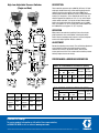
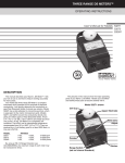
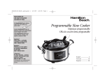
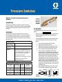
Pressure Switches Moisture-resistant single control pressure switches Moisture Resistant, Adjustable Pressure Switches DESCRIPTION Three factory set models are available for hydraulic pressures from 10 to 4700 psi. All are single pole double throw type (NEMA 4). Each comes complete with a sealed 3-wire cable that is five feet long. ADJUSTMENT OPERATION The adjustment procedure for the high-pressure switch is as follows: WARNING When pressure exceeds the set point, the internal contacts transfer (N.O. closes and N.C. opens). This can be used to send an alarm signal to alert either a high, or low pressure condition. When the abnormal condition is corrected, the contacts return to their normal state. SPECIFICATIONS • Disconnect and lock out all power from the assembly before attempting adjustment. Serious injury may result from electrical shock. • To avoid possible system damage, change the blow out disc or relief valve setting to match the new pressure switch setting. a. Turn off electrical power to the lube system. Ambient Temperature Range 0º to 160ºF (-17º to 71ºC) Max Media Temperature 200ºF (93ºC) c. With power disconnected, slide adjustment “cover” toward cable while twisting it to overcome friction. Electrical Rating & Approvals Rated to 5A resistive and 5A inductive (75% power factor), at 125 VAC & 250 VAC, 1/4 HP; 5A resistive and 3A inductive at 30 VDC; 0.5A resistive & 0.25A inductive at 125 VDC; 5mA at 6 VDC, 2mA at 12 VDC & 1mA at 24 VDC d. Connect continuity tester (VOM or light) to leads. b. Connect switch to pressure source. CE Compliance to pressure equipment, Directive (Ped/97/23/EC) Ordering Information Max. Hydraulic Pressure Adjustment Range, Rising Factory Setting Part No. (Old Part No.) 2000 (138) 50 to 2000 (3 to 138) 50 (3) 557830 (542-210-200) 4700 (324) 400 to 4700 (28 to 324) 750 (52) 557828 (542-210-107) 4700 (324) 400 to 4700 (28 to 324) 1150 (79) 557829 (542-210-120) f. After completing adjustments, slide “cover” closed over adjustment compartment. Recheck set point. 1/2" FEMALE CONDUIT CONNECTOR FACTORY SEALED 3 WIRE CABLE 16 AWG 5 FT. LG. CAUTION RED N.O. LABEL BLACK N.C. WHITE COM. 4.25 (108) 542-210-120 CE Compliance with low voltage directive (LDV) PRESSURE SWITCH UL Recognized, CSA Certified e. Insert screwdriver into adjustment slot and turn clockwise to increase setting or counter-clockwise to decrease setting. For setting on rise, apply desired pressure and turn adjustment (clockwise facing cable end of pressure switch) until switch clicks and/or tester confirms contact transfer (Circuit across N.O. and COM. terminals closes). For setting on fall, apply pressure equal to normal system operating pressure. Reduce source pressure to set point value. Turn adjustment counterclockwise until switch clicks and/ or tester confirms contact transfer (circuit across N.C. and COM. closes). ADJUSTMENT COVER 1.06 (27) HEX 1/4 NPT High-Low, Adjustable Pressure Switches (Single and Dual) DESCRIPTION Three models for pressures up to 3,000 PSI (207 bars). UL listed single-pole, double-throw snap action switching elements with automatic reset by micro-switch snap-action. NEMA Type 3 weather-proof enclosures. Maximum electrical rating (continuous inductive) is 10 amperes / 125 or 250 volts AC or 0.5 amp / 3O volts DC. Approximate weights are 2.5 lb. (1.1 kg.) for the singlecentral models and 3.0 lb. (1.4 kg.) for the dual-control models. Switch wire leads for the single-control models are 3 #18 AWG wires, each approx. 18” (45.7 cm) long; dual-control models have 6 #18 AWG wires each approx. 18” (45.7 cm) long. OPERATION When pressure exceeds the trip setting, it forces the actuator piston against the micro-switch button, activating the switch. Switch remains closed/open until pressure is relieved and piston returns to its original position. Reset is automatic. ADJUSTMENT Remove the adjusting screw cover(s). Turn self-locking adjustment screw clockwise to reduce the pressure point or counterclockwise to increase it. (On the dual switch, there are two screws–one for each line. Each screw must be set to the pressure desired.) Replace and secure cover(s). PERFORMANCE & ORDERING INFORMATION Single-Setting Models Ratings-PSI (Bars) Proof Pressure Adjustable Range Decreasing Min. Max. Increasing Min. Max. Actuation Valve Part No. Differential * (Old Part No) 7000 (483) 125 (9) 1400 (97) 135 (9) 1500 (103) 10 to 60 (0.7 to 4) Disc. (507-509-000) 7000 (483) 250 (17) 2775 (191) 280 (19) 3000 (207) 30 to 225 (2 to 16) Disc. (507-507-000) Dual-Control Models Ratings-pSi (Bars) Terminal Switch Terminal Switch 1 Switch 2 Common Purple Common Purple Brown Norm. Closed Blue Norm. Closed Blue Orange Norm. Open Red Norm. Open Red Yellow Proof Pressure 3000 (207) Adjustable Range Decreasing Min. Max. 35 (2) 375 (26) Increasing Min. Max. 40 (3) Actuation Valve To Order, Use Differential * Part No. 400 (28) 5 to 25 (0.3 to 2) All written and visual data contained in this document are based on the latest product information available at the time of publication. Graco reserves the right to make changes at any time without notice. Contact us today! To receive product information or talk with a Graco representative, call 800-533-9655 or visit us online at www.graco.com. ©2006-2009 Graco Inc. Form No. L15521 Rev. B 3/09 Printed in U.S.A. All other brand names or marks are used for identification purposes and are trademarks of their respective owners. All written and visual data contained in this document are based on the latest product information available at the time of publication. Graco reserves the right to make changes at any time without notice. 558947 (540-367-000)