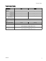
1
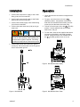
Instructions-Parts
Mix Manifold Kit
3A2801D
For at-the-gun mixing of 2 component materials when used with a ProMix™ PD2K Proportioner.
For professional use only.
Important Safety Instructions
Read all warnings and instructions in this manual and in your PD2K
proportioner manual.
Save these instructions.
See page 2 for model part numbers,
maximum fluid working pressure, and
approvals.
PROVEN QUALITY. LEADING TECHNOLOGY.
EN
Models
2
Part No.
Series
Description
Maximum Fluid Working Pressure
24R991
A
Low Pressure Mix Manifold
300 psi (2.1 MPa, 21 bar)
24R992
A
High Pressure Mix Manifold
1500 psi (10.5 MPa, 105 bar)
24T273
A
High Pressure Mix Manifold, for
acid-catalyzed materials
1500 psi (10.5 MPa, 105 bar)
3A2801D
Warnings
Warnings
The following warnings are for the setup, use, grounding, maintenance and repair of this equipment. The
exclamation point symbol alerts you to a general warning and the hazard symbol refers to procedure-specific
risks. When these symbols appear in the body of this manual or on warning labels, refer back to these
Warnings. Product-specific hazard symbols and warnings not covered in this section may appear throughout
the body of this manual where applicable.
WARNING
FIRE AND EXPLOSION HAZARD
Flammable fumes, such as solvent and paint fumes, in work area can ignite or explode. To help
prevent fire and explosion:
• Use equipment only in well ventilated area.
• Eliminate all ignition sources; such as pilot lights, cigarettes, portable electric lamps, and
plastic drop cloths (potential static arc).
• Keep work area free of debris, including solvent, rags and gasoline.
• Do not plug or unplug power cords, or turn power or light switches on or off when flammable
fumes are present.
• Ground all equipment in the work area. See Grounding instructions.
• Use only grounded hoses.
• Hold gun firmly to side of grounded pail when triggering into pail. Do not use pail liners unless
they are antistatic or conductive.
• Stop operation immediately if static sparking occurs or you feel a shock, Do not use
equipment until you identify and correct the problem.
• Keep a working fire extinguisher in the work area.
SKIN INJECTION HAZARD
High-pressure fluid from gun, hose leaks, or ruptured components will pierce skin. This may
look like just a cut, but it is a serious injury that can result in amputation. Get immediate surgical
treatment.
Do not spray without tip guard and trigger guard installed.
Engage trigger lock when not spraying.
Do not point gun at anyone or at any part of the body.
Do not put your hand over the spray tip.
Do not stop or deflect leaks with your hand, body, glove, or rag.
Follow the Pressure Relief Procedure when you stop spraying/dispensing and before
cleaning, checking, or servicing equipment.
• Tighten all fluid connections before operating the equipment.
• Check hoses and couplings daily. Replace worn or damaged parts immediately.
•
•
•
•
•
•
3A2801D
3
Warnings
WARNING
TOXIC FLUID OR FUMES
Toxic fluids or fumes can cause serious injury or death if splashed in the eyes or on skin,
inhaled, or swallowed.
• Read MSDSs to know the specific hazards of the fluids you are using.
• Store hazardous fluid in approved containers, and dispose of it according to applicable
guidelines.
• Always wear chemically impermeable gloves when spraying, dispensing, or cleaning
equipment.
PERSONAL PROTECTIVE EQUIPMENT
Wear appropriate protective equipment when in the work area to help prevent serious injury,
including eye injury, hearing loss, inhalation of toxic fumes, and burns. This protective
equipment includes but is not limited to:
• Protective eyewear, and hearing protection.
• Respirators, protective clothing, and gloves as recommended by the fluid and solvent
manufacturer.
EQUIPMENT MISUSE HAZARD
Misuse can cause death or serious injury.
• Do not operate the unit when fatigued or under the influence of drugs or alcohol.
• Do not exceed the maximum working pressure or temperature rating of the lowest rated
system component. See Technical Data in all equipment manuals.
• Use fluids and solvents that are compatible with equipment wetted parts. See Technical Data
in all equipment manuals. Read fluid and solvent manufacturer’s warnings. For complete
information about your material, request MSDS from distributor or retailer.
• Do not leave the work area while equipment is energized or under pressure.
• Turn off all equipment and follow the Pressure Relief Procedure when equipment is not in use.
• Check equipment daily. Repair or replace worn or damaged parts immediately with genuine
manufacturer’s replacement parts only.
• Do not alter or modify equipment. Alterations or modifications may void agency approvals
and create safety hazards.
• Make sure all equipment is rated and approved for the environment in which you are using it.
• Use equipment only for its intended purpose. Call your distributor for information.
• Route hoses and cables away from traffic areas, sharp edges, moving parts, and hot surfaces.
• Do not kink or over bend hoses or use hoses to pull equipment.
• Keep children and animals away from work area.
• Comply with all applicable safety regulations.
4
3A2801D
Installation
Installation
Operation
1. Connect the component A supply to the A side
fitting (19a) of the mix manifold.
1. Check that all hose connections are tight before
each use.
2. Connect the component B supply to the B side
fitting (19b) of the mix manifold.
2. To spray, move the lever (16) to the
(SPRAY) position. Components A and B will
enter the mix manifold and be mixed by the mix
nozzle (10) and the static mixer tube (106).
3. Connect the solvent supply to the solvent fitting
(20) of the mix manifold.
4. Connect the static mixer hose (106) to the gun
whip hose.
This equipment must be grounded to reduce
the risk of static sparking. Static sparking can
cause fumes to ignite or explode. Grounding
provides an escape wire for the electric current.
3. To flush, move the lever (16) to the
(FLUSH)
position. Solvent will flush the mix manifold,
static mixer, and gun.
4. To shut down, flush the mix manifold and relieve
pressure as described in the PD2K operation
manual. Always leave the mix manifold lever in
the
(FLUSH) position when not in use.
5. Connect the ground wire (105) to the ground
screw (23). Connect the other end of the ground
wire to a true earth ground.
Figure 2 Mix Manifold Set to Spray
Figure 1 Mix Manifold
3A2801D
Figure 3 Mix Manifold Set to Flush
5
Repair
Repair
Disassembly
1. Flush the mix manifold before servicing. See the
PD2K operation manual.
2. Relieve the pressure as described in the PD2K
operation manual. Disconnect the hoses, taking
note of which port (A or B) they are connected to.
3. Unscrew a plug (15) from the manifold body (1).
Remove and discard the seal (22) each time
a plug is removed. Inspect the seat (12) and
o-rings (13, 14). Replace if damaged.
4. Repeat for the other two plugs (15).
5. Unscrew the outlet fitting (11). Remove the o-ring
(9), bearing (8), mix nozzle (10), and stem ball
(6).
NOTE: When removing the A and B check valves
(19), note which is from the A side and which is
from the B side.
6. Unscrew the check valves (19, 20).
7. Unscrew the packing nut (5). Remove the valve
stem (4), backup washers (3), and o-ring (2).
8. Unscrew the nut (17). Remove the lever (16).
Figure 4 Mix Manifold Repair
6
3A2801D
Repair
Reassembly
NOTE: Lubricate all o-rings when reassembling.
Plug Seals Repair Kit 420011 is available. Parts
included in the kit are marked with an asterisk, for
example (12*). Order the kit separately.
Lever Seals Repair Kit 420012 is available. Parts
included in the kit are marked with a symbol, for
example (2◆). Order the kit separately.
Outlet Seals Repair Kit 420013 is available. Parts
included in the kit are marked with a symbol, for
example (8†). Order the kit separately.
bottoms on the shoulder. Loosely screw the
outlet fitting (11) into the body (1).
5. Apply thread adhesive to the check valves
(19, 20). Be sure to install the A and B check
valves (19) in the correct ports, as noted under
Disassembly.
6. Check that the lever (16) is in the SPRAY
position. This positions the ball stem (6) so the
smooth rounded surface is facing the solvent
port. Proper positioning is important to ensure
that the seal (22) conforms properly against the
ball.
Ball Repair Kit 24T752 is available. Parts included in
the kit are marked with a symbol, for example (6‡).
Order the kit separately.
7. Apply a small amount of fluid compatible grease
to the seat (12) and seal (22). Install them in the
solvent plug port, with the beveled side of the
seat (12) facing in, toward the ball (6).
1. Install the backup washers (3◆) and o-ring (2◆)
on the valve stem (4). Insert the stem into the
body (1).
8. Install the o-rings (13*, 14*) on the solvent plug
(15) and screw the plug into the solvent port
securely.
2. Screw the packing nut (5) into the body (1) so it
bottoms on the shoulder. Install the lever (16)
and nut (17) so the notch (N) in the lever faces
the B side, as shown.
9. Move the lever (16) to the FLUSH position. This
positions the ball stem (6) so the smooth rounded
surface is facing the A and B ports. Repeat steps
7 and 8 for the A and B plugs.
Figure 6 Detail of Seal and Seat Assembly
Figure 5 Lever Orientation
3. Move the lever to the SPRAY position. Install the
stem ball (6) in the manifold body (1) so the small
hole on one side of the stem is facing the side
of the body marked SPRAY (A). The ball must
engage with the valve stem (4).
10. When all three plugs (15) are installed, tighten
the outlet fitting (11).
11. Reconnect the hoses, A to A and B to B.
Reconnect the solvent hose.
12. Return the mix manifold to service.
4. Install the bearing (8†) and o-ring (9†). Insert
the mix nozzle (10) into the stem ball (6) so it
3A2801D
7
Parts
Parts
Mix Manifold Kit Parts
Part No. 24R991 Low Pressure Mix Manifold Kit
Part No. 24R992 High Pressure Mix Manifold Kit
Part No. 24T273 High Pressure Mix Manifold Kit, for acid catalyzed materials
Ref.
No.
Part No. Description
Qty
101
16W557 BRACKET, belt
1
102
16W558 BRACKET, gun/belt
1
103
16W559 RETAINER, bracket
1
104
16W560 NUT, retaining
1
105
16W562 WIRE, ground; 25 ft (7.6 m)
1
106
16W564 HOSE, static mixer; low pressure;
for 24R991; 3/8 npsm (fbe); 9.25
in. (235 mm) long
1
16W563 HOSE, static mixer; high pressure; 1
for 24R992; 3/8 npsm x 1/4 npsm
(fbe); 8.0 in. (203 mm) long
24V437
107
8
HOSE, PTFE, static mixer,
low pressure; for 24R991, 3/8
npsm(fbe), 11.7 in (297 mm) long;
Includes:
1
597350
TUBE, PTFE, 8 in (203 mm)
1
510198
ELEMENT, mixer
3
513832
FITTING, straight,
3/8 T x 3/8 npt, SST
2
207152
FITTING, swivel, 3/8 npt x 3/8 2
npsm, SST
16W556 MANIFOLD, mix; for 24R991
1
17A439
MANIFOLD, mix, for 24R992
1
16W616 MANIFOLD, mix; for 24T273
1
108
16W561 HANDLE, mix manifold
1
109
101550
SCREW, cap, socket head; 1/4–20 1
x 0.5 in. (13 mm)
3A2801D
Parts
Mix Manifold Parts
Part No. 16W556 Mix Manifold (used on 24R991 Kit)
Part No. 17A439 Mix Manifold (used on 24R992 Kit)
Part No. 16W616 Mix Manifold (used on 24T273 Kit for acid-catalyzed materials)
Ref.
No.
Part No.
Description
Qty
11
16W554
FITTING, outlet; 3/8 npsm(m)
1
12*‡
———
SEAT, ball; PEEK
3
13*‡
112319
O-RING; chemically resistant
3
14*‡
121399
O-RING; chemically resistant
6
15
16W551
PLUG; for 16W556
3
24T874
PLUG; for 16W616
3
16
24T838
LEVER
1
17
102310
NUT, hex; 10–32
1
18
———
HANDLE, lever
1
19
VALVE, check; 1/4 npsm
20
See
chart
VALVE, check; 3/8 npsm
See
chart
22*‡
———
SEAL, ball; PPS
3
23
112506
SCREW, ground; 4–40 x 0.25
in. (6 mm)
1
* These parts are included in Plug Seals Repair Kit
420011, which must be ordered separately.
◆ These parts are included in Lever Seals Repair Kit
420012, which must be ordered separately.
† These parts are included in Outlet Seals Repair Kit
420013, which must be ordered separately.
‡ These parts are included in Ball Repair Kit 24T752,
which must be ordered separately.
Ref.
No.
Part No.
Description
Qty
1
———
BODY, manifold
1
2◆
———
O-RING; PTFE
1
3◆
———
WASHER, backup; acetal
2
4
178745
STEM, valve, ball
1
5
165964
NUT, packing
1
Mix
Manifold
16W461,
Ref. 19
16W462,
Ref. 19
16W463,
Ref. 20
6‡
———
BALL, stem
1
16W556
0
2
1
8†‡
———
BEARING, guide; acetal
1
17A439
0
3
0
9†‡
111457
O-RING; PTFE
1
16W616
0
———
NOZZLE, mix
1
1 (installed
in “B” side)
2
10‡
3A2801D
Parts labeled — — — are not available separately.
Quantity of Each Check Valve
9
Accessories
Accessories
Part No.
Description
24N641
1/8 in. (3 mm) ID Fluid Whip Hose; nylon; 6 ft (1.8 m); for high and low pressure applications.
3200 psi (22 MPa, 220 bar) Maximum Fluid Working Pressure.
24N305
1/4 in. (6 mm) ID Fluid Whip Hose; nylon; 6 ft (1.8 m); for low pressure applications only. 225
psi (1.6 MPa, 16 bar) Maximum Fluid Working Pressure.
24N348
1/4 in. (6 mm) ID Fluid Whip Hose; ptfe; 6 ft (1.8 m); for high pressure applications only. 3000
psi (20.7 MPa, 207 bar) Maximum Fluid Working Pressure.
24T753
Acid Catalyst Conversion Kit. To convert a 16W556 standard mix manifold to a 16W616 mix
manifold for use with acid-catalyzed materials.
24T873
Fluid Outlet Quick Disconnect Kit. Replaces the manifold’s fluid outlet fitting to allow
quick-disconnect of the static mixer hose.
24U059
5/16 in. (8 mm) ID Grounded Air Whip Hose, for use with electrostatic guns; 1/4 npsm(f) x
1/4 npsm (f) left–hand thread; 6 ft (1.8 m). 100 psi (0.7 MPa, 7 bar) Maximum Air Working
Pressure.
16F537
5/16 in. (8 mm) ID Air Whip Hose, for use with conventional air spray guns; 1/4 npsm(f); 6 ft
(1.8 m). 200 psi (1.4 MPa, 14 bar) Maximum Air Working Pressure.
24S004
Air Line Quick Disconnect, for use with electrostatic guns.
10
3A2801D
Technical Data
Technical Data
U.S.
Metric
24R991 Low Pressure
Mix Manifold
300 psi
2.1 MPa, 21 bar
24R992 High Pressure
Mix Manifold
1500 psi
10.5 MPa, 105 bar
24T273 High Pressure
Mix Manifold, for
acid-catalyzed materials
1500 psi
10.5 MPa, 105 bar
Mix Manifold
Maximum fluid working
pressure:
Mixing ratio range:
0.1:1 — 50:1, ±1%
Fluid outlet size (static
mixer):
Weight (approximate):
3/8 npt(f)
1.25 lb
0.57 kg
Wetted parts:
16W556 Mix Manifold
302, 303, 316, and 17–4PH SST,
perfluoroelastomer; PEEK, PTFE, CV-75
16W616 Mix Manifold, for
acid-catalyzed materials
3A2801D
302, 316, and 17–4PH SST,
perfluoroelastomer; PEEK, PTFE, CV-75
11
Graco Standard Warranty
Graco warrants all equipment referenced in this document which is manufactured by Graco and bearing its
name to be free from defects in material and workmanship on the date of sale to the original purchaser for use.
With the exception of any special, extended, or limited warranty published by Graco, Graco will, for a period of
twelve months from the date of sale, repair or replace any part of the equipment determined by Graco to be
defective. This warranty applies only when the equipment is installed, operated and maintained in accordance
with Graco’s written recommendations.
This warranty does not cover, and Graco shall not be liable for general wear and tear, or any malfunction,
damage or wear caused by faulty installation, misapplication, abrasion, corrosion, inadequate or improper
maintenance, negligence, accident, tampering, or substitution of non-Graco component parts. Nor shall Graco
be liable for malfunction, damage or wear caused by the incompatibility of Graco equipment with structures,
accessories, equipment or materials not supplied by Graco, or the improper design, manufacture, installation,
operation or maintenance of structures, accessories, equipment or materials not supplied by Graco.
This warranty is conditioned upon the prepaid return of the equipment claimed to be defective to an authorized
Graco distributor for verification of the claimed defect. If the claimed defect is verified, Graco will repair or replace
free of charge any defective parts. The equipment will be returned to the original purchaser transportation
prepaid. If inspection of the equipment does not disclose any defect in material or workmanship, repairs will be
made at a reasonable charge, which charges may include the costs of parts, labor, and transportation.
THIS WARRANTY IS EXCLUSIVE, AND IS IN LIEU OF ANY OTHER WARRANTIES, EXPRESS OR IMPLIED,
INCLUDING BUT NOT LIMITED TO WARRANTY OF MERCHANTABILITY OR WARRANTY OF FITNESS
FOR A PARTICULAR PURPOSE.
Graco’s sole obligation and buyer’s sole remedy for any breach of warranty shall be as set forth above. The
buyer agrees that no other remedy (including, but not limited to, incidental or consequential damages for lost
profits, lost sales, injury to person or property, or any other incidental or consequential loss) shall be available.
Any action for breach of warranty must be brought within two (2) years of the date of sale.
GRACO MAKES NO WARRANTY, AND DISCLAIMS ALL IMPLIED WARRANTIES OF MERCHANTABILITY
AND FITNESS FOR A PARTICULAR PURPOSE, IN CONNECTION WITH ACCESSORIES, EQUIPMENT,
MATERIALS OR COMPONENTS SOLD BUT NOT MANUFACTURED BY GRACO. These items sold, but not
manufactured by Graco (such as electric motors, switches, hose, etc.), are subject to the warranty, if any, of
their manufacturer. Graco will provide purchaser with reasonable assistance in making any claim for breach of
these warranties.
In no event will Graco be liable for indirect, incidental, special or consequential damages resulting from Graco
supplying equipment hereunder, or the furnishing, performance, or use of any products or other goods sold
hereto, whether due to a breach of contract, breach of warranty, the negligence of Graco, or otherwise.
FOR GRACO CANADA CUSTOMERS
The Parties acknowledge that they have required that the present document, as well as all documents, notices
and legal proceedings entered into, given or instituted pursuant hereto or relating directly or indirectly hereto, be
drawn up in English. Les parties reconnaissent avoir convenu que la rédaction du présente document sera en
Anglais, ainsi que tous documents, avis et procédures judiciaires exécutés, donnés ou intentés, à la suite de ou
en rapport, directement ou indirectement, avec les procédures concernées.
Graco Information
For the latest information about Graco products, visit www.graco.com.
To place an order, contact your Graco Distributor or call to identify the nearest distributor.
Phone: 612-623-6921 or Toll Free: 1-800-328-0211 Fax: 612-378-3505
All written and visual data contained in this document reflects the latest product information available at the time of publication.
Graco reserves the right to make changes at any time without notice.
For patent information, see www.graco.com/patents.
Original Instructions. This manual contains English. MM 3A2801
Graco Headquarters: Minneapolis
International Offices: Belgium, China, Japan, Korea
GRACO INC. AND SUBSIDIARIES • P.O. BOX 1441 • MINNEAPOLIS MN 55440-1441 • USA
Copyright 2013, Graco Inc. All Graco manufacturing locations are registered to ISO 9001.
www.graco.com
Revision D, July 2014