1
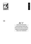
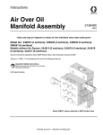
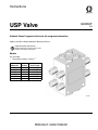
Instructions
USP Valve
3A0860F
EN
Uniblock Series Progressive Valve for oil and grease lubrication.
5076 psi (35 MPa, 350 bar) Maximum Working Pressure
Important Safety Instructions
Read all warnings and instructions in this
manual. Save these instructions.
Models
For all models:
• Discharge per outlet = 0.012 in 3
Model No.
24E406
24E407
24E408
24E409
24E410
24E411
No. of
Outlets
6
8
10
12
14
16
Inlet Thread
1/8 NPT
1/8 NPT
1/8 NPT
1/8 NPT
1/8 NPT
1/8 NPT
ti13743
Warnings
Warnings
The following warnings are for the setup, use, grounding, maintenance, and repair of this equipment. The exclamation point symbol alerts you to a general warning and the hazard symbols refer to procedure-specific risks. When
these symbols appear in the body of this manual, refer back to these Warnings. Product-specific hazard symbols and
warnings not covered in this section may appear throughout the body of this manual where applicable.
WARNING
SKIN INJECTION HAZARD
High-pressure fluid from dispensing device, hose leaks, or ruptured components will pierce skin. This
may look like just a cut, but it is a serious injury that can result in amputation. Get immediate surgical
treatment.
• Do not point dispensing device at anyone or at any part of the body.
• Do not put your hand over the fluid outlet.
• Do not stop or deflect leaks with your hand, body, glove, or rag.
• Follow the Pressure Relief Procedure when you stop dispensing and before cleaning, checking, or
servicing equipment.
• Tighten all fluid connections before operating the equipment.
• Check hoses and couplings daily. Replace worn or damaged parts immediately.
EQUIPMENT MISUSE HAZARD
Misuse can cause death or serious injury.
• Do not operate the unit when fatigued or under the influence of drugs or alcohol.
• Do not exceed the maximum working pressure or temperature rating of the lowest rated system
component. See Technical Data in all equipment manuals.
• Use fluids and solvents that are compatible with equipment wetted parts. See Technical Data in all
equipment manuals. Read fluid and solvent manufacturer’s warnings. For complete information
about your material, request MSDS from distributor or retailer.
• Do not leave the work area while equipment is energized or under pressure. Turn off all equipment
and follow the Pressure Relief Procedure when equipment is not in use.
• Check equipment daily. Repair or replace worn or damaged parts immediately with genuine
manufacturer’s replacement parts only.
• Do not alter or modify equipment.
• Use equipment only for its intended purpose. Call your distributor for information.
• Route hoses and cables away from traffic areas, sharp edges, moving parts, and hot surfaces.
• Do not kink or over bend hoses or use hoses to pull equipment.
• Keep children and animals away from work area.
• Comply with all applicable safety regulations.
2
3A0860F
Installation
Installation
The USP Valve should be ready to install in your system. It has been factory-tested and should not require
any additional modification.
As long as lubricant is supplied under pressure, the
valve will continue to operate . Whenever lubricant flow
ceases, the valve pistons stop. When flow resumes, it
will start again at the same point in the discharge cycle.
NOTE: The manufacturers of the machine tool and its
component bearings should be consulted to ensure that
the ISO 18/14 cleanliness level is adequate.
Outlet Adapters
3. Plug outlet adapter (b) with user supplied plug (c) to
double the output volume.
Lubricant from the plugged outlet adapter is redirected
to the next outlet on the USP divider block flowing in a
clockwise order, following direction arrows (A) stamped
on block (see FIG. 1).
For example in FIG. 1: Removing face seals and plugging 2 outlet adapters will triple the amount of lubricant
at the next outlet. This outlet will include the output of
plugged outlets that are now rerouted as well as it’s own
output.
Pressure Relief Procedure
Each block ships with the correct number of outlet
adapters. Install one adapter into each open outlet port.
Outlet adapters have standard threads for interfacing
with tube fittings.
NOTICE
Loosen inlet connection (B) to allow air to bleed from fitting and relieve pressure in block.
Supplied outlet adapters are required for full functionality and testing.
Recommended Tube Fittings
•
Fittings should have a maximum 9/16 in. (14 mm)
hex.
B
USP Divider Port Combination
3x output
b
A
ti13745
FIG. 2
a
Purging Air From System
c
ti13744
FIG. 1
Before machine operation is resumed, following maintenance or repair procedures, manual system air purging
is required.
USP divider block outlets can be combined to increase
the amount of lubricant for a particular outlet.
1. Remove the outlet adapter from block.
2. Remove face seal (a) from outlet adapter (b) (FIG.
1).
3A0860F
3
Installation
Purging Air from Pump to USP Valve Lines
Steps 1- 3, refer to FIG. 3.
1. Install the line from the system pump to the USP
valve. Do not completely tighten the connection at
the valve’s lube inlet.
2. Cycle the system pump until air-free lubricant is
observed flowing from the line at the valve’s lube
inlet.
3. Tighten the fitting at the lube inlet port while lubricant is still flowing.
The system is now ready for operation.
ti13745
FIG. 3
Purging Air After Adding or Replacing a USP Valve Module
ti14065
FIG. 4
Steps 1- 7, refer to FIG. 4.
5. Attach a hand pump filled with clean, filtered lubricant to the inlet port.
1. Install the new USP valve assembly.
2. Connect the tubing or hoses to the appropriate
valve or lubrication point(s)
6. Operate the hand pump until air-free lubricant is
observed flowing from each lube inlet connector
and/or each lubrication point’s connector.
3. Do not completely tighten the connection(s) at the
inlet or at lubrication points.
7. Tighten the inlet fitting or at the lubrication port while
lubricant is still flowing.
4. Disconnect and remove the line from the pump at
the valve inlet.
8. Remove the hand pump and reconnect the system
pump to the valve inlet.
4
3A0860F
Installation
Blockages
Blocks require a higher than normal pumping pressure.
Depending on the application or system design, this
blockage will usually result in a complete loss of lubricant flow into the total system and no bearing will be
receiving lubrication.
The loss of flow due to a blockage is first indicated with
the higher than normal system pressure that is developed by the pump as it attempts to overcome this blockage. Higher pressure is limited, isolated and signaled
through the use of various performance indicators, reset
and relief, incorporated into the system design. Contact
your Graco distributor for available parts.
Separation Blockage
If a hard wax or soap-like material is found in the Valve
Section, grease separation is occurring. This means that
the oil is being squeezed from the grease at normal system operating pressure and the grease thickener is
being deposited in the divider valve. Cleaning the divider
valve will only temporarily solve the problem. Consult
your lubricant supplier for recommendations on alternate lubricants and your local Graco distributor to verify
compatibility with centralized lubricating systems.
Cleaning Valves
NOTICE
• Dirt and foreign material will damage lubricating
equipment. Perform all service and disassembly
under the cleanest possible conditions.
• Hard or sharp metal objects such as punches,
screwdrivers, and picks can scratch and damage
piston bore. When cleaning these surfaces use a
brass rod and hand pressure only.
1. Remove end plugs only and try to move each piston
back and forth without removing the piston from the
valve section.
If all pistons move freely and there is no indication
of a more serious problem:
2. Replace end plugs.
Contamination Blockage
If dirt, foreign material or any other form of contamination is found in a valve, cleaning that valve will only temporarily solve contamination blockage problems. The
source of the contamination must be eliminated for satisfactory service.
The system filtering method must be investigated, filter
elements should be inspected and cleaned if necessary.
The reservoir filling method should be reviewed to eliminate any chance of foreign material entering the reservoir during filling.
3A0860F
5
Parts
Parts
*
FN Part No. Description
2 1
1
1
2
3
24E757
24E857
ti14066
4
5
6
3
5
24E232
125011
557349
VALVE, 4 piston honed, models
24E406, 24E407
VALVE, 6 piston honed, models
24E408, 24E409
VALVE, 8 piston honed, models
24E410, 24E411
PLUG, w/o ring, models 24E406,
24E407
PLUG, w/o ring, models 24E408,
24E409
PLUG, w/o ring, models 24E410,
24E411
KIT, checked outlet adapter, NPSF
• Model 24E406
• Model 24E407
• Model 24E408
• Model 24E409
• Model 24E410
• Model 24E411
ADAPTER, outlet, NPSF
SEAL, face, elastomeric
PLUG, dry seal 1/8 NPTF (not
shown, shipped loose)
Qty
1
1
1
8
12
16
6
8
10
12
14
16
1
1
1
4 2
1 Torque to 15 - 18 ft.-lbs (20.3 - 24.4 N.m)
2 Torque to 8 - 10 ft.-lbs (10.8 - 13.5 N.m)
6
3A0860F
Technical Data
Technical Data
Wetted Parts
Steel, Fluorocarbon
Maximum Pressure
5076 psi (35 MPa, 350 bar)
Maximum Operating Temperature
Fluorocarbon seals 350°F (177°C)
Lubricant
Oil or grease up to NLGI #2
Output Volume
0.012 in3
Inlet Threads
1/8 - 27 NPT
Outlet Adapter Threads
1/8 - 27 NPSF
Maximum Cycle Rate with Prox Switch
200 cpm
Mounting Holes Accomodate Bolt Diameter
0.25 in. (6 mm)
Dimensions
Mounting Pattern
Width
A
A
Length
B
Thickness
USP
Outlets
6
8
10
12
14
16
3A0860F
B
inch
mm
inch
mm
inch
mm
Mounting
Holes A
inch
mm
2.98
2.98
2.98
2.98
2.98
2.98
75.7
75.7
75.7
75.7
75.7
75.7
2.37
2.37
2.48
2.48
2.88
2.88
60.2
60.2
63.0
63.0
73.2
73.2
1.50
1.50
1.75
1.75
2.25
2.25
38.1
38.1
44.5
44.5
57.2
57.2
2.50
2.50
2.50
2.50
2.50
2.50
Length
Width
Thickness
63.5
63.5
63.5
63.5
63.5
63.5
Mounting
Holes B
inch
mm
1.84
1.84
2.08
2.08
2.40
2.40
46.7
46.7
52.8
52.8
60.9
60.9
7
Technical Data
Outlet Pattern Numbering
NOTE:
•
Port combinations do not continue across factory plugged outlets. Factory plugged ports are included on 6, 10
and 14 outlet USP Valve models. On the following diagrams the factory plugged outlets are represented as
blacked ports.
•
Do not remove plugs from the factory plugged outlets.
/HIW6LGH
9 10
16
15
14 13
5LJKW6LGH
11
8
12
7
1 2
6 5
3
4
3RUW
9 10
16
15
14 13
11
8
12
7
1 2
6 5
3
4
3RUW
12
11
7 8
10
9
6 1 2
5
4
3
3RUW
12
11
7 8
10
9
6 1 2
5
4
3
3RUW
8
5
4
1
7
6
3
2
3RUW
8
5
4
1
7
6
3
2
3RUW
ti14067
8
3A0860F
Notes
Notes
3A0860F
9
Graco Standard Warranty
Graco warrants all equipment referenced in this document which is manufactured by Graco and bearing its name to be free from defects in
material and workmanship on the date of sale to the original purchaser for use. With the exception of any special, extended, or limited warranty
published by Graco, Graco will, for a period of twelve months from the date of sale, repair or replace any part of the equipment determined by
Graco to be defective. This warranty applies only when the equipment is installed, operated and maintained in accordance with Graco’s written
recommendations.
This warranty does not cover, and Graco shall not be liable for general wear and tear, or any malfunction, damage or wear caused by faulty
installation, misapplication, abrasion, corrosion, inadequate or improper maintenance, negligence, accident, tampering, or substitution of
non-Graco component parts. Nor shall Graco be liable for malfunction, damage or wear caused by the incompatibility of Graco equipment with
structures, accessories, equipment or materials not supplied by Graco, or the improper design, manufacture, installation, operation or
maintenance of structures, accessories, equipment or materials not supplied by Graco.
This warranty is conditioned upon the prepaid return of the equipment claimed to be defective to an authorized Graco distributor for verification of
the claimed defect. If the claimed defect is verified, Graco will repair or replace free of charge any defective parts. The equipment will be returned
to the original purchaser transportation prepaid. If inspection of the equipment does not disclose any defect in material or workmanship, repairs will
be made at a reasonable charge, which charges may include the costs of parts, labor, and transportation.
THIS WARRANTY IS EXCLUSIVE, AND IS IN LIEU OF ANY OTHER WARRANTIES, EXPRESS OR IMPLIED, INCLUDING BUT NOT LIMITED
TO WARRANTY OF MERCHANTABILITY OR WARRANTY OF FITNESS FOR A PARTICULAR PURPOSE.
Graco’s sole obligation and buyer’s sole remedy for any breach of warranty shall be as set forth above. The buyer agrees that no other remedy
(including, but not limited to, incidental or consequential damages for lost profits, lost sales, injury to person or property, or any other incidental or
consequential loss) shall be available. Any action for breach of warranty must be brought within two (2) years of the date of sale.
GRACO MAKES NO WARRANTY, AND DISCLAIMS ALL IMPLIED WARRANTIES OF MERCHANTABILITY AND FITNESS FOR A
PARTICULAR PURPOSE, IN CONNECTION WITH ACCESSORIES, EQUIPMENT, MATERIALS OR COMPONENTS SOLD BUT NOT
MANUFACTURED BY GRACO. These items sold, but not manufactured by Graco (such as electric motors, switches, hose, etc.), are subject to
the warranty, if any, of their manufacturer. Graco will provide purchaser with reasonable assistance in making any claim for breach of these
warranties.
In no event will Graco be liable for indirect, incidental, special or consequential damages resulting from Graco supplying equipment hereunder, or
the furnishing, performance, or use of any products or other goods sold hereto, whether due to a breach of contract, breach of warranty, the
negligence of Graco, or otherwise.
FOR GRACO CANADA CUSTOMERS
The Parties acknowledge that they have required that the present document, as well as all documents, notices and legal proceedings entered into,
given or instituted pursuant hereto or relating directly or indirectly hereto, be drawn up in English. Les parties reconnaissent avoir convenu que la
rédaction du présente document sera en Anglais, ainsi que tous documents, avis et procédures judiciaires exécutés, donnés ou intentés, à la suite
de ou en rapport, directement ou indirectement, avec les procédures concernées.
Graco Information
TO PLACE AN ORDER, contact your Graco distributor or call to identify the nearest distributor.
Phone: 612-623-6928 or Toll Free: 1-800-533-9655, Fax: 612-378-3590
All written and visual data contained in this document reflects the latest product information available at the time of publication.
Graco reserves the right to make changes at any time without notice.
Original instructions. This manual contains English. MM 3A0860
Graco Headquarters: Minneapolis
International Offices: Belgium, China, Japan, Korea
GRACO INC. P.O. BOX 1441 MINNEAPOLIS, MN 55440-1441
Copyright 2010, Graco Inc. is registered to ISO 9001
www.graco.com
6/2010, revised 1/2012