1
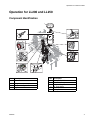
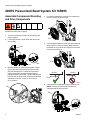
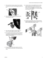
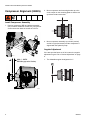
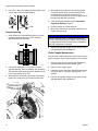
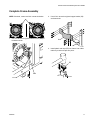
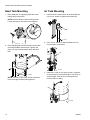
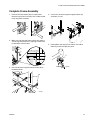
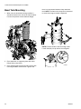
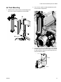
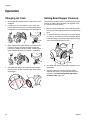
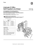
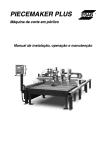
Installation - Operation - Parts Complete Pressurized Bead System for LineLazer IV 200HS and LineLazer IV 250SPS 332230F EN - For professional use only - Models: 16R955 1-Gun LL200HS 16R962 1-Gun LL250 16R960 2-Gun LL200HS 16R961 2-Gun LL250 80 psi (.55 MPa, 5.5 bar) Maximum Working Pressure 9 Important Safety Instructions Read all warnings and instructions in the striper manual. Be familiar with the controls and the proper usage of the equipment. Save these instructions. Related Manual Bead Gun Kit 332226 ti20576b ti24476a Warnings Warnings The following warnings are for the setup, use, grounding, maintenance, and repair of this equipment. The exclamation point symbol alerts you to a general warning and the hazard symbols refer to procedure-specific risks. When these symbols appear in the body of this manual or on warning labels, refer back to these Warnings. Product-specific hazard symbols and warnings not covered in this section may appear throughout the body of this manual where applicable. WARNING FIRE AND EXPLOSION HAZARD Flammable fumes, such as solvent and paint fumes, in work area can ignite or explode. To help prevent fire and explosion: • Use equipment only in well ventilated area. • Do not fill fuel tank while engine is running or hot; shut off engine and let it cool. Fuel is flammable and can ignite or explode if spilled on hot surface. • Keep work area free of debris, including solvent, rags and gasoline. • Ground all equipment in the work area. See Grounding instructions. • Use only grounded hoses. • Hold gun firmly to side of grounded pail when triggering into pail. Do not use pail liners unless they are antistatic or conductive. • Stop operation immediately if static sparking occurs or you feel a shock. Do not use equipment until you identify and correct the problem. • Keep a working fire extinguisher in the work area. EQUIPMENT MISUSE HAZARD Misuse can cause death or serious injury. • Do not operate the unit when fatigued or under the influence of drugs or alcohol. • Do not exceed the maximum working pressure or temperature rating of the lowest rated system component. See Technical Data in all equipment manuals. • Use fluids and solvents that are compatible with equipment wetted parts. See Technical Data in all equipment manuals. Read fluid and solvent manufacturer’s warnings. For complete information about your material, request MSDS from distributor or retailer. • Do not leave the work area while equipment is energized or under pressure. • Turn off all equipment and follow the Pressure Relief Procedure when equipment is not in use. • Check equipment daily. Repair or replace worn or damaged parts immediately with genuine manufacturer’s replacement parts only. • Do not alter or modify equipment. Alterations or modifications may void agency approvals and create safety hazards. • Make sure all equipment is rated and approved for the environment in which you are using it. • Use equipment only for its intended purpose. Call your distributor for information. • Route hoses and cables away from traffic areas, sharp edges, moving parts, and hot surfaces. • Do not kink or over bend hoses or use hoses to pull equipment. • Keep children and animals away from work area. • Comply with all applicable safety regulations. • Do not carry passengers. • Check work area for reduced overhead clearance (e.g. doorways, tree branches, parking ramp ceilings) and avoid contacting them. 2 332230F Warnings WARNING INJECTION HAZARD High-pressure fluid from gun, hose leaks, or ruptured components will pierce skin. This may look like just a cut, but it is a serious injury that can result in amputation. Get immediate surgical treatment. • Do not spray without tip guard and trigger guard installed. • Engage trigger lock when not spraying. • Do not point gun at anyone or at any part of the body. • Do not put your hand over the spray tip. • Do not stop or deflect leaks with your hand, body, glove, or rag. • Follow the Pressure Relief Procedure when you stop spraying and before cleaning, checking, or servicing equipment. • Tighten all fluid connections before operating the equipment. • Check hoses and couplings daily. Replace worn or damaged parts immediately. ENTANGLEMENT HAZARD Rotating parts can cause serious injury. • Keep clear of moving parts. • Do not operate equipment with protective guards or covers removed. • Do not wear loose clothing, jewelry or long hair while operating equipment. • Equipment can start without warning. Before checking, moving, or servicing equipment, follow the Pressure Relief Procedure and disconnect all power sources. MOVING PARTS HAZARD Moving parts can pinch, cut or amputate fingers and other body parts. • Keep clear of moving parts. • Do not operate equipment with protective guards or covers removed. • Pressurized equipment can start without warning. Before checking, moving, or servicing equipment, follow the Pressure Relief Procedure and disconnect all power sources. BURN HAZARD Equipment surfaces and fluid that’s heated can become very hot during operation. To avoid severe burns: • Do not touch hot fluid or equipment. PERSONAL PROTECTIVE EQUIPMENT Wear appropriate protective equipment when in the work area to help prevent serious injury, including eye injury, hearing loss, inhalation of toxic fumes, and burns. This protective equipment includes but is not limited to: • Protective eyewear, and hearing protection. • Respirators, protective clothing, and gloves as recommended by the fluid and solvent manufacturer. CALIFORNIA PROPOSITION 65 The engine exhaust from this product contains a chemical known to the State of California to cause cancer, birth defects or other reproductive harm. This product contains a chemical known to the State of California to cause cancer, birth defects or other reproductive harm. Wash hands after handling. NOTICE Never store glass beads in tank between jobs. Begin the day with moisture-free beads. Moisture will cause glass beads to resist flow or solidify over time. If moisture or condensation is present on tank interior, leave lid open until dry. When operating without the bead system, always leave the moisture drain valve open. 332230F 3 Tools Needed: CE Safety Checklist (To be completed during non-factory installation) Covers and shrouds for moving parts are in place (see guard installation section). Fasteners, belts, covers, grills, and compressor are tight-mounted securely. Read and understand all warnings and instructions in this manual and the striper manual. Tools Needed: • 1/8 in. Allen Wrench (supplied with kit) • Alignment tool 17C504 (supplied with kit) • 5/32 in. Allen Wrench • 1/4 in. Allen Wrench • 3/16 in. Allen Wrench • 7/16 in. Wrench • 3/8 in. Wrench • 1/2 in. Wrench • 5/8 in. Wrench • 9/16 in. Wrench • 11/16 in. Wrench • T-20 Torx Bit • Cutting Blade • Rubber Mallet • Phillips Screwdriver • Straight Edge 4 332230F Operation for LL200 and LL250 Operation for LL200 and LL250 Component Identification 1 9 2 8 3 7 4 6 5 ti24477a Ref. Description 1 2 3 4 332230F Funnel Wing Nut Compressor Bypass Switch Regulator Unloader Ref. Description 5 6 7 8 9 Pressure Relief Valve Bead Tank Gauge Pressure Regulator Valve Air Tank Gauge Safety Relief Valve 5 200HS Pressurized Bead System Kit 16R955 200HS Pressurized Bead System Kit 16R955 Assemble Compressor Mounting and Drive Components 4. Use star bit (supplied) to remove four screws from shroud. Remove original fan grill. NOTE: Glass bead system and paint guns can be mounted on either side of sprayer. 1. Turn off unit. Relieve pressure in paint striper and remove hopper. 2. Locate belt shroud. Loosen knob (AA) and rotate shroud (BB). FF ti20713a 5. Use existing hardware to install new open-centered fan grill (FF). Do not over-tighten. Make sure fan protrudes out, not into the unit. Discard or store old close-centered fan grill. BB ti20715a FF AA 3. With belt guard off, install mounting plate coupler (CC) onto pulley (DD) with two shoulder screws (EE) and serrated nuts. Position slot on back of pulley up and move serrated nut with finger to accept shoulder bolt threads. Tighten shoulder bolt by hand until the teeth on the serrated nut catch the aluminum on the fan. Torque to 16 to 18 ft-lb (21 to 24 N•m). ti20714a Shroud Shroud FF ti20519a 6. Close belt shroud (BB) with new fan grill onto unit. NOTE: You may need to flex shroud around extended shaft on the fan pulley. DD EE BB CC ti20525a ti21196a 6 332230F 200HS Pressurized Bead System Kit 16R955 7. Place key (GG) in keyway opening. Tap into place so that face of key sits recessed slightly from face of hub. 12. Loosely install two screws (MM) and two locknuts (NN) through bottom of frame mount but do not tighten. Remove existing gun arm bracket to gain access to nut (NN). NOTE: See “Compressor Alignment (200HS)” on page 8. GG MM ti20516a 8. Push chain coupler against the shoulder on the mounting plate coupler. NN ti21201a 13. Assemble hopper basket (XX) and base with hardware as shown below. Use 9/16 in. wrench to snug screws. Loosen all six screws 1/4 turn. ti24336a 9. Use 1/8 in. Allen wrench to secure coupler set screw. Torque to 58-62 in-lb (6.6-7.0 N•m). 10. Use hardware (shown below) to mount compressor to compressor bracket (KK). Make certain that the square of the carriage bolt heads are seated in the compressor bracket slots. XX ti21194a KK ti21198c 11. Snug all four nuts down then back the nuts off 1/4 turn. Bracket KK should slide in the slots with some effort. 332230F 7 200HS Pressurized Bead System Kit 16R955 Compressor Alignment (200HS) 2. Move compressor and mounting bracket up to the chain coupler on the mounting plate so that the two sprockets contact each other. Install Compressor Assembly 1. Position compressor (RR) and bracket assembly (SS) on frame. Install four screws (VV), snug all four screws down then back the screws off 1/4 turn. ti24386a 3. Move compressor assembly up or down (vertical) and left or right (horizontal) until the compressor is aligned with the hydraulic pump. Angular Adjustment If the two sprocket faces are in full contact, the angular adjustment is good. Go to “Vertical Adjustment” on page 9. ti24337a 1. The allowable angular misalignment is 1°. 0.80 +/- 0.050 Maintain gap set at factory ti24387a ti24339a 8 332230F 200HS Pressurized Bead System Kit 16R955 2. Adjustment can be made by pushing on the hopper basket vertical supports. ti24341a 2. Use 9/16 in. wrench to tighten compressor bracket screws (VV). VV ti21417a Horizontal Adjustment 1. Tap vertical frame mount with rubber mallet to the left or right. ti24491a 3. After the sprocket faces make full contact, use 9/16 in. wrenches to tighten all six screws. Vertical Adjustment 1. Place a straight edge at the bottom of corresponding teeth of the two sprockets and raise or lower the compressor to adjust until the offset misalignment is minimized (use a straightedge for accurate alignment). Repeat this at both the top and bottom of the sprockets. The allowable offset misalignment is 0.005 to 0.010. LL ti21203a 2. Adjust the horizontal misalignment until the sides of the two hubs are even with each other and the sprocket teeth are in alignment. ti24388a 332230F 9 200HS Pressurized Bead System Kit 16R955 3. Use 9/16 in. wrench to tighten two nuts (NN) to hold vertical frame mount to 200HS frame. 4. After tightening compressor to mounting bracket nuts verify that the 9/32” space between the two sprockets has not changed. Alignment tool (17C504) should slide in and out of the gap between the sprockets with little resistance. 5. If the spacing has changed repeat Compressor Alignment (200HS) procedure. ti21201a NN 6. Properly tighten all screws and nuts. 7. Wrap chain around both sprockets. Install connecting pin and spring clip. Coupler Spacing 1. Slide compressor assembly away from the mounting plate coupler leaving a (C) 9/32” (6.35mm) space between the sprockets. c NOTICE Broken hydraulic pump or compressor shafts may result, if not aligned properly. Always verify compressor alignment whenever a compressor is installed or the belt is tightened or replaced. 8. Install coupler guard using three pan head screws with flatwashers and lockwashers. Chain Coupler Maintenance Periodic chain coupler lubrication is necessary to ensure proper operation of your striper regularly once a month. ti24342a 1. Remove three pan head screws with flatwashers and lockwashers from chain coupler guard. 2. Use spacer alignment tool (17C504) to set the sprocket spacing. Slide tool between the sprockets. The sprocket teeth of both sprockets should sit flush in the inner pockets of the tool. 2. Remove chain coupler guard. 3. With alignment tool holding sprockets in alignment, tighten four compressor to mounting bracket nuts. 4. Install coupler guard using three pan head screws with flatwashers and lockwashers. 3. Lubricate coupler chain with Justice Brothers heavy duty chain lube or equivalent (NLGI grade 1 or 2 grease). ti24389a 10 332230F 200HS Pressurized Bead System Kit 16R955 Complete Frame Assembly NOTE: If desired, rotate recoil 90° counter-clockwise. 2. Use 9/16 in. wrench to tighten hopper basket (XX) and base bolts. ti21500a 1. Use 9/16 wrench to tighten bottom screws (MM) to hardware shown. XX ti21194a 3. Install plastic end caps (ZZ) into frame. Use rubber mallet to pound end caps into place. ZZ MM ti20884a ti21200a 332230F 11 200HS Pressurized Bead System Kit 16R955 Bead Tank Mounting Air Tank Mounting 1. Place bead tank on supporting base with outlet fittings facing compressor. 1. Install air tank to frame mount as shown below and use 9/16 in. wrench to tighten two screws (bb). NOTE: Position handle to best suit filling needs. Loosen bolt (aa) to help swivel, then retighten. bb aa ti20704a 2. Place clamping band around tank and secure with mounting hardware shown below. Tighten until there is no movement between clamp and bead tank. ti21197a 2. Use 11/16 in. wrench to attach braided hose (cc) from air tank to compressor. cc ti21191a ti21193a NOTE: The flats on the clamp are not intended to touch the hopper bracket when tightened. 3. Install 36 in. nylon air line (dd) from top of regulator to swivel fitting on top of bead hopper. Cut air line to desired length. Push air line into fitting until end touches bottom of fitting. dd ti21195a 12 332230F LL250 Pressurized Bead System Kit 16R962 LL250 Pressurized Bead System Kit 16R962 Assemble Compressor Mounting and Drive Components Shroud Shroud F ti20519a NOTE: Glass bead system and paint guns can be mounted on either side of sprayer. 5. Install belt shroud with new fan grill onto unit. NOTE: You may need to flex shroud around extended shaft on the fan pulley. 1. Turn off unit. Relieve pressure in paint striper and remove hopper. B 2. Locate belt shroud. Loosen four screws (A) and remove shroud (B). B A ti20518a 6. Place key (G) in keyway opening. Tap into place so that face of key sits recessed slightly from face of hub. ti20518a 3. With belt guard off, install mounting plate coupler (C) onto pulley (D) with two shoulder screws (E) and serrated nuts. Position slot on back of pulley up and move serrated nut with finger to accept shoulder bolt threads. Tighten shoulder bolt by hand until the teeth on the serrated nut catch the aluminum on the fan. Torque shoulder bolt to 16 to 18 ft-lb (21 to 24 N•m) to secure mounting plate coupler. E C ti20516a 7. Push chain coupler against the shoulder on the mounting plate coupler. D ti20525a 4. Use existing hardware to install new open-centered fan grill (F). Make sure fan protrudes out, not into the unit. Discard or store old close-centered fan grill. 332230F G ti24336a 8. Use 1/8 in. Allen wrench to secure coupler set screw. Torque to 58-62 in-lb (6.6-7.0 N•m). 13 LL250 Pressurized Bead System Kit 16R962 9. Use hardware (shown below) to mount compressor to compressor bracket. Make certain that the square of the carriage bolt heads are seated in the compressor bracket slots. cross member of LL250 frame). NOTE: To ensure flush sitting, scrape frame free of any raised debris on frame surface. Inches Centimeter ti20511a L 13. Cut any existing tie wraps that interfere (they will be replaced later with new tie straps). ti20512a 14. Loosely install two screws (M) and two locknuts (N) through bottom of frame mount. NOTE: See alignment section then use 9/16 in. wrench to fully tighten. ti24480a 10. Snug all four nuts down then back the nuts off 1/4 turn. Bracket KK should slide in the slots with some effort. M 11. Use rubber mallet or wood block to position frame mount (L) flush to LL250 frame (this location will be adjusted to help center the compressor with the drive pulley). N ti20509a 15. Secure hydraulic lines with zip ties. L 12. Place right frame mount (L) onto LL250 frame in location shown below (approximately 1 in. from 14 ti20507a 332230F LL250 Pressurized Bead System Kit 16R962 16. Assemble hopper bracket (X) and base (Y) with hardware provided. Install carriage bolts with the heads facing the paint tanks. Use 9/16 in. wrench to tighten bolts. Loosen all eight nuts 1/4 turn. ti24390a 2.674" Compressor Alignment (LL250) ti24481a 1. Position compressor and bracket assembly on frame. Align compressor coupler sprocket with chain coupler installed on mounting plate coupler. Install three screws, snug all three screws down then back the screws off 1/4 turn. 0.80 +/- 0.050 Maintain gap set at factory ti24339a 332230F 15 LL250 Pressurized Bead System Kit 16R962 2. Move compressor and mounting bracket up to the chain coupler on the mounting plate so that the two sprockets contact each other. 2. Adjustment can be made by pushing on the hopper basket vertical supports. ti24386a 3. Move compressor assembly up or down (vertical) and left or right (horizontal) until the compressor is aligned with the hydraulic pump. Angular Adjustment If the two sprocket faces are in full contact, the angular adjustment is good. Go to “Vertical Adjustment” on page 17. 1. The allowable angular misalignment is 1°. ti24478a 3. After the sprocket faces make full contact, use 9/16 in. wrenches to tighten all eight nuts. ti24340a2 16 332230F LL250 Pressurized Bead System Kit 16R962 Vertical Adjustment 1. Place a straight edge at the bottom of corresponding teeth of the two sprockets and raise or lower the compressor to adjust until the offset misalignment is minimized (use a straightedge for accurate alignment). Repeat this at both the top and bottom of the sprockets. The allowable offset misalignment is 0.005 to 0.010. ti20510a 2. Adjust the horizontal misalignment until the sides of the two hubs are even with each other and the sprocket teeth are in alignment. ti24341a 2. Use 9/16 in. wrench to tighten compressor bracket screws (VV). ti24388a 3. Use 9/16 in. wrench to tighten two nuts (N) to fully clamp vertical frame mount to LL250 frame. N ti20509a Coupler Spacing 1. Slide compressor assembly away from the mounting plate coupler leaving a (C) 9/32” (6.35mm) space between the sprockets. c VV ti24482a Horizontal Adjustment 1. Tap vertical frame mount with rubber mallet to the left or right. ti24342a 332230F 17 LL250 Pressurized Bead System Kit 16R962 2. Use spacer alignment tool (17C504) to set the sprocket spacing. Slide tool between the sprockets. The sprocket teeth of both sprockets should sit flush in the inner pockets of the tool. 5. If the spacing has changed repeat Compressor Alignment (LL250) procedure. 6. Properly tighten all screws and nuts. 7. Wrap chain around both sprockets. Install connecting pin and spring clip. NOTICE Broken hydraulic pump or compressor shafts may result, if not aligned properly. Always verify compressor alignment whenever a compressor is installed or the belt is tightened or replaced. 8. Install coupler guard using three pan head screws with flatwashers and lockwashers. Chain Coupler Maintenance Periodic chain coupler lubrication is necessary to ensure proper operation of your striper regularly once a month. ti24389a 3. With alignment tool holding sprockets in alignment, tighten four compressor to mounting bracket nuts. 4. After tightening compressor to mounting bracket nuts verify that the 9/32” space between the two sprockets has not changed. Alignment tool (17C504) should slide in and out of the gap between the sprockets with little resistance. 18 1. Remove three pan head screws with flatwashers and lockwashers from chain coupler guard. 2. Remove chain coupler guard. 3. Lubricate coupler chain with Justice Brothers heavy duty chain lube or equivalent (NLGI grade 1 or 2 grease). 4. Install coupler guard using three pan head screws with flatwashers and lockwashers. 332230F LL250 Pressurized Bead System Kit 16R962 Complete Frame Assembly 1. Position left frame mount (W) on LL250 frame. Remove any zip ties in the way. Use a rubber mallet to tap into place if needed. 4. Use 9/16 in. wrench to tighten hopper bracket (X) and base (Y) nuts. X Y W ti20501a 2. Make sure left and right frame mounts are aligned. The left leg should mirror the right leg location from LL250 frame cross member. ti24390a 5. Install plastic end caps (Z) into frame. Use rubber mallet to pound end caps into place. Z Inches Centimeter ti20502a 3. Use 9/16 wrench to tighten bottom screws (M) to hardware shown. ti20884a M ti20500a 332230F 19 LL250 Pressurized Bead System Kit 16R962 Bead Tank Mounting 1. When only one bead tank is being installed, it should be placed on the side of the frame furthest from the compressor to best distribute weight. there is no movement between clamp and bead tank. NOTE: The flats on the clamp are not intended to touch when hopper bracket is tightened. ti24485a NOTE: Position handle to best suit filling needs. Loosen bolt (AA) to help swivel, then retighten. ti24483a 2. Place bead tank on supporting base with outlet fittings facing compressor. 3. Place clamping band around tank and secure with mounting hardware shown below. Tighten until 20 AA ti20704a 332230F LL250 Pressurized Bead System Kit 16R962 Air Tank Mounting 2. Use 11/16 in. wrench to attach braided hose (CC) from air tank to compressor. 1. Install air tank to frame mount as shown below and use 9/16 in. wrench to tighten two screws (BB). BB CC BB ti24486a ti24487a 3. Install 36 in. nylon air line (DD) from top of regulator to swivel fitting on top of bead hopper. Cut air hose to desired length. Push air line into fitting until end touches bottom of fitting. DD ti20493a 332230F 21 Operation Operation Charging Air Tank Setting Bead Hopper Pressure 1. Start engine and engage clutch. Compressor is now engaged. The pressure regulator valve (5) controls pressure sent from the air tank to the bead tank. The regulator is set to 0 pressure from the factory. 2. If compressor is not needed for a job, move compressor bypass switch (9) to horizontal ON position. Compressor is now exhausting air into atmosphere. 8 9 ti21074a ti21081a 3. Move compressor bypass switch (9) to vertical OFF position to charge air pressure tank. Air tank will continue to charge to 80 psi (5.5 bar, 55 MPa) then cycle between 60-80 psi (4.1-5.5 bar, 41-55 MPa). 1. Before charging bead tank, confirm that bead tank lid is fully secured and beads have been loaded into tank. 2. To increase pressure, pull knob on pressure regulator valve (5) out and turn counter-clockwise. Watch bead tank gauge (4) pressure and continue turning valve until desired pressure is met. 4 5 ti21073a 8 9 ti21083a ti21082a 4. See bead tank gauge (4) to read air tank pressure. Pressure from air tank is used to open bead valves at bead gun. 4 3. See bead flow chart to find proper settings for your application. 4. Various orifices can be used in gun to obtain different flow rates in conjunction with bead tank pressure. See Determining Bead Application Pressure Table, page 24. ti21079a 22 332230F Operation Bead Timing With Gun 1. Use air flow restrictor valves to help time the opening and closing of the bead guns to best match the start and stop of paint lines. 2. Valve (X) is exhausting air and will control the timing end of the bead application. Valve (Y) is sending air to the gun and will control the timing of the start of the bead application. NOTICE Never store glass beads in tank between jobs. Begin the day with moisture-free beads. Moisture will cause glass beads to resist flow or solidify over time. If moisture or condensation is present on tank interior, leave lid open until dry. When operating without the bead system, always leave the moisture drain valve open. To air tank X Exhaust ti21326a Y To bead gun 3. Turning the valve clockwise will delay gun opening/closing time. Turning the valve counter-clockwise will speed up gun opening/closing time. 332230F 23 Operation Determining Bead Application Pressure The table below lists bead delivery rates for 4 inch (10 cm) lines with standard size highway beads. 2. Identify what the required bead delivery rate is in job specifications. • Wider lines use multiples of 4 in. to determine bead delivery. 3. Under bead gun nozzle size, find nearest value compared to Step 2. • Larger beads reduce flow rates, so a larger nozzle and higher pressure may be required. 4. Match pressure needed to Step 3. Set air regulator to this pressure. • Always verify flow rates with a stopwatch and a scale for weight. † EXAMPLE: To determine application pressure, follow steps 1 - 4 below: 1. Determine speed the machine will travel when applying line. Step 1 mph 2 3 4 5 6 7 8 Step 1 Step 2 Speed mph 2 3 4 5 6 7 8 24 b. At 4 mph and 6 lb/gal with 0.281 nozzle set tank pressure to psi. c. Step 2 Bead Delivery Requirement (4 in.) 6 lb/gal 8 lb/gal lb/min lb/min 3.6 4.7 5.3 7.1 † 7.1 9.5 8.9 11.9 10.7 14.2 12.4 16.6 14.2 19 Speed a. At 4 mph and 6 lb/gal with 0.234 nozzle set tank pressure to 15 psi. Bead Delivery Requirement (10 cm) 720 gram/liter 960 gram/liter lb/min lb/min 3.6 4.7 5.3 7.1 † 7.1 9.5 8.9 11.9 10.7 14.2 12.4 16.6 14.2 19 For 8 in. width, multiply weight/min value (7.1) x 2 and for 12 in. width x 3. Step 3 Step 4 Nozzle Size 0.234 lb/min 4 6 †7 9 11 13 16 0.281 lb/min 5 †7 9 11 14 16 19 Step 3 psi 5 10 15 20 25 30 35 Step 4 Nozzle Size 0.234 lb/min 4 6 †7 9 11 13 16 Pressure Needed 0.281 lb/min 5 †7 9 11 14 16 19 Pressure Needed psi 5 10 15 20 25 30 35 332230F Operation Filling Bead Hopper 1. Move compressor bypass switch (9) to horizontal position to disengage compressor or turn engine off. 4. Place funnel (1) into opening. Pour beads into hopper. Beads should not be filled to a height higher than shown in figure below. Bead level can be viewed through tank wall if light is present. 1 9 ti21074a 2. Release pressure on bead tank to 0 psi (0 bar, 0 MPa). Turn pressure relief valve (8) to vertical position and watch bead tank pressure gauge (3) until pressure reads 0 psi (0 bar, 0 MPa). Do not use safety valve (3) to release pressure from bead tank. 3 ti21076a 5. Secure lid over opening and tighten wing nut until lid is level with hopper. 8 ti21075a ti21081a ti21080a 3. Loosen wing nut (2) until it reaches end of threads. If any remaining pressure is in bead tank, it will be released through seal while wing nut secures lid to hopper. Confirm pressure is at 0 psi (0 bar, 0 MPa) and open lid. 2 ti21077a 332230F 25 Operation 0 to 8 in. Line Setup 2 Tank 1 Gun Setup For wider lines it may be necessary to mount bead gun as shown below. Connect “Y” fitting as shown below to allow two tanks to flow into one gun. ti20977a ti20978b 8 - 12 in. Line Setup ti21085c ti21258a 26 332230F Operation Double Drop Setup Use a “Y” fitting to create a dual bead gun setup for double drop beads. Splice exit hose on bottom of air switch and branch into both guns. ti20564a 332230F 27 Parts - Model 16R955 Parts - Model 16R955 212 207 223 218 221 223 213 209 232 222 235 208 204 210 203 234 219 224 220 226 205 215 211 206 229 222 223 245 230 242 240 214 243 248 228 238 201 251 214a 217 206 227 225 28 220 247 237 ti20720c 250 249 ti20720d 332230F Parts - Model 16R955 Parts List - 16R955 Ref. 201 202 203 204 205 206 207 208 209 210 211 212 213 214 Part 156971 15K299 126804 16U375 16U174 187357 113321 118486 101970 104655 15B565 16T580 16T763 126789 214a 215 216 217 24V932 16T762 101690 16T579 218 219 220 221 222 24V582 111194 111193 115087 121488 332230F Description Qty. FITTING, nipple, short 3 FITTING, tee, street, modification 1 REGULATOR, unloader 1 REGULATOR 1 TANK, pressure 1 ELBOW, street 2 FITTING, elbow, tube 1 FITTING, elbow, push 1 PLUG, pipe, hdls 1 GAUGE, press air 1 VALVE, ball 1 BAND, clamping, bead hopper 1 FRAME, bead hopper, left 1 COMPRESSOR, piston air, 1.7 hp 1 (6 cfm) FAN, compressor 1 FRAME, bead hopper, right 1 TOOL, Allen wrench 1 BRACKET, compressor, 130 and 1 200 TANK, bead 1 SCREW, cap flang hd 2 SCREW, cap flang hd 6 PLUG, tubing 2 SCREW, hex hd, flanged 9 Ref. 223 224 225 226 227 228 229 230 232 234 235 237 238 239 240 241 242 243 245 247 Part 101566 16T593 120757 16T939 110755 126833 116720 16T736 16U273 162453 124762 112958 102040 16T437 120376 16R963 120087 16X197 16U327 16X252 248 249 250 251 117632 867489 116876 100020 Description NUT, lock BRACKET, hopper SCREW, carriage HOSE, coupled WASHER, plain SCREW, shoulder, socket head COUPLER, quick disconnect COUPLER, mounting plate HOSE, pneumatic FITTING, (1/4 npsm x 1/4 npt) GAUGE, pressure, air, bsp NUT, hex, flanged NUT, lock, hex FUNNEL, bead tank KEY, square 0.188 KIT, accessory, bead gun SCREW, set, 1/4 x 1/2 GUARD, coupler, assembly GRILL, fan guard, cap trimmed COUPLING, keyway hub, flex, L type KEY, square, 0.188 x 1.25 SCREW, pan head WASHER, flat WASHER, lock Qty. 11 1 4 1 4 2 1 1 1 1 1 2 4 1 1 1 4 1 1 1 1 3 3 3 29 Parts - Model 16R962 Parts - Model 16R962 15 25 33 13 25 18 50 57 22 56 25 26 62 35 10 25 17 4 12 3 62 34 49 41 45 44 25 26 51 25 5 24 43 42 21 20 26 29 6 14 53 55 54 19 28 30 40 47 52 63 14a 1 6 24 ti24488a 30 27 23 332230F Parts - Model 16R962 Parts List - Model 16R962 Ref. 1 2 3 4 5 6 7 8 9 10 11 12 13 14 Part 156971 15K299 126804 16U375 16U174 187357 113321 118486 101970 104655 15B565 16T580 16T698 126789 14a 15 16 17 18 19 20 21 22 23 24 25 26 27 28 29 24V932 125626 16T437 16T596 16T697 16X197 16U327 16T736 16T594 16T591 111193 101566 111194 120757 102040 116720 332230F Description Qty. FITTING, nipple, short 3 FITTING, tee, street, modification 1 REGULATOR, unloader 1 REGULATOR 1 TANK, pressure 1 ELBOW, street 2 FITTING, elbow, tube 1 FITTING, elbow, push 1 PLUG, pipe, hdls 1 GAUGE, press air 1 VALVE, ball 1 BAND, clamping, bead hopper 1 FRAME, bead hopper, left, LL250 1 COMPRESSOR, piston air, 1.7 1 hp(6 cfm) FAN, compressor 1 SCREW, hex hd, flanged 10 FUNNEL, bead tank 1 BASE, hopper frame, LL250 1 FRAME, bead hopper, right, LL250 1 GUARD, coupler, assembly 1 GRILL, fan guard, cap trimmed 1 COUPLER, mounting plate 1 BRACKET, bead hopper, LL250 1 BRACKET, compressor, LL250 1 SCREW, cap flang hd 4 NUT, lock 15 SCREW, cap flang hd 6 SCREW, hex hd, flanged 4 NUT, lock, hex 4 COUPLER, quick disconnect 1 Ref. 30 32 33 34 35 37 39 40 41 42 43 44 45 47 Part 110755 16U273 115087 162453 124762 101690 16R963 120376 260387 120087 126833 116969 116876 16X252 49 50 51 52 53 54 55 56 57 62 63 16T939 24V582 112958 117632 867489 116876 100020 17A647 111192 124258 16C394 Description WASHER, plain HOSE, pneumatic PLUG, tubing FITTING, (1/4 npsm x 1/4 npt) GAUGE, pressure, air, bsp TOOL, Allen wrench KIT, accessory, bead gun KEY, square 0.188 SCREW, pan hd, x recess SCREW, set, 1/4 x 1/2 SCREW, shoulder, socket head NUT, lock WASHER, flat COUPLING, keyway hub, flex, L type HOSE, coupled, 061120, 1.5 ft TANK, bead NUT, hex, flanged KEY, square, 3/16 x 1.25 SCREW, pan head WASHER, flat WASHER, lock BRACKET, air tank, LL250 SCREW, cap flange head BOLT, carriage LABEL, pinch hazard ISO Qty. 4 1 2 1 1 1 1 2 4 4 2 4 4 1 1 1 2 1 3 3 3 1 2 4 1 Replacement warning labels may be ordered free of charge. 31 Graco Standard Warranty Graco warrants all equipment referenced in this document which is manufactured by Graco and bearing its name to be free from defects in material and workmanship on the date of sale to the original purchaser for use. With the exception of any special, extended, or limited warranty published by Graco, Graco will, for a period of twelve months from the date of sale, repair or replace any part of the equipment determined by Graco to be defective. This warranty applies only when the equipment is installed, operated and maintained in accordance with Graco’s written recommendations. This warranty does not cover, and Graco shall not be liable for general wear and tear, or any malfunction, damage or wear caused by faulty installation, misapplication, abrasion, corrosion, inadequate or improper maintenance, negligence, accident, tampering, or substitution of non-Graco component parts. Nor shall Graco be liable for malfunction, damage or wear caused by the incompatibility of Graco equipment with structures, accessories, equipment or materials not supplied by Graco, or the improper design, manufacture, installation, operation or maintenance of structures, accessories, equipment or materials not supplied by Graco. This warranty is conditioned upon the prepaid return of the equipment claimed to be defective to an authorized Graco distributor for verification of the claimed defect. If the claimed defect is verified, Graco will repair or replace free of charge any defective parts. The equipment will be returned to the original purchaser transportation prepaid. If inspection of the equipment does not disclose any defect in material or workmanship, repairs will be made at a reasonable charge, which charges may include the costs of parts, labor, and transportation. THIS WARRANTY IS EXCLUSIVE, AND IS IN LIEU OF ANY OTHER WARRANTIES, EXPRESS OR IMPLIED, INCLUDING BUT NOT LIMITED TO WARRANTY OF MERCHANTABILITY OR WARRANTY OF FITNESS FOR A PARTICULAR PURPOSE. Graco’s sole obligation and buyer’s sole remedy for any breach of warranty shall be as set forth above. The buyer agrees that no other remedy (including, but not limited to, incidental or consequential damages for lost profits, lost sales, injury to person or property, or any other incidental or consequential loss) shall be available. Any action for breach of warranty must be brought within two (2) years of the date of sale. GRACO MAKES NO WARRANTY, AND DISCLAIMS ALL IMPLIED WARRANTIES OF MERCHANTABILITY AND FITNESS FOR A PARTICULAR PURPOSE, IN CONNECTION WITH ACCESSORIES, EQUIPMENT, MATERIALS OR COMPONENTS SOLD BUT NOT MANUFACTURED BY GRACO. These items sold, but not manufactured by Graco (such as electric motors, switches, hose, etc.), are subject to the warranty, if any, of their manufacturer. Graco will provide purchaser with reasonable assistance in making any claim for breach of these warranties. In no event will Graco be liable for indirect, incidental, special or consequential damages resulting from Graco supplying equipment hereunder, or the furnishing, performance, or use of any products or other goods sold hereto, whether due to a breach of contract, breach of warranty, the negligence of Graco, or otherwise. FOR GRACO CANADA CUSTOMERS The Parties acknowledge that they have required that the present document, as well as all documents, notices and legal proceedings entered into, given or instituted pursuant hereto or relating directly or indirectly hereto, be drawn up in English. Les parties reconnaissent avoir convenu que la rédaction du présente document sera en Anglais, ainsi que tous documents, avis et procédures judiciaires exécutés, donnés ou intentés, à la suite de ou en rapport, directement ou indirectement, avec les procédures concernées. Graco Information For the latest information about Graco products, visit www.graco.com. For patent information, see www.graco.com/patents. TO PLACE AN ORDER, contact your Graco distributor or call 1-800-690-2894 to identify the nearest distributor. All written and visual data contained in this document reflects the latest product information available at the time of publication. Graco reserves the right to make changes at any time without notice. This manual contains English. MM 332230 Graco Headquarters: Minneapolis International Offices: Belgium, China, Japan, Korea GRACO INC. AND SUBSIDIARIES • P.O. BOX 1441 • MINNEAPOLIS MN 55440-1441 • USA Copyright 2013, Graco Inc. All Graco manufacturing locations are registered to ISO 9001. www.graco.com Revision F September 2014