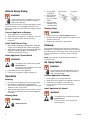
1
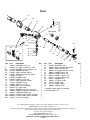
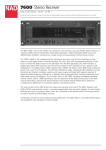
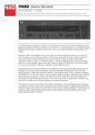
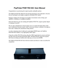
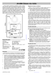
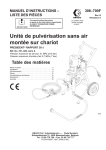
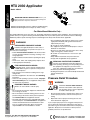
HTX 2030 Applicator
English
Model: 24B327
313537D
IMPORTANT SAFETY INSTRUCTIONS. Refer to your
sprayer instruction manual for Pressure Relief, priming and
spray instructions. Keep these instructions.
ti13583a
Maximum Fluid Working Pressure: 1,000 psi (6.9 MPa, 69 bar)
Maximum Air Working Pressure: 250 psi (1.7 MPa, 17 bar)
-
For Water-Based Materials Only -
The following Warnings are for the setup, use, grounding, maintenance and repair of this equipment. The exclamation point
symbol alerts you to a general warning and hazard symbols refer to procedure-specific risks. Refer back to these Warnings.
Additional, product-specific warnings may be found throughout the body of this manual where applicable.
• Check equipment daily. Repair or replace worn or damaged parts immediately with genuine manufacturer’s
replacement parts only.
• Do not alter or modify equipment.
• Use equipment only for its intended purpose. Call your
distributor for information.
• Route hoses and cables away from traffic areas, sharp
edges, moving parts, and hot surfaces.
• Do not kink or over bend hoses or use hoses to pull
equipment.
• Keep children and animals away from work area.
• Comply with all applicable safety regulations.
WARNINGS
PRESSURIZED EQUIPMENT HAZARD
Fluid from the applicator/dispense valve, leaks, or
ruptured components can splash in the eyes or on
skin and cause serious injury.
• Follow Pressure Relief Procedure in this manual, when
you stop spraying and before cleaning, checking, or servicing equipment.
• Tighten all fluid connections before operating the equipment.
• Check hoses, tubes, and couplings daily. Replace worn
or damaged parts immediately.
PERSONAL PROTECTIVE EQUIPMENT
You must wear appropriate protective equipment
when operating, servicing, or in the operating area of
the equipment to help protect you from serious
injury. This equipment includes but is not limited to:
• Protective eyewear and hearing protection
• Clothing and respirator as recommended by the fluid and
solvent manufacturer
• Gloves
Instructions/Parts
FIRE AND EXPLOSION HAZARD
Flammable fumes, such as solvent and paint fumes,
in work area can ignite or explode. To help prevent
fire and explosion:
• Keep work area free of debris, including solvent, rags
and gasoline.
• Ground all equipment in the work area. See Grounding
instructions.
• If there is static sparking or you feel a shock, stop operation immediately. Do not use equipment until you identify and correct the problem.
Pressure Relief Procedure
WARNING
EQUIPMENT MISUSE HAZARD
Follow this Pressure Relief Procedure
whenever instructed to relieve pressure,
stop spraying, check or service equipment,
or install or clean spray tip.
Misuse can cause death or serious injury.
• Do not operate the unit when fatigued or under the influence of drugs or alcohol.
• Do not exceed the maximum working pressure or temperature rating of the lowest rated system component.
See Technical Data in all equipment manuals.
• Use fluids and solvents that are compatible with equipment wetted parts. See Technical Data in all equipment
manuals. Read fluid and solvent manufacturer’s warnings. For complete information about your material,
request MSDS forms from distributor or retailer.
Graco Inc. P.O. Box 1441 Minneapolis, MN 55440-1441
Copyright 2008, Graco Inc. is registered to I.S. EN ISO 9001
1.
2.
Shut off gasoline engine or unplug electric power cord
and turn sprayer pressure control to lowest pressure
setting.
Open drain valve at sprayer and verify pressure has
been relieved into supply pail.
If you suspect spray tip or hose is clogged or that pressure
has not been fully relieved after following the steps above,
place thick rag over connection between hose and sprayer or
applicator. Slowly loosen connection to relieve pressure
gradually. Clear hose or tip obstruction.
Airless Spray Setup
2.
WARNING
3.
To prevent injury when the applicator is not in use,
always relieve pressure if sprayer is being shut
down or left unattended.
4.
Make sure pressure control is turned off and gasoline engine
is shut off or power cord is unplugged from power source.
Refer to your sprayer instruction manual for priming and spray
instructions.
Attach supply hose to sprayer fluid outlet.
Attach other end of supply hose to applicator swivel (13).
Refer to sprayer instruction manual for priming
instructions.
(4) Vertical
ti11909a
Clearing Clogs
WARNING
Connect Applicator to Sprayer
1.
2.
3.
Loosen guard
(3) Horizontal
retaining nut.
Align guard (32)
horizontally to
spray a horizontal
pattern.
Align guard (32)
ti11908a
vertically to spray
a vertical pattern.
1.
2.
3.
Relieve pressure (see Pressure Relief procedure).
Rotate tip (31) 180°. Open applicator into hopper or onto
ground to remove clog.
Rotate tip (31) 180° back to spray position.
Install Fluid Filter or Plug
1.
2.
When spraying fluids with small aggregates, install filter
support (21) and filter (20, 20a) to reduce tip clogging.
When spraying with large spray tips and fluids with larger
aggregates, install plug (20b) to prevent fluid from
entering air passage in housing (1).
Install Applicator Tip and Guard
WARNING
3.
4.
1.If equipment has recently been operated,
relieve pressure.
2.Using a pencil or similar object, insert seal
(25) into back of guard (32).
Install guard (32) onto end of applicator.
Insert tip (31) in guard (32). Tighten retaining nut.
Operation
Spraying
1.
2.
3.
Be sure the arrow shaped tip (31) faces forward (spray).
Hold applicator perpendicular and approximately
40 in. (1 m) from surface. Move applicator first, then open
applicator to spray a test pattern.
Slowly increase pump pressure until coverage is uniform
and even (see sprayer instruction manual for additional
information).
Aligning Spray
WARNING
Cleanup
Thoroughly flush applicator after each work session before
fluid begins to cure in applicator. Remove check valve (2) and
clean all residue from air passages. Store in a dry location. Do
not leave the applicator or any parts in water or cleaning
solvents.
NOTE: Check valve (15) will be damaged if any object is
inserted into valve.
Air Spray Setup
WARNING
To prevent injury when the applicator is not in use,
always relieve pressure if sprayer is being shut
down or left unattended.
Connect Applicator to Sprayer
1.
2.
3.
4.
Attach supply hose to sprayer fluid outlet.
Attach other end of supply hose to applicator swivel (13).
Install air hose to applicator check valve (15).
Refer to sprayer instruction manual for priming
instructions.
Install Applicator Air Nozzle
WARNING
1.If equipment has recently been operated,
relieve pressure.
2.Install air nozzle (10, 27, 28, 29) and
retaining ring (11).
1.Relieve pressure.
2
313537D
Operation
Spool Valve Repair
Spraying
WARNING
1. Set material flow (see sprayer instruction manual for
additional information).
2. Spray test pattern
3. Turn air knob on and adjust, and/or select another
air nozzle, for desired pattern.
Note: Air continues to flow when handle is in off position
to keep material out of air passages.
Cleanup
Flush applicator after each work session before fluid
begins to cure in applicator. Remove check valve (15)
and clean all residue from air passages. Store in a dry
location. Do not leave the applicator or any parts in
water or cleaning solvents.
NOTE: Check valve (15) will be damaged if any object is
inserted into valve.
Before performing any maintenance on applicator, read
all warnings on front cover of this manual and relieve
pressure.
Spool Valve Removal
1. Remove screw (3d) and handle (8) from spool (3).
2. Remove retaining ring (3c) and bearing (3b).
3. Remove spool (3) from housing (1).
Spool Valve Installation
1. Apply grease (supplied with Kit 24B329) to spool,
o-rings and bearing and inside of housing.
2. Assemble o-rings onto spool.
3. Install spool in housing and bearing. Secure with
retaining ring (3c).
4. Install handle with screw.
All sealing surfaces must be clean to prevent leaks
and damage to equipment.
Technical Data
Maximum fluid working pressure
Maximum air working pressure
Air Requirements
Fluid Inlet Size
Air Inlet Size
Wetted Parts
1000 psi (6.9 MPa, 69 bar)
250 psi (1.7 MPa, 17 bar)
30 scfm (0.84 m3/min) Maximum
1 in.(m) cam and groove (Graco HP)
1/4 npsm(m)
Aluminum, stainless steel, PE, POM, polyurethane, nitrile, nylon, PVC, tungsten
carbide
2.9 lb (1,3 kg)
5.8 in. (14,7 cm)
7.0 in. (17,8 cm)
12.7 in. (32,3 cm)
Weight †
Height
Width
Length †
Sound Data without Air (applicator
only):
Sound Pressure Level
84dB(A)*
Sound Power Level
83dB(A)*
Sound Data with Air (applicator
only):
Sound Pressure Level
118dB(A)*
Sound Power Level
118dB(A)*
* Spraying simulated acoustical texture under typical conditions as specified by the material manufacturer.
† Airless configuration
313537D
3
Parts
19
13
18
12
1
10,27,28,29
11
14
15
4
3a
3
17
33
34
31
3
20
3b
3c
35
36
21
22
8
23
3d
11
25
??
Qty.
1
3
3a*
3b*
3c*
3d*
4
8*
10
11
12
13
14
15
17
18
19
20†
20a†
20b
Part
15W371
24B329
121576
15W376
122205
113045
122206
15W377
248524
15Y137
111027
24B568
15U368
289919
122521
24B328
289874
289922
289923
15X791
Description
Qty.
HOUSING, valve, htx
1
KIT, spool, includes 3a - 3d, 8
PACKING, o-ring, urethane 114
2
WASHER, bearing
1
RING, retaining, internal
1
SCREW, sems, mach, phillips
1
PIN, drive
1
HANDLE, valve
1
NOZZLE, 4 mm, rnd
1
RING, retaining, splined
1
PACKING, o-ring
1
SWIVEL, assy, htx
1
NUT, cap, 1/4-18 npsm
1
KIT, check valve
1
SCREW, machine, 1/4-20 x 2.5
1
HANDLE, applicator (includes 17)
1
COUPLER, female, qd
1
FILTER, screen, texture, 18 mesh
1
FILTER, screen, texture, 30 mesh
1
PLUG, air, passage
1
Qty.
21
22
23
25
27
28
29
31
32
33
34
35
36
Part
277789
15U687
15D727
246453
248525
248526
248527
LTX671
246215
169967
121591
112779
156823
32
ti14501b
Description
SUPPORT, filter
SEAL, adapter, filter, texture
ADAPTER, ghd Rac
KIT, gasket and seat (5 sets)
NOZZLE, 6mm, rnd
NOZZLE, 8mm, rnd
NOZZLE, 10mm, rnd
TIP, spray, Rac X (671)
GUARD, Rac X
FITTING, air QD
KNOB, valve
VALVE, needle
UNION, swivel
* Included in Spool Repair Kit 24B329
† Includes support 21
For complete warranty information contact your local Graco distributor, call Graco customer service:
1-800-690-2894 or visit our website: www.graco.com.
All written and visual data contained in this document reflects the latest product information available at the time of publication.
Graco reserves the right to make changes at any time without notice.
This manual contains English. MM 313537
Graco Headquarters: Minneapolis
International Offices: Belgium, China, Japan, Korea
GRACO INC. P.O. BOX 1441 MINNEAPOLIS, MN 55440-1441
02/2009
Qty.
2
1
1
1
1
1
1
1
1
1
1
1
1