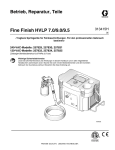
1
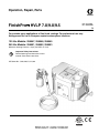
Operation, Repair, Parts
FinishPro™ HVLP 7.0/9.0/9.5
313406L
EN
For portable spray applications of fine finish coatings. For professional use only.
Not approved for use in European explosive atmosphere locations.
120 Vac Models: 256847, 256848, 256849
240 Vac Models: 256851, 256852, 256853
Maximum Working Pressure: 10 psi (0,07 MPa, 0.7 bar)
Important Safety Instructions
Read all warnings and instructions in this
manual. Save these instructions.
US Patent No.: 7,950,598, 7,971,806
ti12834a
Table of Contents
Table of Contents
Warnings . . . . . . . . . . . . . . . . . . . . . . . . . . . . . . . . . 3
Grounding and Electric Requirements . . . . . . . . 5
Component Identification . . . . . . . . . . . . . . . . . . . . 6
Setup . . . . . . . . . . . . . . . . . . . . . . . . . . . . . . . . . . . . . 7
Fluid Preparation . . . . . . . . . . . . . . . . . . . . . . . . . 7
Connect Fluid and Air Supply . . . . . . . . . . . . . . . 7
Pressure Relief Procedure . . . . . . . . . . . . . . . . . 7
Operation Tips . . . . . . . . . . . . . . . . . . . . . . . . . . . 7
Maintenance . . . . . . . . . . . . . . . . . . . . . . . . . . . . . . . 8
Troubleshooting . . . . . . . . . . . . . . . . . . . . . . . . . . . . 9
Repair . . . . . . . . . . . . . . . . . . . . . . . . . . . . . . . . . . . 10
Sprayer Disassembly . . . . . . . . . . . . . . . . . . . . 10
Sprayer Assembly . . . . . . . . . . . . . . . . . . . . . . . 10
2
Turbine Replacement . . . . . . . . . . . . . . . . . . . . . . . 11
Wiring Diagrams . . . . . . . . . . . . . . . . . . . . . . . . . . 12
Technical Data . . . . . . . . . . . . . . . . . . . . . . . . . . . . 13
Parts . . . . . . . . . . . . . . . . . . . . . . . . . . . . . . . . . . . . 14
Parts List . . . . . . . . . . . . . . . . . . . . . . . . . . . . . . . . 15
Parts Drawing . . . . . . . . . . . . . . . . . . . . . . . . . . . . . 16
Parts List . . . . . . . . . . . . . . . . . . . . . . . . . . . . . . . . 17
Graco Standard Warranty . . . . . . . . . . . . . . . . . . . 18
313406L
Warnings
Warnings
The following warnings are for the setup, use, grounding, maintenance and repair of this equipment. The exclamation
point symbol alerts you to a general warning and the hazard symbol refers to procedure-specific risks. Refer back to
these warnings. Additional, product-specific warnings may be found throughout the body of this manual where
applicable.
WARNING
GROUNDING
This product must be grounded. In the event of an electrical short circuit, grounding reduces the risk of
electric shock by providing an escape wire for the electric current. This product is equipped with a cord having a grounding wire with an appropriate grounding plug. The plug must be plugged into an outlet that is
properly installed and grounded in accordance with all local codes and ordinances.
•
•
•
•
•
•
•
•
Improper installation of the grounding plug is able to result in a risk of electric shock.
When repair or replacement of the cord or plug is required, do not connect the grounding wire to either
flat blade terminal.
The wire with insulation having an outer surface that is green with or without yellow stripes is the
grounding wire.
Check with a qualified electrician or serviceman when the grounding instructions are not completely
understood, or when in doubt as to whether the product is properly grounded.
Do not modify the plug provided; if it does not fit the outlet, have the proper outlet installed by a qualified electrician.
This product is for use on a nominal 120V circuit and has a grounding plug similar to the plug illustrated
in the figure below.
Only connect the product to an outlet having the same configuration as the plug.
Do not use an adapter with this product.
Extension Cords:
• Use only a 3-wire extension cord that has a 3-blade grounding plug and a 3-slot receptacle that
accepts the plug on the product.
• Make sure your extension cord is not damaged. If an extension cord is necessary, use 12 AWG
(2.5 mm2) minimum to carry the current that the product draws.
• An undersized cord results in a drop in line voltage and loss of power and overheating.
313406L
3
Warnings
WARNING
FIRE AND EXPLOSION HAZARD
Flammable fumes, such as solvent and paint fumes, in work area can ignite or explode. To help prevent fire and explosion:
•
Do not spray flammable or combustible materials near an open flame or sources of ignition such as cigarettes,
motors, and electrical equipment.
•
Paint or solvent flowing through the equipment is able to result in static electricity. Static electricity creates a risk of
fire or explosion in the presence of paint or solvent fumes. All parts of the spray system, including the pump, hose
assembly, spray gun, and objects in and around the spray area shall be properly grounded to protect against static
discharge and sparks. Use Graco conductive or grounded high-pressure airless paint sprayer hoses.
•
Verify that all containers and collection systems are grounded to prevent static discharge.
•
Connect to a grounded outlet and use grounded extensions cords. Do not use a 3-to-2 adapter.
•
Do not use a paint or a solvent containing halogenated hydrocarbons.
•
Keep spray area well-ventilated. Keep a good supply of fresh air moving through the area. Keep pump assembly in
a well ventilated area. Do not spray pump assembly.
•
Do not smoke in the spray area.
•
Do not operate light switches, engines, or similar spark producing products in the spray area.
•
Keep area clean and free of paint or solvent containers, rags, and other flammable materials.
•
Know the contents of the paints and solvents being sprayed. Read all Material Safety Data Sheets (MSDS) and
container labels provided with the paints and solvents. Follow the paint and solvents manufacturer’s safety instructions.
•
Fire extinguisher equipment shall be present and working.
•
Sprayer generates sparks. When flammable liquid is used in or near the sprayer or for flushing or cleaning, keep
sprayer at least 20 feet (6 m) away from explosive vapors.
ELECTRIC SHOCK HAZARD
Improper grounding, setup, or usage of the system can cause electric shock.
•
Turn off and disconnect power cord before servicing equipment.
•
Use only grounded electrical outlets.
•
Use only 3-wire extension cords.
•
Ensure ground prongs are intact on sprayer and extension cords.
•
Do not expose to rain. Store indoors.
TOXIC FLUID OR FUMES HAZARD
Toxic fluids or fumes can cause serious injury or death if splashed in the eyes or on skin, inhaled, or swallowed.
•
Read MSDS’s to know the specific hazards of the fluids you are using.
•
Store hazardous fluid in approved containers, and dispose of it according to applicable guidelines.
EQUIPMENT MISUSE HAZARD
Misuse can cause death or serious injury.
•
Always wear appropriate gloves, eye protection, and a respirator or mask when painting.
•
Do not operate or spray near children. Keep children away from equipment at all times.
•
Do not overreach or stand on an unstable support. Keep effective footing and balance at all times.
•
Stay alert and watch what you are doing.
•
Do not operate the unit when fatigued or under the influence of drugs or alcohol.
•
Do not kink or over-bend the hose.
•
Do not expose the hose to temperatures or to pressures in excess of those specified by Graco.
•
Do not use the hose as a strength member to pull or lift the equipment.
PRESSURIZED ALUMINUM PARTS HAZARD
Do not use 1,1,1-trichloroethane, methylene chloride, other halogenated hydrocarbon solvents or fluids containing such
solvents in pressurized aluminum equipment. Such use can cause serious chemical reaction and equipment rupture,
and result in death, serious injury, and property damage.
PERSONAL PROTECTIVE EQUIPMENT
You must wear appropriate protective equipment when operating, servicing, or when in the operating area of the equipment to help protect you from serious injury, including eye injury, inhalation of toxic fumes, burns, and hearing loss. This
equipment includes but is not limited to:
•
Protective eyewear and hearing protection
•
Gloves, clothing and respirator as recommended by the fluid and solvent manufacturer
4
313406L
Warnings
WARNING
CALIFORNIA PROPOSITION 65
The engine exhaust from this product contains a chemical known to the State of California to cause
cancer, birth defects or other reproductive harm.
Grounding and Electric Requirements
Use 3-wire, 12 awg, 50 ft (15 m) or shorter, extension
cords with ground prong.
This equipment requires a 120 Vac, 60 Hz, 15A circuit,
with a grounding receptacle.
Do not alter the ground prong or use an adapter.
Sprayer Components Table
Sprayer
Model
Hose
Gun
Fluid Sets
FinishPro 7.0
256847, 256851
30-ft
256855 EDGE
#3
FinishPro 9.0
256848, 256852
30-ft
256855 EDGE
#3, #4
FinishPro 9.5
256849, 256853
30-ft and 4-ft
256855 EDGE
#2, #3, #4
313406L
5
Component Identification
Component Identification
G
S
T
C
R
E
L
M
U
N
A
B
D
H
F
K
J
P
ti12858a
Item
A Sprayer air outlet
Item
Description
HVLP connector for air supply to HVLP spray Gun
K
Resettable circuit
breaker
Provides protection for motor
Quick
connect
Enables quick connection to
spray gun
B
Sprayer power
switch
On/Off switch for sprayer
motor
L
C
Fluid storage
compartment
Provides storage for up to
four fluid sets
M Air valve
D Sprayer handle
Folds flat for minimum storage space
Provides FinishPro 9.0 and
9.5 sprayers ability to shut off
air to spray gun
E
Power
cord storage
Provides storage for power
cord
N Air hose
Hose, 30 ft x 1 in., that connects spray gun and sprayer.
F
Air filters (pre-filter and main)
Provides filtered air for spray
gun and motor
EDGE™
P
Hose wrap
R Storage tray
Provides storage for air hose
when air hose is not in use
Provides extra storage
G Spray gun
Graco
spray gun
™ trigger
with EasyGlide
S
Cleaning cup
holder
Provides storage for cleaning
cup
H Air filter indicator
Lights when air filter needs to
be cleaned or replaced
T
EDGE spray gun
holder
Provides external storage for
spray gun
Provides power for sprayer
(power cord provided with
sprayer)
U Hose, 4-ft
J
6
Description
Connector and
power cord
Allows increased flexibility for
the FinishPro 9.5
313406L
Setup
Setup
Fluid Preparation
Pressure Relief Procedure
•
Strain fluids before you spray. This includes color,
reducers and hardeners.
•
Use a slower drying reducer or thinner to compensate for the faster drying time caused by the warm air
of the turbine. Do not over reduce
•
Sprayer performance varies with the viscosity of the
material sprayed and the length of the hose. To prevent pressure drop, use hose supplied with sprayer.
•
Most material manufacturers provide recommendations for their materials. Follow these recommendations.
Connect Fluid and Air Supply
The spray gun siphon cup is pressurized by the gun
air supply. To reduce the risk of serious injury from
pressurized fluid or accidental spray from gun, always
turn off the air supply to the spray gun before removing the siphon cup.
1. Turn off sprayer.
2. Unplug sprayer.
3. Unlatch cup cover; loosen or remove cup from cover
to relieve pressure.
Spray Gun with Siphon Cup
Operation Tips
1. Connect air hose to sprayer.
Hand tighten.
Sparks can be expected during normal operation of
motor. These sparks can ignite fumes from flammable
liquids, dust particles, and other flammable substances in the spray area.
• Use additional hose if necessary, and ensure the
sprayer is operated in clean, dry, well ventilated
area.
• Never use sprayer inside spray booth.
ti13082a
2. Connect air hose from sprayer to
inlet fitting of gun.
•
Turn sprayer on a few minutes before spraying to
allow warm-up.
•
Ensure sprayer filter is clean before operating. Clean
filter, page 8.
•
To adjust spray gun pattern, see HVLP EDGE Gun
manual 313317.
•
To get proper adhesion, ensure surface is completely
clean.
•
Always spray with the least amount of pressure
required to provide the desired spray pattern and rate
of application. Spraying at pressures higher than necessary wastes paint and can result in an orange peel
finish.
ti12797a
3. Fill cup 3/4 full. Install cover. Latch
the gun cup cover to secure it to
siphon cup. See HVLP EDGE Gun
manual 313317 for operation
instructions.
ti12872a
Connect to Electric Supply
Plug sprayer power cord into grounded outlet. Grounding
and Electric Requirements, page 5.
313406L
7
Maintenance
Maintenance
The sprayer system is lifetime lubricated. The only maintenance required is filter cleaning and replacement.
Filter Operation
The sprayer filter must be clean at all times to provide sufficient air flow to cool the motor and atomize the fluid.
To avoid electric shock, never install a damp filter in the
turbine. Installing a damp filter in sprayer can also
damage turbine.
The sprayer has an air filter indicator light on the front
panel. The indicator light illuminates if the filter is clogged
or has low airflow.
21
ti8049a
20
17
Cleaning Filter
18
ti13061a
1. Turn off and unplug sprayer.
2. Loosen four screws (18), remove filter retainer (17)
and pre-filter (20).
3. Remove main filter (21) and clean using one of the
following methods:
8
•
Tap filter gently on flat surface, dirty side down.
•
Direct, compressed air 100 psi (7 bar, 70 MPa)
(maximum) through filter panel in the opposite
direction of arrows on side of filter from the clean
side to the dirty side.
•
Soak filter for 15 minutes in water and mild detergent. Rinse filter until clean. Air dry.
313406L
Troubleshooting
Troubleshooting
Problem
No fluid delivery
Cause
No material, no remote cup pressurization, hose or pickup tube clogged
Solution
Check cup for material
Check for leaks at the container gasket (1-quart remote cup cover).
Tighten cover if loose.
Check air flow (approximately 1/4
CFM) from male quick-disconnect at
Compact outlet.
Turn pressure regulator clockwise.
Look for pressure on gauge. (If no
pressure on gauge, check air line fittings.)
Check hole in 1-quart remote cup
cover at needle valve for blockage or
dirt. Clean if necessary.
Check for obstructions.
Check if fluid pickup tube is loose.
Tighten.
Blow out and clear material hose.
Clean check valve. See manual
313317
Sprayer not starting
No power
Check outlet for power. Cycle red
rocker switch.
Check that correct IEC (modular)
cord is used and plugged in.
Check circuit breaker (38). Push to
reset.
Poor atomization
Circuit breaker trips
313406L
Dirty filter
Clean filter and replace as necessary.
Extension cord too long
Extension cord must be 3-wire, 12
AWG, 50 ft (15 m) or shorter.
Hose too long
Replace with shorter hose. See
Graco Fine Finish Solutions brochure
300564, for hose part numbers.
Filter clogged
Clean filter and replace as necessary
High ambient temperature
Move sprayer to cooler area.
Excessive current draw
Return to authorized service center.
9
Repair
Repair
Sprayer Disassembly
3. Place sprayer upside down. Remove four screws (77)
from sprayer base plate (2).
77
2
To avoid injury, including electric shock turn off sprayer
and unplug power cord before performing any repair
procedures on the turbine.
1. Remove four thumbscrews (18) and remove filter
retainer (17), prefilter (20) and main filter (16). Parts,
page 14.
ti12973a
4. Pull up sprayer base plate and attached parts.
Thread motor wires that connected to inlet plug
through access in HVLP box.
5. Repair or replace any required parts.
Sprayer Assembly
18
1. Replace duct gaskets (59, 60) and any other damaged or worn parts. Replace circuit breaker (32), if it
has cycled. Remove residual adhesive from previous
gaskets by wiping any sticky surfaces with mineral
spirits solvent (also called white spirit). Let solvent
evaporate thoroughly before installing replacement
gasket.
16
20
17
ti13061a
2. Remove two screws (101) and inlet plug (61) from
HVLP box (1). Remove three motor wire connectors
from inlet plug (61).
2. Use an adjustable square with blade running full
length of longest side of duct (22), to position duct
perpendicular to the base (2). Hold duct in place to
keep duct perpendicular to base edge and carefully
remove square.
3. Turn sprayer upside-down. Carefully slip base plate
and attached parts down into HVLP box (1).
NOTE: Be sure duct to maintain duct alignment.
4. Thread motor wires that connect with plug (61)
through access port in HVLP box.
ti13063a
61
ti13062a
101
5. Use four screws (77) to secure base plate to HVLP
box (1). Use an adjustable clamp over the outside of
HVLP box (1) to align screw holes if necessary.
6. Install three motor wire connectors onto plug (61).
Install plug (61) with two screws (101) into HVLP box
(1).
7. Install filter gaskets (19), main filter (16) with arrow
facing into HVLP box (1), pre-filter (20), filter retainer
(17), and hose rack (35) with four thumbscrews (18).
10
313406L
Turbine Replacement
Turbine Replacement
Refer to Parts Drawing, page 14.
1. Follow Sprayer Disassembly procedure, page 10.
2. Remove gasket (21).
3. Remove three screws (14) from spacer (38).
4. Remove plate (21) and three spacers (83).
5. Remove motor wires from spade connectors.
6. Rotate motor (11) from outlet fitting (29) and lift up
from spacers (41).
7. Install new gaskets (21, 23, 24, 59 and 60). Use mineral spirits solvent (also called white spirit) to remove
any adhesive remaining from old gaskets.
8. Reassemble turbine. Use an adjustable square with
the blade running the full length of the longest side of
the duct (22) to position duct perpendicular to base
(2). Hold duct in place and carefully remove square to
keep duct perpendicular to edge of base. With
sprayer upside down, carefully slip base plate and
attached parts (see page 16) down into HVLP box
(1). NOTE: Be sure to maintain duct alignment.
9. Connect ground wire to motor housing.
10. Reconnect wires. Attach plug (61) to HVLP box with
two screws (101).
313406L
11
Wiring Diagrams
Wiring Diagrams
USA
7
3
4
N
L
G
1
GROUND
8
G
2
BK
W
9
L
G
N
12
Ref. Part
Description
1
2
3
4
5
6
7
8
9
10
11
12
Conductor, BK
Conductor, BK
Conductor, G/Y
Conductor, W
Conductor, W, BK, G
Conductor, W
Plug, inlet
Circuit Breaker, 15A
Plug, outlet, CompPack
Light, indicator, 120V
Switch, rocker
Sensor, pressure
244273
15W486
15W485
15W484
257333
240256
114064
114403
15V923
114280
120660
114279
Qty
1
1
1
1
1
1
1
1
1
1
1
1
6
11
5
3
6
2
5
10
ti12765a
International
Ref. Part
10
3
4
N
L
G
1
GROUND
11
2
BK
G
12
W
15
L
G
N
16
L1
LG G
L2
L2
8
6
5
LOAD
LINE
7
3
6
2
5
14 9
1
2
3
4
5
6
7
8
9
10
11
12
13
14
15
16
Description
Qty
244273 Conductor, BK
15W486 Conductor, BK
15W485 Conductor, G/Y
15W484 Conductor, W
257333 Conductor, W, BK, G
15W488 Conductor, W
15W487 Conductor, BK
240558 Conductor, G/Y
240256 Conductor, W
114064 Plug, inlet
16A348 Circuit Breaker, 10A
15V923 Plug, outlet, CompPack
114286 Light, Indicator, 240V
120660 Switch, rocker
114279 Sensor, pressure
116168 Filter, suppression
13
ti12770a
12
313406L
1
1
1
1
1
1
1
1
1
1
1
1
1
1
1
1
Technical Data
Technical Data
120 Vac, 60 Hz
Ampere
Watts
Maximum
Hose Length
ft (m)
FinishPro 7.0
11.0
200
40 (12,2)
28 (12,7)
38 (17,2)
94.9 dBa
82 dBa
FinishPro 9.0
11.0
250
60 (18,3)
29 (13,2)
39 (17,7)
95.9 dBa
83 dBa
FinishPro 9.5
13.6
300
60 (18,3)
30 (13,6)
40 (18,1)
96.3 dBa
83.4 dBa
Ampere
Watts
Maximum
Hose Length
ft (m)
Sprayer Weight
lb (kg)
Total Weight
lb (kg)
Sound
Power*
Sound
Pressure*
FinishPro 7.0
5,40
200
40 (12,2)
28 (12,7)
38 (17,2)
94.9 dBa
82 dBa
FinishPro 9.0
5,93
250
60 (18,3)
29 (13,2)
39 (17,7)
95.9 dBa
83 dBa
FinishPro 9.5
7,07
300
60 (18,3)
30 (13,6)
40 (18,1)
96.3 dBa
83.4 dBa
Sprayer Weight
lb (kg)
Total Weight
lb (kg)
Sound
Power*
Sound
Pressure*
240 Vac, 50 Hz
* Sound Power and Sound Pressure are measured at
1 meter per ISO 3744
313406L
13
Parts
Parts
Models 256847, 256848, 256849, 256851, 256852, 256853
4
103
3
33
102
34
6
104
100
30
105
49
89
30
8
1
63
13
62
87
25
18
77
88
61
101
19
16
20
17
18
35
77
ti12835a
14
313406L
Parts List
Parts List
Models 256847, 256848, 256849, 256851, 256852, 256853
Ref.
Part
1
3
4
6
8
13
16
17
18
19
20
25
30
33
34
35
49
277934
24B055
15V791
15V771
15V926
257159
240273
15W794
15W897
15W217
15W909
113817
15W505
256855
114271
15V862
Description
BOX, HVLP
COVER, HVLP (includes 6)
HANDLE
LID, accessory
LATCH
HOSE, air, 30 ft, black
FILTER, main
RETAINER, filter
SCREW, captive
GASKET, filter
FILTER, foam
BUMPER
SCREW, mach, phillips pan hd
GUN, HVLP, with cup
STRAP, retaining
HOSE, rack
VALVE, air control
FinishPro 7.0 (not included)
240065 FinishPro 9.0
313406L
Qty.
1
1
1
1
2
1
1
1
4
2
1
4
2
1
1
1
1
Ref.
61
62 ▲
63 ▲
77
87
88
89
100
101
102
103
104
105
Part
Description
240065
15V923
15W100
15W223
15W359
15W635
FinishPro 9.5
PLUG, inlet
LABEL, safety
LABEL, safety
SCREW, mach, hex, washer hd
LABEL, FinishPro, HVLP
LABEL, FinishPro, HVLP
LABEL, FinishPro, HVLP 7.0
LABEL, FinishPro, HVLP 9.0
LABEL, FinishPro, HVLP 9.5
HOSE, 4 ft, FinishPro 9.5
HINGE
SCREW, plastite, pan hd
SCREW, cap, hex hd
NUT, lock, hex
BOTTLE
QUICK DISCONNECT
15W636
15W637
15W638
257161
15V927
117317
15X227
102040
116234
M70402
Qty.
1
1
1
1
8
1
1
1
1
1
2
2
2
2
1
1
▲ Extra Danger and Warning labels are available for free.
15
Parts Drawing
Parts Drawing
Models 256847, 256848, 256849, 256851, 256852, 256853
21
14
15
11
109
38
29
107
9
108, 111
48
24
41
5
31
59
90
2
39
22
64
37
45
86
106
60
30
42
44
36
46
45
58
110
32
27
56
28
23
45
14
16
ti12836d
313406L
Parts List
Parts List
Models 256847, 256848, 256849, 256851, 256852, 256853
Ref.
Part
Description
2
257066 PLATE, base, turbine, painted
5
114279 SENSOR, pressure
9
156698 O-RING
11+*
TURBINE
15Y812 FinishPro 7.0, 3-stage, 120V
15Y813 FinishPro 9.0, 4-stage, 120V
15Y814 FinishPro 9.5, 5-stage, 120V
15Y815 FinishPro 7.0, 3-stage, 240V
15Y816 FinishPro 9.0, 4-stage, 240V
15Y817 FinishPro 9.5, 5-stage, 240V
14
114670 SCREW, cap, hex hd
15
194094 PLATE, turbine
21
GASKET, turbine
15W153 FinishPro 7.0
15W152 FinishPro 9.0
192788 FinishPro 9.5
22
15W274 DUCT, turbine
23◆✓ 16P954 GASKET, DUCT
24
192845 GASKET, DUCT
27
120660 SWITCH, rocker
28
LIGHT, indicator
114280 120V
114286 240V
29
16A180 FITTING, outlet
30
114669 SCREW, mach, phillips pan hd
31
193059 GASKET, sensor
CIRCUIT Breaker
32◆✓
114403 120V, 15A
16A348 240V, 10A
36
114064 PLUG, INLET
37
192905 PLATE, deflector
SPACER, turbine
38◆✓
15W148 FinishPro 7.0
15W149 FinishPro 9.0
15W150 FinishPro 9.5
39
192810 HOSE, air
313406L
Qty.
1
1
1
1
1
1
1
1
1
6
1
1
1
1
1
1
1
1
1
1
1
2
1
1
1
1
1
3
3
3
1
Ref.
Part
41
42
44
45
15X722 SPACER, turbine
111593 SCREW, grounding
102063 WASHER, lock, ext
SCREW, mach, torx pan hd
15W998 120V
15W998 240V
CORD, power
15W126 USA, 6 ft. 15A, 120V
116281 Euro, 2 m, 8A, 240V
15Y606 FITTING, barbed
186620 LABEL, ground
15K616 LABEL, brand, hot surface
16E351 GASKET, duct, left
16E353 GASKET, duct, right
15W224 LABEL, safety
15W640 LABEL, brand, TurboForce
114689 BUSHING, strain relief
116168 FILTER, suppression, EMI, 240V
242001 CORDSET, adapter, Europe
287121 CORDSET, adapter, 220V, global,
includes 108a through 108d
CORDSET, adapter, Italy
CORDSET, adapter, Denmark
CORDSET, adapter, Switzerland
195551 RETAINER, plug adapter
15X254 SWITCH INDICATOR
242005 CORDSET, adapter, Australia
46
48
56
58▲
59◆✓
60◆✓
64▲
86
90
106
107
108
108a
108b
108c
109
110
111
Description
Qty.
3
1
1
4
6
1
1
1
1
1
1
1
1
1
1
1
1
1
1
1
1
1
1
1
* Cleaning Brush Kits 256953 and 256954 are also available.
▲ Extra Danger and Warning labels are available for free.
+ Turbine kit includes items 9, 15, 21, 23, 24, 59 and 60
◆ Gasket/Breaker Kit 15 Amp 24F670 includes items 23,
32, 59, 60
✓ Gasket/Breaker Kit 10 Amp 24F671 includes items 23,
32, 59, 60
17
Graco Standard Warranty
Graco warrants all equipment referenced in this document which is manufactured by Graco and bearing its name to be free from defects in material
and workmanship on the date of sale to the original purchaser for use. With the exception of any special, extended, or limited warranty published by
Graco, Graco will, for a period of twelve months from the date of sale, repair or replace any part of the equipment determined by Graco to be defective.
This warranty applies only when the equipment is installed, operated and maintained in accordance with Graco’s written recommendations.
This warranty does not cover, and Graco shall not be liable for general wear and tear, or any malfunction, damage or wear caused by faulty
installation, misapplication, abrasion, corrosion, inadequate or improper maintenance, negligence, accident, tampering, or substitution of non-Graco
component parts. Nor shall Graco be liable for malfunction, damage or wear caused by the incompatibility of Graco equipment with structures,
accessories, equipment or materials not supplied by Graco, or the improper design, manufacture, installation, operation or maintenance of structures,
accessories, equipment or materials not supplied by Graco.
This warranty is conditioned upon the prepaid return of the equipment claimed to be defective to an authorized Graco distributor for verification of the
claimed defect. If the claimed defect is verified, Graco will repair or replace free of charge any defective parts. The equipment will be returned to the
original purchaser transportation prepaid. If inspection of the equipment does not disclose any defect in material or workmanship, repairs will be made
at a reasonable charge, which charges may include the costs of parts, labor, and transportation.
THIS WARRANTY IS EXCLUSIVE, AND IS IN LIEU OF ANY OTHER WARRANTIES, EXPRESS OR IMPLIED, INCLUDING BUT NOT LIMITED TO
WARRANTY OF MERCHANTABILITY OR WARRANTY OF FITNESS FOR A PARTICULAR PURPOSE.
Graco’s sole obligation and buyer’s sole remedy for any breach of warranty shall be as set forth above. The buyer agrees that no other remedy
(including, but not limited to, incidental or consequential damages for lost profits, lost sales, injury to person or property, or any other incidental or
consequential loss) shall be available. Any action for breach of warranty must be brought within two (2) years of the date of sale.
GRACO MAKES NO WARRANTY, AND DISCLAIMS ALL IMPLIED WARRANTIES OF MERCHANTABILITY AND FITNESS FOR A PARTICULAR
PURPOSE, IN CONNECTION WITH ACCESSORIES, EQUIPMENT, MATERIALS OR COMPONENTS SOLD BUT NOT MANUFACTURED BY
GRACO. These items sold, but not manufactured by Graco (such as electric motors, switches, hose, etc.), are subject to the warranty, if any, of their
manufacturer. Graco will provide purchaser with reasonable assistance in making any claim for breach of these warranties.
In no event will Graco be liable for indirect, incidental, special or consequential damages resulting from Graco supplying equipment hereunder, or the
furnishing, performance, or use of any products or other goods sold hereto, whether due to a breach of contract, breach of warranty, the negligence of
Graco, or otherwise.
ADDITIONAL WARRANTY COVERAGE
Graco does provide extended warranty and wear warranty for products described in the “Graco Contractor Equipment Warranty Program”.
Graco Information
For the latest information about Graco products, visit www.graco.com.
TO PLACE AN ORDER, contact your Graco distributor or call 1-800-690-2894 to identify the nearest distributor.
All written and visual data contained in this document reflects the latest product information available at the time of publication.
Graco reserves the right to make changes at any time without notice.
For patent information, see www.graco.com/patents.
Original instructions. This manual contains English. MM 313406
Graco Headquarters: Minneapolis
International Offices: Belgium, China, Japan, Korea
GRACO INC. AND SUBSIDIARIES • P.O. BOX 1441 • MINNEAPOLIS MN 55440-1441 • USA
Copyright 2008, Graco Inc. All Graco manufacturing locations are registered to ISO 9001.
www.graco.com
Revised October 2013