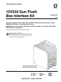
1
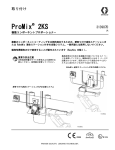
Instructions-Parts
15V534 Gun Flush
Box Interface Kit
313212A
ENG
Interfaces a Graco Gun Flush Box with a ProMix® 2KS Electronic Proportioner using a
RoboMix Fluid Station. For professional use only.
Approved for use in explosive atmospheres only when used in conjunction with ProMix
2KS Electronic Proportioners.
100 psi (0.7 MPa, 7 bar) Maximum Air Input Pressure
Important Safety Instructions
Read all warnings and instructions in this manual. For complete
warnings and instructions see your proportioning system manual
and gun flush box manual 312784. Hazard symbols refer to specific procedure risks. Save all instructions.
GFB Interface Kit shown with
two air flow switches installed
TI14275a
0359
II 2 G
#
53
Related Manuals
Contents
Related Manuals . . . . . . . . . . . . . . . . . . . . . . . . . . . 2
Overview . . . . . . . . . . . . . . . . . . . . . . . . . . . . . . . . . . 2
Installation . . . . . . . . . . . . . . . . . . . . . . . . . . . . . . . . 3
Location . . . . . . . . . . . . . . . . . . . . . . . . . . . . . . . 3
Mount the Enclosure . . . . . . . . . . . . . . . . . . . . . . 3
Install the Cable . . . . . . . . . . . . . . . . . . . . . . . . . 4
Install the Air Flow Switch . . . . . . . . . . . . . . . . . . 5
Install the Pressure Switch . . . . . . . . . . . . . . . . . 6
Install the Solenoid . . . . . . . . . . . . . . . . . . . . . . . 7
Connect the Cable to the
RoboMix Control Board . . . . . . . . . . . . . . . . 8
Connect the Gun Flush Box . . . . . . . . . . . . . . . . 9
Connect Air Supply to Module . . . . . . . . . . . . . . 9
Replace the Cover . . . . . . . . . . . . . . . . . . . . . . . 9
Ground the Enclosure . . . . . . . . . . . . . . . . . . . . . 9
Parts . . . . . . . . . . . . . . . . . . . . . . . . . . . . . . . . . . . . 11
Connect a Booth Control to the RoboMix
(to operate as a manual system) . . . . . . . . . . 12
Dimensions . . . . . . . . . . . . . . . . . . . . . . . . . . . . . . 13
Technical Data . . . . . . . . . . . . . . . . . . . . . . . . . . . . 13
Graco Standard Warranty . . . . . . . . . . . . . . . . . . . 14
Graco Information . . . . . . . . . . . . . . . . . . . . . . . . 14
Related Manuals
See the following manuals for additional information on
the ProMix 2KS and Gun Flush Box Kits.
Manual
Description
312778
ProMix 2KS Automatic System
Installation
312779
ProMix 2KS Automatic System
Operation
312780
ProMix 2KS Automatic System
Repair-Parts
312784
Gun Flush Box Kits
Overview
Gun Flush Box Interface Kit 15V534 provides electrical
and air connections to enable a ProMix 2KS RoboMix
proportioner to operate one or two gun flush boxes. See
FIG. 1 for the identification label.
Order Gun Flush Box Kit 15V826 separately (see manual 312784). Each 15V826 Kit includes one gun flush
box and related parts. The pressure switch, air flow
switch, and solenoid valve included in Gun Flush Box Kit
15V826 will be installed in this interface module.
ProMix™ 2KS
PART NO.
C
SERIES
GFB CONTROL MODULE
Intrinsically safe equipment
for Class I, Div 1, Group D, T3
US Ta = -20°C to 50°C
Install per 289833
Artwork No. 293514 Rev. B
MAX AIR WPR
SERIAL
.7
7
MPa
bar
FM08ATEX0073
II 2 G
Ex ia IIA T3
100
PSI
GRACO INC.
P.O. Box 1441
Minneapolis, MN
55440 U.S.A.
FIG. 1. GFB Interface Module Identification Label
2
313212A
Installation
Installation
Location
Install the gun flush box module enclosure (1) within 15
ft (4.5 m) of the RoboMix, to ensure that the cable (23)
will reach the RoboMix. The module is approved for use
in a hazardous location. See FIG. 1.
•
To avoid electric shock, ground all equipment.
Turn off equipment power and shut off power at
main circuit breaker before installing.
•
All electrical wiring must be done by a qualified
electrician and comply with all local codes and
regulations.
Mount the Enclosure
Do not substitute system components as this
may impair intrinsic safety.
2. Ensure that the wall and mounting hardware are
strong enough to support the weight of the equipment, fluid, hoses, and stress caused during operation.
•
To reduce the risk of serious injury, including fluid
injection, splashing, pinching or injury from moving
parts, relieve pressure before installing the kit. Follow the Pressure Relief Procedure in the ProMix
2KS Operation or Service manual.
313212A
1. See Dimensions, page 13.
3. Using the equipment as a template, mark the
mounting holes on the wall at a convenient height
for the operator and so equipment is easily accessible for maintenance.
4. Drill mounting holes in the wall. Install anchors as
needed.
5. Bolt equipment securely.
3
Installation
Install the Cable
3. Connect the cable wires to the left side of the terminal strip (12), as indicated by the label (20). See FIG.
2 and Table 1.
1. Loosen the captive screws and remove the front
cover from the enclosure.
20
2. The cable (23) has bare wires at both ends. Thread
the shortest end (4 in. [102 mm]) into the enclosure
through the strain relief bushing (7). See FIG. 2.
12
7
TI14279a
FIG. 2. Connect Cable to Terminal Strip
4. Connect the other end of the cable (5 in. [127 mm])
to pins 1-4 and 7-10 of the 10 position connector
(24) and pins 1-4 of the 6 position connector, as
shown in the Cable (23) Wire Harness Detail on
page 11.
Table 1: Terminal Strip Wire Connections
Pin No.
4
Cable Wire Colors
Pin No.
Switch Wires
1
Black
1
Air Flow Switch 1 +
2
White
2
Air Flow Switch 1 -
3
Red
3
Air Flow Switch 2 +
4
Green
4
Air Flow Switch 2 -
5
Orange
5
Pressure Switch 1 +
6
Blue
6
Pressure Switch 1 -
7
White/Black
7
Pressure Switch 2 +
8
Red/Black
8
Pressure Switch 2 -
9
Green/Black
9
Solenoid 1, + (12V), Red
10
Orange/Black
10
Solenoid 1, - (COM), Black
11
Blue/Black
11
Solenoid 2, + (12V), Red
12
Red/White
12
Solenoid 2, - (COM), Black
313212A
Installation
Install the Air Flow Switch
NOTE: The GFB Interface Module Kit does not include
an air flow switch (AFS). The AFS is supplied with the
gun flush box kit. Install the AFS in the interface module
as follows.
2. Connect the wires from AFS#1 to the right side of
the terminal strip (12) pins 1 (+) & 2 (-), as indicated
by the label (21). See FIG. 4 and Table 1.
12
21
1. Each gun flush box kit includes one air flow switch
(AFS). The GFB interface module can accommodate 1 or 2 air flow switches. Install the switch(es) in
the right side of the enclosure. See FIG. 3.
1
AFS is part of gun flush box kit; not included
with GFB Interface Kit.
AFS#1
1
AFS#2
1
TI14279a
FIG. 4. Connect Air Flow Switch to Terminal Strip
3. If using a second gun flush box, connect the wires
from AFS#2 to the right side of the terminal strip
(12) pins 3 (+) & 4 (-), as indicated by the label (21).
See FIG. 4 and Table 1.
TI14281a
FIG. 3. Install Air Flow Switch (two shown)
313212A
5
Installation
Install the Pressure Switch
NOTE: The GFB Interface Module Kit does not include a
pressure switch (PS). The pressure switch is supplied
with the gun flush box kit. Install the pressure switch in
the interface module as follows.
2. Connect the wires from PS#1 to the right side of the
terminal strip (12) pins 5 (+) & 6 (-), as indicated by
the label (21). See FIG. 6 and Table 1.
12
21
1. Each gun flush box kit includes one pressure switch
(PS). The GFB interface module can accommodate
1 or 2 pressure switches. Install the switch(es) in the
left side of the enclosure. See FIG. 5.
1
Pressure switch is part of gun flush box kit;
not included with GFB Interface Kit.
1
PS#1
TI14279a
FIG. 6. Connect Pressure Switch to Terminal Strip
3. If using a second gun flush box, connect the wires
from PS#2 to the right side of the terminal strip (12)
pins 7 (+) & 8 (-), as indicated by the label (21). See
FIG. 6 and Table 1.
PS#2
1
TI14282a
FIG. 5. Install Pressure Switch (two shown)
6
313212A
Installation
Install the Solenoid
NOTE: The GFB Interface Module Kit does not include a
solenoid (SO). The solenoid is supplied with the gun
flush box kit. Install the solenoid in the interface module
as follows.
2. Connect the wires from SO#1 to the right side of the
terminal strip (12), as indicated by the label (21); red
(+12V) to pin 9, black (COM) to pin 10. See FIG. 8
and Table 1.
12
21
1. Each gun flush box kit includes one solenoid (SO).
The GFB interface module can accommodate 1 or 2
solenoids. Install the solenoid(s) on the manifold at
the bottom rear of the enclosure. See FIG. 7.
NOTE: See Parts on page 11. If you are using two gun
flush boxes, remove the two sealing screws (4) from the
solenoid manifold (8) before installing SO#2. Also
remove the plug (5) from the connector (15).
1
TI14279a
Solenoid is part of gun flush box kit; not
included with GFB Interface Kit.
FIG. 8. Connect Solenoid to Terminal Strip
3. If using a second gun flush box, connect the wires
from SO#2 to the right side of the terminal strip (12),
as indicated by the label (21); red (+12V) to pin 11,
black (COM) to pin 12. See FIG. 8 and Table 1.
1
SO#1
1
SO#2
TI14282a
FIG. 7. Install Solenoid (two shown)
313212A
7
Installation
Connect the Cable to the
RoboMix Control Board
NOTICE
To avoid damaging circuit board when servicing, wear
grounding strap on wrist and ground appropriately.
1. See the ProMix 2KS Repair-Parts manual. Open the
RoboMix to access the control board.
2. Connect the 10 position connector (24) to J1 on the
control board. See FIG. 9.
J1 Pins 1-4, 7-10
(10 position
Connector 24)
FIG. 9: RoboMix Control Board J1 Connections
3. Connect the 6 position connector (25) to J8 on the
control board. See FIG. 10
J8 Pins 1-4
(6 position Connector 25)
FIG. 10: RoboMix Control Board J8 Connections
8
313212A
Installation
Connect the Gun Flush Box
Replace the Cover
NOTE: Use 5/32 in. (4 mm) OD tubing to connect the
gun flush box air ports to the interface module air ports,
as follows. See FIG. 12.
Reinstall the cover on the enclosure and secure with the
four captive screws.
1. From the P port to the air supply.
Ground the Enclosure
2. From the A port to the pressure switch air input.
Connect a ground wire (Y) from the enclosure’s ground
screw (6) to a true earth ground. See FIG. 11.
3. From the C port to the gun flush box solenoid output.
4. From the S port to the atomizing air safety shutoff
valve pilot port. See the gun flush box manual for
details on the safety shutoff valve.
Y
6
5. From the AFS to the atomizing air safety shutoff
valve IN port. See the gun flush box manual for
details on the safety shutoff valve.
TI14277a
Connect Air Supply to Module
FIG. 11. Ground the Enclosure
Connect a 1/4 in. (6 mm) OD tube between a clean, dry
air supply (filtered to 10 microns) and the module air
inlet fitting (13). See Parts on page 11.
GUN FLUSH BOX
P
A
INTERFACE MODULE
P
A
C
S
C
AFS
S
AIR SAFETY
SHUTOFF VALVE
C
IN
P
TI14278a
TI13110b
FIG. 12: Gun Flush Box to Interface Module Air Connections
313212A
9
Installation
10
313212A
Parts
Parts
20
1
21
16
9
6
10
11
12
7
TI14279a
3
18
13
14
8
1
If using two gun flush boxes, remove
item 5 and two of item 4.
1 (Ref)
15
1
TI14280a
5
4
1
12 (Ref)
1
2
3
4
5
6
7
8
9
10
11
12
23
24
AIR FLOW SWITCH #1 + (BLK)
AIR FLOW SWITCH #1 - (WHT)
AIR FLOW SWITCH #2 + (RED)
AIR FLOW SWITCH #2 - (GRN)
PRESSURE SWITCH #1 + (ORG)
PRESSURE SWITCH #1 - (BLU)
PRESSURE SWITCH #2 + (WHT/BLK)
PRESSURE SWITCH #2 - (RED/BLK)
SOLENOID #1 +12 (GRN/BLK)
SOLENOID #1 COM (ORG/BLK)
SOLENOID #2 +12 (BLU/BLK)
SOLENOID #2 COM (RED/WHT)
1
2
3
4
5
6
7
8
9
10
1
2
3
4
5
6
Cable (23) Wire Harness Detail
25
Ref.
No.
1
3
4
5
6
7
8
9
10
11
12
Part No. Description
15V531
118435
121628
113279
116343
114421
15V533
116457
116804
116459
116458
313212A
ENCLOSURE, GFB module
GROMMET
SCREW, self-sealing
PLUG, fitting, tube
SCREW, ground
BUSHING, strain relief
MANIFOLD, GFB solenoid
RAIL; 3 in. (76 mm)
BLOCK, end, terminal
COVER, end, terminal
TERMINAL, rail mount
Qty
1
1
4
1
1
1
1
1
2
2
12
Ref.
No.
13
14
15
16
18
19
20
21
23
24
25
Part No. Description
Qty
1
115671 CONNECTOR, tube; 1/4 in. OD
1
C06061 MUFFLER
4
111328 CONNECTOR, tube; 5/32 in. OD
2
113045 SCREW, machine, truss-hd
2
103832 SCREW, machine
1
n/a
TUBE, nylon; 1.2 in. (30 mm)
1
293494 LABEL, cable wire connections
1
293495 LABEL, switch wire connections
1
15V819 CABLE, GFB interface
1
15V409 CONNECTOR, 10 position
1
15G795 CONNECTOR, 6 position
11
Connect a Booth Control to the RoboMix (to operate as a manual system)
Connect a Booth Control to the RoboMix (to operate
as a manual system)
To use the RoboMix as a manual system, order the
15V350 Booth Control Kit and connect as follows. The
kit includes a booth control module, wall bracket, and 50
ft (15.25 m) cable.
1. See FIG. 13. Mount the booth control in a convenient
location near the RoboMix. Bring the cable to the
RoboMix and thread it through the cable path at the
back.
NOTICE
To avoid damaging circuit board when servicing, wear
grounding strap on wrist and ground appropriately.
2. See the ProMix 2KS Repair-Parts manual. Open the
RoboMix to access the control board.
3. Connect the cable to J7 on the control board. Close
up the RoboMix and return to operation.
Cable Path
TI12511a
Booth Control
J7. Plug In for
Booth Control
Cable
Booth Control Cable
RoboMix Control Board
RoboMix
TI15110a
FIG. 13. Connect a Booth Control to the RoboMix
12
313212A
Dimensions
Dimensions
4.00 in.
(101.6 mm)
4.00 in.
(101.6 mm)
7.50 in.
(190.5 mm)
TI14276a
6.75 in.
(171.5 mm)
Mounting Holes
6.28 in.
(159.5 mm)
TI14278a
Technical Data
Maximum Air Input Pressure . . . . . . . . . . . . . . . . . . . . .
Air Inlet Size . . . . . . . . . . . . . . . . . . . . . . . . . . . . . . . . . .
Air Outlet Size. . . . . . . . . . . . . . . . . . . . . . . . . . . . . . . . .
Weight . . . . . . . . . . . . . . . . . . . . . . . . . . . . . . . . . . . . . .
313212A
100 psi (0.7 MPa, 7 bar)
1/4 in. (6 mm) OD tube connector
5/32 in. (4 mm) OD tube connectors
6.69 lb (3.03 kg)
13
Graco Standard Warranty
Graco warrants all equipment referenced in this document which is manufactured by Graco and bearing its name to be free from defects in
material and workmanship on the date of sale to the original purchaser for use. With the exception of any special, extended, or limited warranty
published by Graco, Graco will, for a period of twelve months from the date of sale, repair or replace any part of the equipment determined by
Graco to be defective. This warranty applies only when the equipment is installed, operated and maintained in accordance with Graco’s written
recommendations.
This warranty does not cover, and Graco shall not be liable for general wear and tear, or any malfunction, damage or wear caused by faulty
installation, misapplication, abrasion, corrosion, inadequate or improper maintenance, negligence, accident, tampering, or substitution of
non-Graco component parts. Nor shall Graco be liable for malfunction, damage or wear caused by the incompatibility of Graco equipment with
structures, accessories, equipment or materials not supplied by Graco, or the improper design, manufacture, installation, operation or
maintenance of structures, accessories, equipment or materials not supplied by Graco.
This warranty is conditioned upon the prepaid return of the equipment claimed to be defective to an authorized Graco distributor for verification of
the claimed defect. If the claimed defect is verified, Graco will repair or replace free of charge any defective parts. The equipment will be returned
to the original purchaser transportation prepaid. If inspection of the equipment does not disclose any defect in material or workmanship, repairs will
be made at a reasonable charge, which charges may include the costs of parts, labor, and transportation.
THIS WARRANTY IS EXCLUSIVE, AND IS IN LIEU OF ANY OTHER WARRANTIES, EXPRESS OR IMPLIED, INCLUDING BUT NOT LIMITED
TO WARRANTY OF MERCHANTABILITY OR WARRANTY OF FITNESS FOR A PARTICULAR PURPOSE.
Graco’s sole obligation and buyer’s sole remedy for any breach of warranty shall be as set forth above. The buyer agrees that no other remedy
(including, but not limited to, incidental or consequential damages for lost profits, lost sales, injury to person or property, or any other incidental or
consequential loss) shall be available. Any action for breach of warranty must be brought within two (2) years of the date of sale.
GRACO MAKES NO WARRANTY, AND DISCLAIMS ALL IMPLIED WARRANTIES OF MERCHANTABILITY AND FITNESS FOR A
PARTICULAR PURPOSE, IN CONNECTION WITH ACCESSORIES, EQUIPMENT, MATERIALS OR COMPONENTS SOLD BUT NOT
MANUFACTURED BY GRACO. These items sold, but not manufactured by Graco (such as electric motors, switches, hose, etc.), are subject to
the warranty, if any, of their manufacturer. Graco will provide purchaser with reasonable assistance in making any claim for breach of these
warranties.
In no event will Graco be liable for indirect, incidental, special or consequential damages resulting from Graco supplying equipment hereunder, or
the furnishing, performance, or use of any products or other goods sold hereto, whether due to a breach of contract, breach of warranty, the
negligence of Graco, or otherwise.
FOR GRACO CANADA CUSTOMERS
The Parties acknowledge that they have required that the present document, as well as all documents, notices and legal proceedings entered into,
given or instituted pursuant hereto or relating directly or indirectly hereto, be drawn up in English. Les parties reconnaissent avoir convenu que la
rédaction du présente document sera en Anglais, ainsi que tous documents, avis et procédures judiciaires exécutés, donnés ou intentés, à la suite
de ou en rapport, directement ou indirectement, avec les procédures concernées.
Graco Information
For the latest information about Graco products, visit www.graco.com.
TO PLACE AN ORDER, contact your Graco distributor or call to identify the nearest distributor.
Phone: 612-623-6921 or Toll Free: 1-800-328-0211 Fax: 612-378-3505
All written and visual data contained in this document reflects the latest product information available at the time of publication.
Graco reserves the right to make changes at any time without notice.
This manual contains English. MM 313212
Graco Headquarters: Minneapolis
International Offices: Belgium, China, Japan, Korea
GRACO INC. P.O. BOX 1441 MINNEAPOLIS, MN 55440-1441
Copyright 2009, Graco Inc. is registered to ISO 9001
www.graco.com