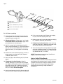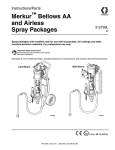
1
Repair/Parts
™
Merkur
Bellows
Displacement Pump
312793H
EN
For pumping isocyanates, UV coatings, and other moisture-sensitive materials. For
professional use only.
See page 6 for model information, including maximum working pressures.
Important Safety Instructions
Read all warnings and instructions in this manual.
For complete warnings and instructions see your
pump or package manual. Hazard symbols refer to
specific procedure risks. Save these instructions.
ti14532a
Related Manuals
Contents
Related Manuals . . . . . . . . . . . . . . . . . . . . . . . . . . .
Warnings . . . . . . . . . . . . . . . . . . . . . . . . . . . . . . . . .
Important Two-Component Material Information .
Isocyanate Conditions . . . . . . . . . . . . . . . . . . . . .
Material Self-ignition . . . . . . . . . . . . . . . . . . . . . .
Keep Components A and B Separate . . . . . . . . .
Moisture Sensitivity of Isocyanates . . . . . . . . . . .
Changing Materials . . . . . . . . . . . . . . . . . . . . . . .
Models . . . . . . . . . . . . . . . . . . . . . . . . . . . . . . . . . . .
Component Identification . . . . . . . . . . . . . . . . . . . .
2
3
5
5
5
5
5
5
6
7
Repair . . . . . . . . . . . . . . . . . . . . . . . . . . . . . . . . . . . . 8
General Information . . . . . . . . . . . . . . . . . . . . . . . 8
Preparation . . . . . . . . . . . . . . . . . . . . . . . . . . . . . 8
Replace the Bellows . . . . . . . . . . . . . . . . . . . . . . 9
Complete Pump Repair . . . . . . . . . . . . . . . . . . . 11
Parts . . . . . . . . . . . . . . . . . . . . . . . . . . . . . . . . . . . . 16
Repair Kits . . . . . . . . . . . . . . . . . . . . . . . . . . . . . . . 20
Optional Kits . . . . . . . . . . . . . . . . . . . . . . . . . . . . . . 21
Accessories . . . . . . . . . . . . . . . . . . . . . . . . . . . . . . 21
Dimensions . . . . . . . . . . . . . . . . . . . . . . . . . . . . . . . 22
Technical Data . . . . . . . . . . . . . . . . . . . . . . . . . . . . 23
Graco Standard Warranty . . . . . . . . . . . . . . . . . . . 24
Graco Information . . . . . . . . . . . . . . . . . . . . . . . . . 24
Related Manuals
2
Manual
Description
312795
Merkur Bellows Pump Assembly
312796
NXT™ Air Motor
312799
Merkur Bellows Spray Packages, AA and
Airless
312798
Merkur Electrostatic Spray Packages
312793H
Warnings
Warnings
The following warnings are for the setup, use, grounding, maintenance, and repair of this equipment. The exclamation point symbol alerts you to a general warning and the hazard symbols refer to procedure-specific risks. When
these symbols appear in the body of this manual, refer back to these Warnings. Product-specific hazard symbols and
warnings not covered in this section may appear throughout the body of this manual where applicable.
WARNING
WARNING
FIRE AND EXPLOSION HAZARD
Flammable fumes, such as solvent and paint fumes, in work area can ignite or explode. To help prevent
fire and explosion:
•
•
•
•
Use equipment only in well ventilated area.
Eliminate all ignition sources; such as pilot lights, cigarettes, portable electric lamps, and plastic drop
cloths (potential static arc).
Keep work area free of debris, including solvent, rags and gasoline.
Do not plug or unplug power cords, or turn power or light switches on or off when flammable fumes
are present.
•
Ground all equipment in the work area. See Grounding instructions.
•
Use only grounded hoses.
•
Hold gun firmly to side of grounded pail when triggering into pail.
•
•
If there is static sparking or you feel a shock, stop operation immediately. Do not use equipment
until you identify and correct the problem.
Keep a working fire extinguisher in the work area.
SKIN INJECTION HAZARD
High-pressure fluid from gun, hose leaks, or ruptured components will pierce skin. This may look like just
a cut, but it is a serious injury that can result in amputation. Get immediate surgical treatment.
•
Do not spray without tip guard and trigger guard installed.
•
Engage trigger lock when not spraying.
•
Do not point gun at anyone or at any part of the body.
•
Do not put your hand over the spray tip.
•
Do not stop or deflect leaks with your hand, body, glove, or rag.
•
312793H
Follow the Pressure Relief Procedure when you stop spraying and before cleaning, checking, or
servicing equipment.
•
Tighten all fluid connections before operating the equipment.
•
Check hoses and couplings daily. Replace worn or damaged parts immediately.
3
Warnings
WARNING
WARNING
EQUIPMENT MISUSE HAZARD
Misuse can cause death or serious injury.
•
Do not operate the unit when fatigued or under the influence of drugs or alcohol.
•
Do not exceed the maximum working pressure or temperature rating of the lowest rated system component. See Technical Data in all equipment manuals.
•
Use fluids and solvents that are compatible with equipment wetted parts. See Technical Data in all
equipment manuals. Read fluid and solvent manufacturer’s warnings. For complete information about
your material, request MSDS from distributor or retailer.
•
Do not leave the work area while equipment is energized or under pressure. Turn off all equipment
and follow the Pressure Relief Procedure when equipment is not in use.
•
Check equipment daily. Repair or replace worn or damaged parts immediately with genuine manufacturer’s replacement parts only.
•
Do not alter or modify equipment.
•
Use equipment only for its intended purpose. Call your distributor for information.
•
Route hoses and cables away from traffic areas, sharp edges, moving parts, and hot surfaces.
•
Do not kink or over bend hoses or use hoses to pull equipment.
•
Keep children and animals away from work area.
•
Comply with all applicable safety regulations.
MOVING PARTS HAZARD
Moving parts can pinch, cut or amputate fingers and other body parts.
•
Keep clear of moving parts.
•
Do not operate equipment with protective guards or covers removed.
•
Pressurized equipment can start without warning. Before checking, moving, or servicing equipment,
follow the Pressure Relief Procedure and disconnect all power sources.
SUCTION HAZARD
Powerful suction could cause serious injury.
•
Never place hands near the pump fluid inlet when pump is operating or pressurized.
TOXIC FLUID OR FUMES HAZARD
Toxic fluids or fumes can cause serious injury or death if splashed in the eyes or on skin, inhaled, or swallowed.
•
Read MSDSs to know the specific hazards of the fluids you are using.
•
Store hazardous fluid in approved containers, and dispose of it according to applicable guidelines.
•
Always wear chemically impermeable gloves when spraying, dispensing, or cleaning equipment.
PERSONAL PROTECTIVE EQUIPMENT
You must wear appropriate protective equipment when operating, servicing, or when in the operating area
of the equipment to help protect you from serious injury, including eye injury, hearing loss, inhalation of
toxic fumes, and burns. This equipment includes but is not limited to:
4
•
Protective eyewear, and hearing protection.
•
Respirators, protective clothing, and gloves as recommended by the fluid and solvent manufacturer.
312793H
Important Two-Component Material Information
Important Two-Component Material Information
Isocyanate Conditions
Spraying or dispensing materials containing isocyanates creates potentially harmful mists, vapors, and
atomized particulates.
Read material manufacturer’s warnings and material
MSDS to know specific hazards and precautions
related to isocyanates.
Prevent inhalation of isocyanate mists, vapors, and
atomized particulates by providing sufficient ventilation in the work area. If sufficient ventilation is not
available, a supplied-air respirator is required for
everyone in the work area.
To prevent contact with isocyanates, appropriate personal protective equipment, including chemically
impermeable gloves, boots, aprons, and goggles, is
also required for everyone in the work area.
Moisture Sensitivity of
Isocyanates
Isocyanates (ISO) are catalysts used in two component
coatings. ISO will react with moisture (such as humidity)
to form small, hard, abrasive crystals, which become
suspended in the fluid. Eventually a film will form on the
surface and the ISO will begin to gel, increasing in viscosity. If used, this partially cured ISO will reduce performance and the life of all wetted parts.
NOTE: The amount of film formation and rate of crystallization varies depending on the blend of ISO, the
humidity, and the temperature.
To prevent exposing ISO to moisture:
•
Always use a sealed container with a desiccant
dryer in the vent, or a nitrogen atmosphere. Never
store ISO in an open container.
•
Use moisture-proof hoses specifically designed for
ISO, such as those supplied with your system.
•
Never use reclaimed solvents, which may contain
moisture. Always keep solvent containers closed
when not in use.
•
Never use solvent on one side if it has been contaminated from the other side.
•
Always lubricate threaded parts with ISO pump oil
or grease when reassembling.
Material Self-ignition
Some materials may become self-igniting if applied
too thickly. Read material manufacturer’s warnings
and material MSDS.
Keep Components A and B
Separate
Cross-contamination can result in cured material in
fluid lines which could cause serious injury or damage equipment. To prevent cross-contamination of
the equipment’s wetted parts, never interchange
component A (isocyanate) and component B (resin)
parts.
312793H
Changing Materials
•
When changing materials, flush the equipment multiple times to ensure it is thoroughly clean.
•
Always clean the fluid inlet strainers after flushing.
•
Check with your material manufacturer for chemical
compatibility.
Most materials use ISO on the A side, but some use ISO
on the B side.
5
Models
Models
Check your displacement pump’s identification marking (ID) for the 6-digit part
number. Use the following matrix to define the construction of your displacement pump, based on the six digits. For example, displacement pump Part No.
LB100A represents a 303 stainless steel bellows style displacement pump,
100 cc, with 3 UHMWPE and 2 PTFE v-packings.
ID
To order replacement parts, see Parts section starting on page 16. The digits
in the matrix do not correspond to the reference numbers in the Parts drawings
and lists.
L
First
Digit
L
B
ti15221a
B
100
A
Second Digit
(Material)
Third, Fourth, and Fifth
Digits
(Displacement Pump
Volume Per Cycle in
cc)
Sixth Digit
(Packings/Seals)
Bellows Style
(Lower)
050
A
V-Packings (3 UHMWPE, 2 PTFE)
100
B
U-Cup Seal
150
Series
Maximum Working
Pressure
psi (MPa, bar)
Fluid Inlet
Fluid Outlet
LB050A
LB050B
A
4500 (33.1, 310
3/4 in. npt
3/8 in. npt
LB100A
LB100B
A
3600 (24.8, 248)
3/4 in. npt
3/8 in. npt
LB150A
LB150B
A
2400 (16.5, 165)
1 in. npt
3/4 in. npt
Part Number
6
312793H
Component Identification
Component Identification
A
B
C
D
E
F
G
H
J
ti14532a
FIG. 1. Component Identification
Key:
A Connecting Rod
B Top Cap
C Pump Fluid Inlet
D Bellows Chamber
E Packing Nut
F Cylinder
G Pump Fluid Outlet
H Pump Adapter
J Foot Cap
312793H
7
Repair
Repair
General Information
NOTE: Reference numbers and letters in parentheses
in the text refer to the callouts in the figures.
Always use Genuine Graco Parts and Accessories,
available from your Graco distributor. If you supply your
own accessories, be sure they are adequately sized and
pressure rated for your system.
Preparation
6. Use a 5 mm hex wrench to loosen the screws (10)
on the top cap.
7. Hold the coupling nut
with a wrench. Use
another wrench to turn
the motor shaft. To
avoid damage to the
top cap and the
D-shaped seal, do not
turn the coupling nut.
hold
turn
10
ti12815a
8. Lower the coupling nut
and remove the coupling collars.
ti14531a
Follow all warnings and instructions in your pump manual for the following preliminary steps:
1. Flush the equipment.
2. Stop the pump close to the middle of the stroke.
3. Relieve the pressure.
4. Disconnect the air and fluid hoses and the ground
wire.
5. Remove the shield.
ti15365a
FIG. 2. Remove coupling collars.
9. Push up the motor shaft. Remove the coupling nut.
10. Cart Mount: Tilt the cart onto its back to service the
displacement pump.
NOTE: If the overflow chamber (optional accessory)
contains fluid, unscrew the bottle (103) and discard. See
FIG. 4. If it has not been used, the bottle can remain
attached to the cap.
To avoid the buildup of electrostatic charge, do not
rub the plastic bottle with a dry cloth while it is
attached to the pump. Remove the bottle to clean, if
needed.
ti15253a
FIG. 3. Tilt pump for repair.
8
312793H
Repair
Replace the Bellows
5. Use a socket to remove the foot cap (42). Remove
and discard the o-ring (41).
Disassemble Bellows and Chamber
6. Hold the hex on the connecting rod (14) with a
19 mm (3/4 in.) wrench. Brace against tie rod or
bench so it cannot turn. Use a socket to loosen the
piston/rod assembly.
NOTICE
To avoid damage to the top cap and D-shaped seal,
never apply torque to the connecting rod.
1. Follow all steps under Preparation, page 8.
2. Use a 5 mm hex wrench to remove the three screws
(10), then remove the shield mount spacer (9) and
the top cap (8). Remove and discard the bellows
chamber o-ring (12).
3. Leave the overflow chamber attached to the top cap
unless it needs to be replaced.
turn
hold
ti15252a
FIG. 5. Hold connecting rod steady.
4. If replacing overflow chamber: Unscrew the bottle
(103) if not already removed, then remove the lid
(101) from the fitting (104). Discard the cup and lid.
Use a socket to remove the retaining nut (105) in
the top cap (8). Remove and discard the D-shaped
seal (106). Leave the fitting (104) attached to the
top cap (8) unless it needs to be replaced.
7. See FIG. 6. Pull the connecting rod (14) and bellows
(7) out of the top of the bellows chamber (1). Leave
the bellows chamber (1) attached to the packing
nut.
8. Remove the bellows bushing (6) and the damaged
bellows (7).
9. Remove the snap bushing (3). Remove and discard
the o-rings (4, 5).
104
105
106
8
101
102
103
ti15254a
FIG. 4. Overflow chamber
312793H
9
Repair
Reassemble Bellows and Chamber
seal (106) on the connecting rod (14). Hold connecting rod with 19 mm (3/4 in.) wrench. Install and
tighten the retaining nut (105). Torque to 100-120
in-lb (11-14 N•m). Do not overtighten.
1. Slide the bellows bushing (6) and new bellows (7)
on the connecting rod (14).
2. Install new o-rings (4 and 5) into snap bushing.
Grease and install snap bushing (3) on end of bellows and snap into place.
8. Install a new foot cap o-ring (41). Grease and install
the foot cap (42). Torque to 54-66 ft-lb (73-89 N•m).
9. Push up on the motor shaft. Slide on the coupling
nut (55). Install the coupling collars (56).
3. Put the bellows o-ring (12) loosely around the bellows (7). Push the connecting rod (14), with fully
assembled bellows (7) into the bellows chamber (1).
Hand tighten the connecting rod.
10. Hold connecting rod with 19 mm (3/4 in.) wrench.
Install and tighten the coupling nut. Torque to 75-80
ft-lb (138-146 N•m).
4. Hold the hex on the connecting rod (14) and use a
torque wrench to turn the piston (45). Torque to
74-86 ft-lb (100-117 N•m).
11. If Replacing Overflow Chamber: Insert the o-ring
(102) into the lid (101). Tighten the new bottle (103)
with lid (101) attached, to the fitting (104).
5. Make sure the o-ring (12) is against the top of the
bellows. Push the connecting rod (14) and bellows
(7) snugly into the bellows chamber (1).
12. Turn connecting rod (14) to align holes in top cap (8)
with holes on bellows chamber (1) so the D-flat in
the top cap faces the front of the pump. Reattach
the top cap (8) and shield mount spacer (9). Torque
screws (10) to 100-120 in-lb (11-14 N•m).
6. Set top cap (8) on the connecting rod (14). Do not
tighten.
7. If Replacing Overflow Chamber: Order Kit
24E298. (See page 21.) Install the new D-shaped
1
Apply grease.
2
Apply thread lubricant.
3
Torque to 100-120 in-lb (11-14 N•m).
4
Torque to 54-66 ft-lb (73-89 N•m).
5
1
42
14
2
5
45
3
4
7
Torque to 74-86 ft-lb (100-117 N•m).
10
2
41
1
9
12
1
3
4
1
5
1
6
8
ti14533a
FIG. 6. Replace bellows.
10
312793H
Repair
Complete Pump Repair
Disassembly
1. Follow all steps under Preparation, page 8.
2. Use a socket to remove the foot cap (42). Remove
and discard the o-ring (41).
3. Use a 5 mm hex wrench to loosen the three screws
(10) on the top cap. Lift the air motor shaft to
remove the top cap (8) and the shield mount spacer
(9) from the bellows chamber.
4. Hold the hex on the connecting rod (14) with a 19
mm (3/4 in.) wrench so it cannot turn. Use a socket
to loosen the piston/rod assembly. See FIG. 5.
12. V-Packing Models: Remove the glands (23, 26),
throat packings (24, 25), and spring (22). See FIG.
10, page 12.
13. U-Cup Models: Use an o-ring pick or pliers to
remove the spring clip (51), the u-cup (50), and the
bearing (49). FIG. 11, page 13.
14. Remove and discard the packing nut top o-ring (2)
and bottom o-ring (21).
15. Put the hex of the piston rod (31) in a vise. Use a
1/2 in. hex wrench to remove the flow-through nut
(44) from the bottom of the piston (45).
16. Remove the o-ring (32) and seat (46). Remove from
vise and tip out the check ball (47).
5. Pull the piston/rod assembly out of the bottom of the
cylinder (27).
1/2 in. hex
1
6. V-Packing Models: Remove the piston packings
(37, 39), glands (38, 40), and spring (35). See FIG.
14, page 14.
7. U-Cup Models: Remove the bearing (52), u-cup
(53), and washer (54). See FIG. 13, page 13.
2
44
46
32
1
47
1
Apply lubricant.
2
Torque to 74-86 ft-lb
(100-117 N•m).
8. Models with overflow chamber: If overflow chamber needs to be replaced, see Replace the Bellows, page 9. If overflow chamber is fine, leave it
attached to the top cap.
45
31
9. Remove the connecting rod (14) and bellows (7).
10. Use a 5 mm allen wrench to remove the three
screws (17) and washers (18), then remove the bellows chamber (1). Remove and discard the bellows
chamber o-ring (12).
ti15410a
FIG. 7. Outlet check.
11. Use a 54 mm (2 1/8 in.) socket wrench to remove
the packing nut (20).
312793H
11
Repair
17. Put the hex of the piston (45) in a vise, then use a
23 mm socket to remove the piston rod (31).
2. Install check ball (34) and seat (33) in the top of the
piston. Grease and install new o-ring (32).
18. Remove the piston o-ring (32) and seat (33).
Remove from vise and tip out the check ball (34)
and spring (36).
3. With hex of piston (45) still in vise, apply thread
lubricant and then use a socket to reattach the displacement rod (31). Torque to 91-109 ft-lb
(123-148 N•m).
1
Apply grease.
2
Apply thread lubricant.
3
Torque to 91-109 ft-lb
(123-148 N•m).
4. Clamp the hex of piston rod in vise. Install new
check ball (47) and seat (46) in the bottom of the
piston. Grease and install new o-ring (32).
31
2
32
33
5. Grease and reinstall the flow-through nut (44).
Torque to 74-86 ft-lb (100-117 N•m).
3
1
6. Place the packing nut (20) upside down on the
bench so packings will align properly.
34
V-Packing Models: Lubricate and install the female
gland (26), new v-packings, 24, 25) and the male
gland (23) in the packing nut. Lips must face up,
so they will face toward the cylinder when the
packing nut is installed. Push packings all the way
in.
36
45
.
ti14536a
FIG. 8. Piston check.
19. If the bellows is damaged, see Replace the Bellows, page 9. If not, leave the bellows attached to
the connecting rod.
2
1
23
1
25
24
1
26
1
2
Reassembly
1. Clamp the hex of the piston (45) in a vise. Install
new spring (36) on the ball stop.
1
Apply lubricant.
2
Lips face up
(toward cylinder
when installed).
20
ti15255a
FIG. 10. Throat v-packings
ti15496a
FIG. 9. Ball stop spring
12
U-Cup Models: Lubricate and install the bearing
(49), the u-cup packing (50), and the spring clip
(51). U-cup must face up, so it will face toward
the cylinder when the packing nut is installed.
312793H
Repair
1
Apply grease.
2
U-cup faces up
(toward cylinder
when installed).
1
2
1
11. V-Packing Models: Install new piston spring (35).
Lubricate and install male gland (40), new piston
packings (37, 39), and female gland (38) on the displacement rod (31). Lips must face toward the
cylinder.
51
1
50
12. U-Cup Models: Lubricate and install the washer
(54), u-cup (53), and bearing (52). U-cup must face
toward the cylinder.
49
20
1
Apply lubricant.
2
Lips face toward
cylinder.
ti15259a
FIG. 11. U-Cup throat seal
7. Install the top o-ring (2) and the bottom o-ring (21)
on the packing nut (20).
53
1
8. V-Packing Models: Install the spring (22) in the top
of the cylinder (27).
9. Grease and reattach the packing nut (20). Torque to
54-66 ft-lb (73-89 N•m).
10. Use screws (17) and washers (18) to reattach the
bellows chamber (1). Align the screws so the inlet
fitting does not interfere with the tie rods. Torque
screws (17) to 100-120 in-lb (11-14 N•m).
1
Apply grease.
2
Apply thread lubricant.
3
Torque to 100-120 in-lb (11-14 N•m).
4
Torque to 54-66 ft-lb (73-89 N•m).
20
2
1
2
54
1
52
1
ti15260a
FIG. 13. U-Cup piston seal
4
22
1
1
21
18 (x 3)
17 (x 3)
1
ti14534a
3
FIG. 12. Bellows chamber and packing nut.
312793H
13
Repair
31
2
4
45
35
1
40
1
37
1
5
38
1
Apply grease.
2
Apply thread lubricant.
3
Torque to 100-120 in-lb (11-14 N•m).
4
Torque to 91-109 ft-lb (123-148 N•m).
5
Lips face toward cylinder.
5
1
1
39
1
41
3
2
42
ti14535a
FIG. 14. Piston v-packings
13. Grease the outside of the displacement rod shaft
and the piston, near the hexes. Push the rod and
the piston into the cylinder (27).
14. If Replacing Bellows: Follow steps 1 and 2 under
Reassemble Bellows and Chamber, page 10, to
put new bellows on connecting rod.
15. See FIG. 6, page 10. Put the bellows o-ring (12)
loosely around the bellows (7). Push the connecting
rod (14), with fully assembled bellows (7) into the
bellows chamber (1). Hand tighten the connecting
rod.
20. Push up on the motor shaft. Slide on the coupling
nut (55). Install the coupling collars (56).
21. Hold air motor shaft. Install and tighten the coupling
nut. Torque to 75-80 ft-lb (138-146 N•m).
22. If Replacing Overflow Chamber: Insert the o-ring
(102) into the lid (101). Tighten the new bottle (103)
with lid (101) attached, to the fitting (104).
23. Turn connecting rod (14) to align holes in top cap (8)
with holes on bellows chamber (1). Reattach the top
cap (8) and shield mount spacer (9). Torque screws
(10) to 100-120 in-lb (11-14 N•m).
16. Hold the hex on the connecting rod (14) and use a
torque wrench to turn the piston (45). Torque to
74-86 ft-lb (100-117 N•m).
NOTE: The overflow chamber fits best if the D flat is
aligned to the front of the pump.
17. Set top cap (8) on the connecting rod (14). Do not
tighten.
Inlet or Outlet Fitting Repair
18. If Replacing Overflow Chamber: Order Kit
24E298. (See page 21.) Install the new D-shaped
seal (106) on the connecting rod (14). Hold connecting rod with 19 mm (3/4 in.) wrench. Install and
tighten the retaining nut (105). Torque to 100-120
in-lb (11-14 N•m). Do not overtighten.
Remove and replace the inlet or outlet fitting only if damaged. Replace one or both o-rings if a leak or seepage
is present and every time a fitting is removed. To reassemble, grease the o-ring and apply high-strength
thread locker to the fitting. Torque to 54-66 ft-lb
(73-89 N•m).
19. Install a new foot cap o-ring (41). Grease and install
the foot cap (42). Torque to 54-66 ft-lb (73-89 N•m).
14
312793H
Repair
312793H
15
Parts
Parts
Models with V-Packings
10
3
1
1
9
2
31
8
4
2
1
7
Lips face
down.
12
1
20
21
26
24
25
24
25
24
23
2
32
33
34
36
1
45
1
47
46
32 1
44 5
22
14
6
2
27
1
35
19
40
2
5
37
6
1 5
3
1 4
3
39
28
6
37
29
Lips
face
up.
39
1
37
15
17
38
41
18
42
4
2
ti15222a
1
Apply grease.
2
Apply thread lubricant.
4
Torque to 54-66 ft-lb (73-89 N•m).
3
Torque to 100-120 in-lb (11-14 N•m).
5
Torque to 74-86 ft-lb (100-117 N•m).
16
6
Torque to 91-109 ft-lb (123-148 N•m).
312793H
Parts
Models with V-Packings
NOTE: Many parts are available in one or more Service/Repair kits. See page 20.
4
Ref Description
1
2
3
4
5
6
7
8
9
10
12
14
15
17
18
19
20
21
22
23
24
25
26
BELLOWS CHAMBER KIT (includes 2,
12, 15, 17, 18, 21, 32, and 41)
LBO50A
LB100A and LB150A
O-RING, packing nut, top
BUSHING, snap
O-RING, snap bushing
O-RING, snap bushing
BUSHING, bellows
BELLOWS KIT (includes 2, 4, 5, 12, 21,
32, and 41)
LB050A
LB100A and LB150A
TOP CAP KIT (includes 9, 10, and 12)
SPACER, shield mount
SCREW, M6 x 40; see Hardware Kit,
page 20
O-RING, bellows chamber
CONNECTING ROD KIT (includes 4, 5,
12, 32, and 41)
INLET FITTING KIT
LB050A and LB100A,
3/4-14 npt x 1 3/16-16 un
LB150A
1-11.5 npt x 1 3/16-16 un
SCREW, bellows chamber, M6 x 25,
see Hardware Kit, page 20
WASHER, bellows chamber;
see Hardware Kit, page 20
OUTLET FITTING KIT (includes 48)
LB050A and LB100A,
3/8-18 npt x 3/4-16 un
LB150A, 3/4-14 npt x 1 3/16-16 un
PACKING NUT KIT (includes 2, 12, 21,
32, and 41)
LB050A
LB100A
LB150A
O-RING, packing nut, bottom
LB050A
LB100A
LB150A
SPRING
GLAND, male
V-PACKING, UHMWPE
V-PACKING, PTFE
GLAND, female
Part
Qty
1
24E758
24E759
113082
----110135
C20182
-----
1
1
1
1
1
1
Ref Description
27
28
29
31
24A267
24E764
24A271
----117030
1
1
3
116377
24E762
1
1
1
24A842
24E711
117029
3
117018
3
32
33
34
35
36
37
38
39
40
41
42
1
24A840
24A842
1
24F837
24F223
24F224
1
107078
104537
110492
---------------------
1
1
3
2
1
44
45
46
47
48
55
56
CYLINDER KIT (includes 2, 12, 19, 21,
32, 41, and 48)
LB050A
LB100A
LB150A
ADAPTER, pump
JAM NUT
LB050A
LB100A
LB150A
DISPLACEMENT ROD KIT (includes 2,
12, 21, 32, and 41)
LB050A
LB100A
LB150A
O-RING, piston
SEAT, tungsten carbide
CHECK BALL, stainless steel
LB050A
LB100A and LB150A
SPRING
SPRING, ball stop
V-PACKING, UHMWPE
GLAND, female
V-PACKING, PTFE
GLAND, male
O-RING, foot cap
FOOT CAP KIT (includes 41)
LB050A
LB100A
LB150A
FLOW-THROUGH NUT
PISTON KIT (includes 2, 12, 21, 32, and
41)
LB050A
LB100A
LB150A
SEAT, tungsten carbide
CHECK BALL, stainless steel
LB050A
LB100A and LB150A
O-RING, outlet fitting, not shown
NUT, coupling
COLLARS, coupling; see page 20 for
pack of 10
Part
Qty
1
24A828
24A829
24A830
-----
1
1
24A635
24A637
24A639
1
24F492
24F296
24F295
--------101947
107203
----------------------------24A831
24A832
24A833
-----
24F488
24F489
24F490
----101947
101859
----15T311
184128
2
1
1
1
1
3
1
2
1
1
1
1
1
1
1
1
1
2
NOTE: Replacement Danger and Warning labels, tags,
and cards are available at no cost.
--- Parts not sold separately. See pages 20-21for
available kits.
312793H
17
Parts
Models with U-Cup Packings
10
3
9
8
2
1
1
31
7
2
12
20
U-cup
faces
down.
32
33
34
36
49
50
51
19
5
3
1
28
14
6
1 5
3
1 4
6
1
45
27
2
2
6
21
1
1
4
29
47
46
32
1
44
5
2
1
54
U-cup
faces
up.
53
52
1
15
41
17
18
42
4
2
ti15261a
1
Apply grease.
2
Apply thread lubricant.
4
Torque to 54-66 ft-lb (73-89 N•m).
3
Torque to 100-120 in-lb (11-14 N•m).
5
Torque to 74-86 ft-lb (100-117 N•m).
18
6
Torque to 91-109 ft-lb (123-148 N•m).
312793H
Parts
Models with U-Cup Packings
NOTE: Many parts are available in one or more Service/Repair kits. See page 20.
Ref. Description
1
2
3
4
5
6
7
8
9
10
12
14
15
17
18
19
20
21
27
28
BELLOWS CHAMBER KIT (includes 2,
12, 15, 17, 18, 21, 32, and 41)
LBO50B
LB100B and LB150B
O-RING, packing nut, top
BUSHING, snap
O-RING, snap bushing
O-RING, snap bushing
BUSHING, bellows
BELLOWS KIT (includes 2, 4, 5, 12, 21,
32, and 41)
LB050B
LB100B and LB150B
TOP CAP KIT (includes 9, 10, and 12)
SPACER, shield mount
SCREW, M6 x 40; see Hardware Kit,
page 20
O-RING, bellows chamber
CONNECTING ROD KIT (includes 4, 5,
12, 32, and 41)
INLET FITTING KIT
LB050B and LB100B,
3/4-14 npt x 1 3/16-16 un
LB150B, 1-11.5 npt x 1 3/16-16 un
SCREW, bellows chamber, M6 x 25,
see Hardware Kit, page 20
WASHER, bellows chamber; see Hardware Kit, page 20
OUTLET FITTING KIT (includes 48)
LB050B and LB100B,
3/8-18 npt x 3/4-16 un
LB150B, 3/4-14 npt x 1 3/16-16 un
PACKING NUT KIT (includes 2, 12, 21,
32, and 41)
LB050B
LB100B
LB150B
O-RING, packing nut, bottom
LB050B
LB100B
LB150B
CYLINDER KIT (includes 2, 12, 19, 21,
32, 41, and 48)
LB050B
LB100B
LB150B
ADAPTER, pump
312793H
Part
Number Qty
1
24E758
24E759
113082
----110135
C20182
-----
1
1
1
1
1
1
24A267
24E764
24A271
----117030
1
1
3
116377
24E762
1
1
Ref. Description
29
31
32
33
34
36
41
42
44
45
1
24A842
24E711
117029
3
117018
3
1
24A840
24A842
1
24F837
24F223
24F224
1
107078
104537
110492
1
24A828
24A829
24A830
-----
46
47
48
49
50
51
52
53
54
55
56
JAM NUT
LB050B
LB100B
LB150B
DISPLACEMENT ROD KIT (includes 2,
12, 21, 32, and 41)
LB050B
LB100B
LB150B
O-RING, piston
SEAT, tungsten carbide
CHECK BALL, stainless steel
SPRING, ball stop
O-RING, foot cap
FOOT CAP KIT (includes 41)
LB050B
LB100B
LB150B
FLOW-THROUGH NUT
PISTON KIT (includes 2, 12, 21, 32,
and 41)
LB050B
LB100B
LB150B
SEAT, tungsten carbide
CHECK BALL, stainless steel
O-RING, outlet fitting, not shown
BEARING, throat
U-CUP Packing, throat
SPRING CLIP, throat
BEARING, piston
U-CUP Packing, piston
WASHER, piston
NUT, coupling
COLLARS, coupling; see page 20 for
pack of 10
Part
Number Qty
1
24A635
24A637
24A639
1
24F492
24F296
24F295
--------107203
----106259
24A831
24A832
24A833
-----
24F488
24F489
24F490
----101859
----------------------------15T311
184128
2
1
1
1
1
1
1
1
1
1
1
1
1
1
1
1
1
1
2
NOTE: Replacement Danger and Warning labels, tags,
and cards are available at no cost.
--- Parts not sold separately. See pages 20-21 for available kits.
1
19
Repair Kits
Repair Kits
LB050A
LB050B
24E713
LB100A
LB100B
24E714
LB150A
LB150B
24E715
V-Packing Seal Kit
Includes: springs (22, 35), glands (23, 26, 38, 40), v-packings (24, 25,
37, 39), and o-rings (2, 12, 21, 32, and 41)
24A655
24A656
24A657
U-Cup Seal Kit
Includes: throat u-cup (50), bearing (49), and spring clip (51); piston
u-cup (53), bearing (52), and washer (54). Also includes o-rings (2, 12,
21, 32, and 41)
24E716
24E631
24E632
Bushing Kit
Includes: bellows bushing (6), snap bushing (3), and o-rings (2, 4, 5,
12, 16, 21, 32, and 41)
24A268
24E766
24E766
440 Stainless Steel Check Ball Kit
Includes: Check balls (34, 47), ball stop spring (36), and o-rings (2, 12,
21, 32, and 41).
24A661
24A662
24A662
Tungsten Carbide Seats and 440 Stainless Steel Balls Repair Kit
Includes seats (33, 46), check balls (34, 47), flow-through nut (44), and
o-rings (2, 12, 21, 32, and 41)
24A787
24A788
24A788
Displacement Rod/Connecting Rod/Piston Kit
Includes: displacement rod (31), piston (45), nylon extrusions (not in
parts list), connecting rod (14), bellows (7), snap bushing (3), bellows
bushing (6), seats (33, 46), check balls (34, 47), spring (36);
flow-through nut (44); coupling nut (55), coupling collars (56), and
o-rings (2, 4, 5, 12, 21, 32, and 41)
24A649
24A650
24A651
Piston Kits
Includes: piston (45), nylon extrusions (not in parts list), and o-rings (2,
12, 21, 32, and 41)
24F488
24F489
24F490
Hardware Kit
Includes: three top cap screws (10); three bellows chamber screws
(17) and three washers (18)
24E712
24E712
24E712
Coupling Collars Kit - Includes: 10-pack of coupling collars
24A619
24A619
24A619
Kit Description
O-Ring Kit - Includes o-rings (2, 4, 5, 12, 16, 21, 32, 41, and 48)
20
312793H
Optional Kits
Optional Kits
*
Kit Description
LB050A
LB050B
LB100A
LB100B
LB150A
LB150B
Reinforced PTFE V-Packing Kit*
Reinforced PTFE throat packings and glands, reinforced PTFE
piston packings and glands, o-rings, and springs
24J858
24J859
24J860
PTFE Bellows Kit*
Includes PTFE bellows and o-rings
24J850
24J851
24J851
316 Stainless Steel Check Ball Kit**
Includes: Check balls (34, 47), ball stop spring (36), and o-rings (2,
12, 21, 32 and 41).
24T257
24T258
24T258
316 Stainless Steel Seat and Ball Kit**
Includes: Seats (33, 46), check balls (34, 47), flow-through nut (44)
and o-rings (2, 12, 21, 32, and 41).
24A800
24A801
24A801
Use with materials that cause chemical compatibility concerns with UHMWPE, such as acid catalyst materials.
** Replaces standard kits for high corrosive applications.
Accessories
Overflow Chamber Kit 24E298
Ref. Description
Qty.
101
102
103
104
105
106
1
1
1
1
1
1
LID
O-RING
BOTTLE
FITTING, 2 x 1/4-18 npt
NUT, retaining
D-SHAPED SEAL, bellows
312793H
21
Dimensions
Dimensions
Displacement Pump Dimensions
Displacement
Pump
A
(Height*)
in. (mm)
B
C
(Inlet Size) (Outlet Size)
in. npt
in. npt
LB050A, LB050B
23.6 (599)
3/4 in.
3/8 in.
26 (11)
LB100A, LB100B
23.6 (599)
3/4 in.
3/8 in.
30 (13)
LB150A, LB150B
23.6 (599)
1 in.
3/4 in.
34 (15)
Weight
lbs (kg)
B
* Height measured at midstroke.
A
C
ti14532a
22
312793H
Technical Data
Technical Data
Maximum fluid working pressure
LB050A and LB050B
LB100A and LB100B . . . . . . . . . . . . . . . . . . . . . . . . .
LB150A and LB150B . . . . . . . . . . . . . . . . . . . . . . . . .
Maximum fluid inlet pressure . . . . . . . . . . . . . . . . . . . . . .
Maximum fluid temperature . . . . . . . . . . . . . . . . . . . . . . .
Ambient temperature range . . . . . . . . . . . . . . . . . . . . . . .
Stroke length . . . . . . . . . . . . . . . . . . . . . . . . . . . . . . . . . .
Wetted parts . . . . . . . . . . . . . . . . . . . . . . . . . . . . . . . . . . .
312793H
4500 psi (33.1 MPa, 310 bar)
3600 psi (24.8 MPa, 248 bar)
2400 psi (16.5 MPa, 165 bar)
15 psi (0.1 MPa, 1.0 bar)
160°F (71°C)
35°–120°F (2°–49°C)
2.5 in.
PEEK, PTFE, stainless steel, tungsten carbide,
UHMWPE
23
Graco Standard Warranty
Graco warrants all equipment referenced in this document which is manufactured by Graco and bearing its name to be free from defects in
material and workmanship on the date of sale to the original purchaser for use. With the exception of any special, extended, or limited warranty
published by Graco, Graco will, for a period of twelve months from the date of sale, repair or replace any part of the equipment determined by
Graco to be defective. This warranty applies only when the equipment is installed, operated and maintained in accordance with Graco’s written
recommendations.
This warranty does not cover, and Graco shall not be liable for general wear and tear, or any malfunction, damage or wear caused by faulty
installation, misapplication, abrasion, corrosion, inadequate or improper maintenance, negligence, accident, tampering, or substitution of
non-Graco component parts. Nor shall Graco be liable for malfunction, damage or wear caused by the incompatibility of Graco equipment with
structures, accessories, equipment or materials not supplied by Graco, or the improper design, manufacture, installation, operation or
maintenance of structures, accessories, equipment or materials not supplied by Graco.
This warranty is conditioned upon the prepaid return of the equipment claimed to be defective to an authorized Graco distributor for verification of
the claimed defect. If the claimed defect is verified, Graco will repair or replace free of charge any defective parts. The equipment will be returned
to the original purchaser transportation prepaid. If inspection of the equipment does not disclose any defect in material or workmanship, repairs
will be made at a reasonable charge, which charges may include the costs of parts, labor, and transportation.
THIS WARRANTY IS EXCLUSIVE, AND IS IN LIEU OF ANY OTHER WARRANTIES, EXPRESS OR IMPLIED, INCLUDING BUT NOT
LIMITED TO WARRANTY OF MERCHANTABILITY OR WARRANTY OF FITNESS FOR A PARTICULAR PURPOSE.
Graco’s sole obligation and buyer’s sole remedy for any breach of warranty shall be as set forth above. The buyer agrees that no other remedy
(including, but not limited to, incidental or consequential damages for lost profits, lost sales, injury to person or property, or any other incidental or
consequential loss) shall be available. Any action for breach of warranty must be brought within two (2) years of the date of sale.
GRACO MAKES NO WARRANTY, AND DISCLAIMS ALL IMPLIED WARRANTIES OF MERCHANTABILITY AND FITNESS FOR A
PARTICULAR PURPOSE, IN CONNECTION WITH ACCESSORIES, EQUIPMENT, MATERIALS OR COMPONENTS SOLD BUT NOT
MANUFACTURED BY GRACO. These items sold, but not manufactured by Graco (such as electric motors, switches, hose, etc.), are subject to
the warranty, if any, of their manufacturer. Graco will provide purchaser with reasonable assistance in making any claim for breach of these
warranties.
In no event will Graco be liable for indirect, incidental, special or consequential damages resulting from Graco supplying equipment hereunder, or
the furnishing, performance, or use of any products or other goods sold hereto, whether due to a breach of contract, breach of warranty, the
negligence of Graco, or otherwise.
FOR GRACO CANADA CUSTOMERS
The Parties acknowledge that they have required that the present document, as well as all documents, notices and legal proceedings entered into,
given or instituted pursuant hereto or relating directly or indirectly hereto, be drawn up in English. Les parties reconnaissent avoir convenu que la
rédaction du présente document sera en Anglais, ainsi que tous documents, avis et procédures judiciaires exécutés, donnés ou intentés, à la suite
de ou en rapport, directement ou indirectement, avec les procédures concernées.
Graco Information
For the latest information about Graco products, visit www.graco.com.
For patent information, see www.graco.com/patents.
TO PLACE AN ORDER, contact your Graco distributor or call to identify the nearest distributor.
Phone: 612-623-6921 or Toll Free: 1-800-328-0211 Fax: 612-378-3505
All written and visual data contained in this document reflects the latest product information available at the time of publication.
Graco reserves the right to make changes at any time without notice.
Original instructions. This manual contains English. MM 312793
Graco Headquarters: Minneapolis
International Offices: Belgium, China, Japan, Korea
GRACO INC. AND SUBSIDIARIES • P.O. BOX 1441 • MINNEAPOLIS MN 55440-1441 • USA
Copyright 2010, Graco Inc. All Graco manufacturing locations are registered to ISO 9001.
www.graco.com
Revision H- April 2014