1
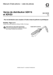
Instructions-Parts List
SDV15 and XDV20 Dispense Valve
312789E
- For non-metered dispensing of petroleum and synthetic-based oil Models: Pages 2 and 3
1500 psi (10 MPa, 103.4 bar) Maximum Working Pressure
Important Safety Instructions
SDV15 Model Shown
Read all warnings and instructions in this
manual. Save these instructions.
TI1466a
ENG
Models
Models
SDV15 Dispense Valve Models
All models include: 1/2 npt(f) swivel with locking-open trigger
Part No.
Extension
Nozzles
Fluid Type
247712
247713
247714
247715
247716
247717
Rigid
Flexible
Gear Lube
Rigid
Flexible
NONE
Automatic non-drip, quick close
Automatic non-drip, quick close
Automatic, non-drip, quick close
Automatic, non-drip, quick close
Automatic, non-drip, quick close
NONE
Oil
Oil
Gear Lube
Anti-freeze
Anti-freeze
All
All models include: 1/2 - 14 BSPP swivel with locking-open trigger
Part No.
Extension
Nozzles
Fluid Type
24H384
24H385
24H386
24H387
24H388
24H389
Rigid
Flexible
Gear Lube
Rigid
Flexible
NONE
Automatic non-drip, quick close
Automatic non-drip, quick close
Automatic, non-drip, quick close
Automatic, non-drip, quick close
Automatic, non-drip, quick close
NONE
Oil
Oil
Gear Lube
Anti-freeze
Anti-freeze
All
All models include: 1/2 - 14 BSPT swivel with locking-open trigger
2
Part No.
Extension
Nozzles
Fluid Type
24H390
24H391
24H392
24H393
24H394
24H395
Rigid
Flexible
Gear Lube
Rigid
Flexible
NONE
Automatic non-drip, quick close
Automatic non-drip, quick close
Automatic, non-drip, quick close
Automatic, non-drip, quick close
Automatic, non-drip, quick close
NONE
Oil
Oil
Gear Lube
Anti-freeze
Anti-freeze
All
312789E
Models
XDV20 Non-metered Valve Models
NPT Models - All models include locking-open and closed trigger
Part No.
Swivel
Extension
Nozzles
Fluid Type
247718
247721
247722
247723
247724
247725
1/2” npt (f)
1/2” npt (f)
3/4“ npt (f)
3/4” npt (f)
1/2” npt (f)
3/4” npt (f)
Rigid
Flexible
Rigid
Flexible
NONE
NONE
High flow, non-drip, quick close
High flow, non-drip, quick-close
High flow, non-drip, quck close
High flow, non-drip, quick close
NONE
NONE
Oil / Anti-freeze
Oil / Anti-freeze
Oil / Anti-freeze
Oil / Anti-freeze
Oil / Anti-freeze
Oil / Anti-freeze
BSPP Models - All models include locking-open and closed trigger
Part No.
Swivel
Extension
Nozzles
Fluid Type
24H407
24H408
24H409
24H410
24H411
24H412
1/2” - 14 BSPP
1/2” - 14 BSPP
3/4“- 14 BSPP
3/4” - 14 BSPP
1/2” - 14 BSPP
3/4” - 14 BSPP
Rigid
Flexible
Rigid
Flexible
NONE
NONE
High flow, non-drip, quick close
High flow, non-drip, quick-close
High flow, non-drip, quck close
High flow, non-drip, quick close
NONE
NONE
Oil / Anti-freeze
Oil / Anti-freeze
Oil / Anti-freeze
Oil / Anti-freeze
Oil / Anti-freeze
Oil / Anti-freeze
BSPT Models - All models include locking-open and closed trigger
Part No.
Swivel
Extension
Nozzles
Fluid Type
24H413
24H414
24H415
24H416
24H417
24H418
1/2” - 14 BSPT
1/2” - 14 BSPT
3/4“ - 14 BSPT
3/4” - 14 BSPT
1/2”- 14 BSPT
3/4” - 14 BSPT
Rigid
Flexible
Rigid
Flexible
NONE
NONE
High flow, non-drip, quick close
High flow, non-drip, quick-close
High flow, non-drip, quck close
High flow, non-drip, quick close
NONE
NONE
Oil / Anti-freeze
Oil / Anti-freeze
Oil / Anti-freeze
Oil / Anti-freeze
Oil / Anti-freeze
Oil / Anti-freeze
312789E
3
Warnings
Warnings
The following warnings are for the setup, use, grounding, maintenance, and repair of this equipment. The exclamation point symbol alerts you to a general warning and the hazard symbol refers to procedure-specific risk. Refer back
to these warnings. Additional, product-specific warnings may be found throughout the body of this manual where
applicable.
WARNING
FIRE AND EXPLOSION HAZARD
When flammable fluids are present in the work area, such as gasoline and windshield wiper fluid, be
aware that flammable fumes can ignite or explode. To help prevent fire and explosion:
• Use equipment only in well ventilated area.
• Eliminate all ignition sources, such as cigarettes and portable electric lamps.
• Keep work area free of debris, including rags and spilled or open containers of solvent and gasoline.
• Do not plug or unplug power cords or turn lights on or off when flammable fumes are present.
• Ground all equipment in the work area.
• Use only grounded hoses.
• If there is static sparking or you feel a shock, stop operation immediately. Do not use equipment
until you identify and correct the problem.
• Keep a working fire extinguisher in the work area.
EQUIPMENT MISUSE HAZARD
Misuse can cause death or serious injury.
• Do not operate the unit when fatigued or under the influence of drugs or alcohol.
• Do not exceed the maximum working pressure or temperature rating of the lowest rated system
component. See Technical Data in all equipment manuals.
• Use fluids and solvents that are compatible with equipment wetted parts. See Technical Data in all
equipment manuals. Read fluid and solvent manufacturer’s warnings. For complete information
about your material, request MSDS forms from distributor or retailer.
• Check equipment daily. Repair or replace worn or damaged parts immediately with genuine manufacturer’s replacement parts only.
• Do not alter or modify equipment.
• Use equipment only for its intended purpose. Call your distributor for information.
• Route hoses and cables away from traffic areas, sharp edges, moving parts, and hot surfaces.
• Do not kink or over bend hoses or use hoses to pull equipment.
• Keep children and animals away from work area.
• Comply with all applicable safety regulations.
SKIN INJECTION HAZARD
High-pressure fluid from dispense valve, hose leaks, or ruptured components will pierce skin. This may
look like just a cut, but it is a serious injury that can result in amputation. Get immediate surgical
treatment.
• Do not point dispense valve at anyone or at any part of the body.
• Do not put your hand over the end of the dispense nozzle.
• Do not stop or deflect leaks with your hand, body, glove, or rag.
• Follow Pressure Relief Procedure in this manual, when you stop spraying and before cleaning,
checking, or servicing equipment.
4
312789E
Installation
Installation
Grounding
Pressure Relief Procedure
NOTICE
Do not use PTFE tape on pipe joints; it may cause a
loss of ground across the pipe joint.
The equipment must be grounded. Grounding reduces
the risk of static and electric shock by providing an
escape wire for the electrical current due to static build
up or in the event of a short circuit.
Pump: follow manufacturer’s recommendations.
Air and fluid hoses: use only grounded hoses.
Air compressor: follow manufacturer’s recommendations.
Fluid supply container: follow local code.
To maintain grounding continuity when flushing or relieving pressure, always hold metal part of valve firmly to
side of grounded metal pail, then trigger valve.
The equipment stays pressurized until pressure is
manually relieved. To reduce the risk of serious injury
from pressurized fluid, accidental spray from the dispense valve or splashing fluid, follow this Pressure
Relief procedure whenever you:
•
•
•
Are instructed to relieve pressure
Check, clean or service any system component
Install or clean fluid nozzles
1. Turn off power supply to pump.
2. Trigger valve into waste container to relieve pressure.
3. Open any bleeder-type air valves and fluid drain
valves in the system.
4. Leave drain valve open until you are ready to pressurize the system.
If you suspect the spray tip or hose is clogged or that
pressure has not been fully relieved after following the
steps above, VERY SLOWLY loosen tip guard retaining
nut or hose end coupling to relieve pressure gradually,
then loosen completely. Clear hose or tip obstruction.
Pre-Installation Procedure
1. Relieve pressure as described in Pressure Relief
Procedure.
2. Close fluid shut-off valve (A, FIG. 1).
3. Ground hose, reel and console (See Grounding).
312789E
5
Installation
Typical Installation
Installation Procedure
FIG. 1 shows a typical installation. The installation is only
a guide. The components shown are typical; however, it
is not a complete system design. Contact your Graco
distributor for assistance in designing a system to suit
your particular needs.
NOTICE
If this is a new installation, or if the lines are contaminated, flush the lines before you install dispensing
valve.
Dispense valves can also be installed on a console.
NOTICE
•
•
Do not use this dispense valve on non-Graco consoles. Such use could result in trigger becoming
inadvertently pressed while valve is stowed.
1. Relieve pressure, page 5.
To prevent line contamination, which can cause
equipment damage or malfunction, flush the lines
before your install the equipment in the system.
2. Close fluid shut-off valve (A) at each dispense position.
Steps 2 - 6 are the Flushing Procedure.
3. Make sure main fluid outlet valve at pump is closed,
the air pressure to the pump motor is adjusted, and
the air valve is open. Slowly open main fluid valve.
4. Place hose end (with no dispense valve connected)
into a container of waste oil. Secure hose in container so it will not come out during flushing. If you
have multiple dispense positions, flush the dispense
position farthest from pump first and work your way
toward the pump.
C
A
D
5. Slowly open fluid shut off valve (A) at dispense position. Flush out a sufficient amount of oil to ensure
the entire system is clean. Close valve.
6. Repeat Step 5 for all dispense positions.
B
E
ti11468_3
FIG. 1
6
Key
Description
A
Fluid shutoff valve
B
Hose
C
Hose reel fluid inlet hose
D
Hose reel
E
Dispense valve
A Thermal Relief Kit (not shown) is required.The Kit
required will vary by pump selected. See Parts, page
16 for a list of available kits.
312789E
Operation
Existing Installation
4. Apply thread sealant to male threads of hose fitting.
Thread hose fitting into swivel (6). Tighten firmly.
5. Thread nozzle (12) or nozzle adapter onto extension
and tighten firmly.
1. Relieve pressure, page 5.
2. Loosen and disconnect hose from old dispense
valve (the one you are replacing).
6. Open all dispense position shut-off valves. Start
pump to pressurize system.
11a
Existing or New Installation
1
For Steps 3 - 5 see FIG. 2.
3. Thread extension (11) into outlet of the dispense
valve handle (1). Tighten securely.
12
6
11
NOTICE
•
Do not overtighten extension.
•
Thread extension in at least three full turns. Position
extension for proper alignment with valve handle (1)
and tighten nut (11a).
ti11466a
FIG. 2
Operation
For part numbers referenced in these instructions, see
Parts, page 10.
Dispensing Procedure
1. Open (or unlock) nozzle.
2. Pull trigger (15) toward the valve handle (1) to open
valve and begin dispensing.
To reduce the risk of a serious bodily injury, including
fluid injection, never exceed the maximum working
pressure of the valve you are using or of the lowest
rated component in your system.
3. Lock valve open by keeping trigger (15) squeezed
and depressing trigger lock button (14). Then you
can release trigger.
4. To release trigger lock (14), pull trigger (15) toward
valve handle (1).
The XDV20 dispense valve trigger automatically
locks whenever you release the trigger and must be
unlocked each time you begin a new dispense.
312789E
5. Release trigger (15) to stop dispensing.
6. Close (lock) nozzle.
7
Troubleshooting
Troubleshooting
Relieve pressure before you check or repair dispense
valve. Be sure all other valves and controls and the
pump are operating properly.
Problem
Slow or no fluid flow
Cause
Screen is clogged
Pump pressure is low
Shutoff valve is not full open
Solution
1. Relieve pressure.
2. Clean or replace strainer (4a)
and washer 4b. Order Filter Kit
256164.
3. If the problem remains, contact
your Graco distributor for repair
or replacement.
Oil leaks from swivel
Swivel is loose
Torque the swivel (6) to 7-10 ft-lb
(9-13 N.m).
If the problem remains, contact your
Graco distributor for repair or
replacement.
O-ring is worn or damaged
Replace swivel (6). Torque swivel to
7-10 ft-lb (9-13 N.m).
If the problem remains, contact your
Graco distributor for repair or
replacement.
Oil drips from nozzle*
Nozzle is damaged or obstructed
Inspect nozzle for damage or
obstructions. Replace if damaged.
Valve leaks
O-rings or valve seat are worn or
damaged
Replace seals (9) and/or valve seat
(2).
*Some fluid seepage is possible in applications where thermal expansion of fluid is possible.
8
312789E
Service
Service
Valve Handle Repair
The large end of the push rod (3) fits into a notch in
the cam (8) which is part of the trigger assembly. It
is important you know this before you remove or
install parts.
8. Lubricate the cam (8) and slide it into the valve handle (1), making sure the notch is oriented as shown
in FIG. 3, with the large end of the push rod (3) resting in the notch of the cam.
9. Replace the screws (7) and seals (9). Torque
screws to 15 -25 in-lb (1.7 to 2.8 N•m).
10. Replace swivel (6). Torque to 7-10 ft-lb (31 to 44
N•m).
Filter Replacement
Order Filter Kit 256164.
1. Relieve pressure, page 5.
2. If you are replacing the seals (9), the cam (8) or the
push rod (3), remove the swivel (6) and remove the
internal pieces. You must remove the cam in
order to get the push rod out of the valve end.
3. Remove screws (7) and washers (10) and remove
trigger (15).
4. Push cam (8) out of valve handle (1).
1. Relieve pressure, page 5.
2. Unscrew hose fitting from swivel (6).
3. Remove swivel (6) from valve handle (1).
5. Replace seals (9) and/or cam (8).
6. Replace any worn or broken parts.
4. Remove strainer (4a) and washer (4b) from inside of
swivel (6).
7. Reassembly internal parts. Refer to FIG. 3 for correct installation order and orientation of parts.
5. Replace washer (4b) and strainer (4a). Refer to FIG.
4 to ensure correct orientation of filter in swivel.
The push rod (3) must be inserted through the outlet end of the valve handle before cam (8) is
installed.
1
4b
4a
7
10
6
3
8
1
10
ti12074a
7
FIG. 4
9
6. Thread hose fitting into swivel (6) and tighten.
Torque swivel to 7-10 ft-lb (31- 44 N•m).
15
6
ti12073a
FIG. 3
312789E
9
Parts
Parts
SDV15 Dispense Valves
0
FN
1
2
3
4
4a
4b
6
Part No.
15R709
191313
277673
256164
238399
24H382
24H383
110637
191315
113574
191552
7
8
9
10
Description
HANDLE, valve, standard duty
SEAT, valve
ROD, push
KIT, filter, includes 4a and 4b
STRAINER
WASHER, plain
SWIVEL, straight, NPT
SWIVEL, straight, BSPP
SWIVEL, straight, BSPT
SCREW, machine, pan head
CAM
SEAL, quad ring
WASHER, flat
FN
11*
12*
13
14
15
16
18
20†
22
25†
Qty
1
1
1
1
10
10
1
1
1
2
1
2
2
Part No. Description
113924
15R526
191320
192106
113493
172479
15K672
290180
Qty
1
KIT, nozzle and extension, page 12
1
SPRING, compression
1
LOCK, trigger
1
TRIGGER
1
GUIDE, spring
1
SPRING, compression
1
TAG, warning
1
ADAPTER, o-ring, model 247714
1
TAG, caution
1
*These parts are not included on model 247717
† Not shown
11
12
1
Torque to 7-10 ft. lbs (9-13 N•m)
2
Torque to 15 - 25 in. lbs (1.7- 2.8 N•m)
11
2
7
10
12
3
1
18
12
9
10
2
11
72
4b
4a
6
16
13
8
22
14
1
ti11467b
15
10
312789E
Parts
Parts
XDV20 Non-metered Valves
FN
1
2
3
4
4a
4b
6
Part No.
15M660
15U704
277673
256164
247344
24H097
24H098
247345
24H099
24H100
7
8
110637
191315
FN
9
10
11*
12*
13
14
15
16
17
18
20
22†
24
25
26†
Description
Qty
HANDLE, valve, medium duty
1
SEAT, valve
1
ROD, push
1
KIT, filter, includes 4a and 4b
1
STRAINER
10
WASHER, plain
10
SWIVEL, straight, 1/2 NPT models
1
247718, 247721, 247724
SWIVEL, straight, 1/2 BSPT, mod1
els 24H413, 24H414, 24H417
SWIVEL, straight, 1/2 BSPP, models 24H407, 24H408, 24H411
SWIVEL, straight, 3/4 NPT models
247722, 247723, 247725
SWIVEL, straight, 3/4 BSPT, mod1
els 24H415, 24H416, 24H418
SWIVEL, straight, 3/4 BSPP, models 24H409, 24H410, 24H412
SCREW, machine, pan head
2
CAM
1
Part No. Description
113574 SEAL, quad ring
191552 WASHER, flat
114680
15R016
15M886
15R015
15R014
15R013
113493
172479
15U700
15U701
290180
Qty
2
2
1
KIT, nozzle and extension, page 12
1
PIN, dowel
1
LATCH, pin
1
TRIGGER
1
LATCH, arm
1
LATCH, spring
1
LATCH, lever
1
SPRING, compression
1
TAG, warning
1
PLUNGER, trigger, lift
1
SPRING, secondary
1
TAG, caution
1
* These parts are not included on models 247724 or
247725
† Not shown
11
1
Torque to 7-10 ft. lbs (9-13 N•m)
2
Torque to 15- 25 in. lbs (1.7- 2.8 N•m)
11
2
7
3
12
10
1
9
8
24
2
2
16
17
4b
1
10
7
20
6
9
25
4a
13
18
14
15
6
312789E
1
ti12076a
11
Parts
SDV15 Nozzle Extension Kits
Part No.
Description
Fluid Type
*illustration note
255852*
Automatic, non-drip quick close nozzle with
rigid extension.
Oil
ti11827
ti11826
255853*
Automatic, non-drip quick close nozzle with
flexible extension
Oil
ti11827
ti11825
255854
Non-drip, quick close nozzle with rigid extension
ti11830
Gear Lube
ti11831
ti12078a
*Used for dispensing 5gpm (22.7 lpm) or less.
continued
12
312789E
Parts
Part No.
Description
Fluid Type
*illustration note
255855*
Non-drip, quick close nozzle with rigid extension
ti11828
Anti-freeze
ti11826
255856*
Non-drip, quick close nozzle with flexible
extension
Anti-freeze
ti11828
ti11825
255857
Non-drip, quick close, high-flow nozzle with
rigid extension
Oil and
Anti-freeze
ti11829
ti11826
255858
Non-drip, quick close, high flow nozzle with
flexible extension
Oil and
Anti-freeze
ti11829
ti11825
*Used for dispensing 5gpm (22.7 lpm) or less.
312789E
13
Parts
SDV15 Nozzle Kits
Part No.
Description
255459*
Automatic, non-drip, quick-close nozzle
255460*
255461
• BODY, nozzle
1
• O-RING, packing
1
• SPRING, compression
1
• O-RING, packing
1
• STEM, nozzle, valve
1
• SEAT, valve
1
Fluid Type
Oil
Automatic, non-drip, quick-close nozzle
• BODY, nozzle
1
• SPRING, compression
1
• O-RING, packing
1
• STEM, nozzle, valve,
1
• O-RING, packing
1
• SEAT, valve
1
Anti-freeze
Automatic, non-drip, high-flow nozzle
a
• STEM, nozzle, qty 1
b
• BODY, nozzle, qty 1
c
• O-RING, packing, qty1
d
• O-RING, packing, qty 1
e
• O-RING, packing, qty 1
255470
Qty
Oil and Antifreeze
Non-drip, quick-close
nozzle
• Housing
1
• Body, nozzle
1
• O-RING, packing
1
• O-RING, packing,
1
• Plug, Hollow, hex
1
Gear Lube
*Used for dispensing 5gpm (22.7 lpm) or less.
14
312789E
Parts
XDV20 Nozzle Extension Kits
Part No.
Description
Fluid Type
*illustration note
255921
Non-drip quick close,high flow nozzle with
rigid extension.
Oil and
Anti-freeze
ti12680a
255859
Non-drip quick close, high flow nozzle with
flexible extension.
Oil and
Anti-freeze
ti12679a
XDV20 Nozzle Kits
Part No.
Description
255793
Non-drip, quick close, high
flow nozzle
312789E
Qty
• O-RING, packing
1
• O-RING, packing
1
• BODY, nozzle, high flow
1
• O-RING, packing
1
• STEM, nozzle, heavy duty
1
Fluid Type
Oil and
Anti-freeze
15
Technical Data
Thermal Relief Kits
Part No.
112353
235998
237601
237893
248296
238899
240429
248324
Description
Diaphragm pump for fuel dispense, valve only
Mini Fire-Ball™ 225, 3:1
Fire-Ball 425, 3:1
Fire-Ball 300, 5:1 and Fire-Ball 425, 6:1
Fire-Ball 300, 5:1 and Fire-Ball 425, 6:1
(same as 237893 minus bung adapter and
swivel. Includes 6-foot hose)
Diaphragm pump
Fire-Ball 425, 10:1
Fire-Ball 425, 10:1 (same as 240429 minus bung
adapter and swivel. Includes 6-foot hose)
PSI (bar) Rating
50 psi (3.4 bar)
600 psi (41 bar)
600 psi (41 bar)
900 psi (62 bar)
900 psi (62 bar)
150 psi (10.4 bar)
1600 psi (110 bar)
1600 psi (110 bar)
Technical Data
Maximum Flow Range
SDV15
XDV20
Maximum Working Pressure SDV15/XDV20
SDV15/XDV20 Weight
Inlet
Outlet
SDV15
XDV20
Operating temperature range
Wetted parts
Fluid compatibility
16
15 gpm (56.8 lpm)
20 gpm (75 lpm)
1500 psi (102 bar)
0.4 lbs (0.18 kg)
See pages 2 and 3 for models and configuration information
3/4 - 16 straight thread o-ring boss
7/8 - 14 straight thread o-ring
-40°F to 180°F (-40°C to 82°C)
Aluminum, Stainless Steel, CS, Acetal, Nitrile Rubber, TPE
Antifreeze, gear lube, oil
312789E
Notes
Notes
312789E
17
Graco Standard Warranty
Graco warrants all equipment referenced in this document which is manufactured by Graco and bearing its name to be free from defects in
material and workmanship on the date of sale to the original purchaser for use. With the exception of any special, extended, or limited warranty
published by Graco, Graco will, for a period of five years from the date of sale, repair or replace any part of the equipment determined by Graco to
be defective. This warranty applies only when the equipment is installed, operated and maintained in accordance with Graco’s written
recommendations.
This warranty does not cover, and Graco shall not be liable for general wear and tear, or any malfunction, damage or wear caused by faulty
installation, misapplication, abrasion, corrosion, inadequate or improper maintenance, negligence, accident, tampering, or substitution of
non-Graco component parts. Nor shall Graco be liable for malfunction, damage or wear caused by the incompatibility of Graco equipment with
structures, accessories, equipment or materials not supplied by Graco, or the improper design, manufacture, installation, operation or
maintenance of structures, accessories, equipment or materials not supplied by Graco.
This warranty is conditioned upon the prepaid return of the equipment claimed to be defective to an authorized Graco distributor for verification of
the claimed defect. If the claimed defect is verified, Graco will repair or replace free of charge any defective parts. The equipment will be returned
to the original purchaser transportation prepaid. If inspection of the equipment does not disclose any defect in material or workmanship, repairs will
be made at a reasonable charge, which charges may include the costs of parts, labor, and transportation.
THIS WARRANTY IS EXCLUSIVE, AND IS IN LIEU OF ANY OTHER WARRANTIES, EXPRESS OR IMPLIED, INCLUDING BUT NOT LIMITED
TO WARRANTY OF MERCHANTABILITY OR WARRANTY OF FITNESS FOR A PARTICULAR PURPOSE.
Graco’s sole obligation and buyer’s sole remedy for any breach of warranty shall be as set forth above. The buyer agrees that no other remedy
(including, but not limited to, incidental or consequential damages for lost profits, lost sales, injury to person or property, or any other incidental or
consequential loss) shall be available. Any action for breach of warranty must be brought within two (2) years of the date of sale.
GRACO MAKES NO WARRANTY, AND DISCLAIMS ALL IMPLIED WARRANTIES OF MERCHANTABILITY AND FITNESS FOR A
PARTICULAR PURPOSE, IN CONNECTION WITH ACCESSORIES, EQUIPMENT, MATERIALS OR COMPONENTS SOLD BUT NOT
MANUFACTURED BY GRACO. These items sold, but not manufactured by Graco (such as electric motors, switches, hose, etc.), are subject to
the warranty, if any, of their manufacturer. Graco will provide purchaser with reasonable assistance in making any claim for breach of these
warranties.
In no event will Graco be liable for indirect, incidental, special or consequential damages resulting from Graco supplying equipment hereunder, or
the furnishing, performance, or use of any products or other goods sold hereto, whether due to a breach of contract, breach of warranty, the
negligence of Graco, or otherwise.
FOR GRACO CANADA CUSTOMERS
The Parties acknowledge that they have required that the present document, as well as all documents, notices and legal proceedings entered into,
given or instituted pursuant hereto or relating directly or indirectly hereto, be drawn up in English. Les parties reconnaissent avoir convenu que la
rédaction du présente document sera en Anglais, ainsi que tous documents, avis et procédures judiciaires exécutés, donnés ou intentés, à la suite
de ou en rapport, directement ou indirectement, avec les procédures concernées.
Graco Information
TO PLACE AN ORDER, contact your Graco distributor or call to identify the nearest distributor.
Phone: 612-623-6928 or Toll Free: 1-800-533-9655, Fax: 612-378-3590
All written and visual data contained in this document reflects the latest product information available at the time of publication.
Graco reserves the right to make changes at any time without notice.
Original instructions. This manual contains English. MM 312789
Graco Headquarters: Minneapolis
International Offices: Belgium, China, Japan, Korea
GRACO INC. P.O. BOX 1441 MINNEAPOLIS, MN 55440-1441
Copyright 2008, Graco Inc. is registered to I.S. EN ISO 9001
www.graco.com
5/2008, Revised 1/2011