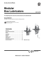
1
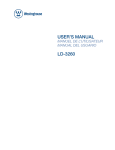
Instructions/Parts
Modular
Box Lubricators
312147B
For dispensing non-corrosive and non-abrasive oils and lubricants.
Model MBXXXX
See page 4 for model numbers and maximum working pressures.
Important Safety Instructions
Read all warnings and instructions in this manual.
Save these instructions.
Contents
Warnings . . . . . . . . . . . . . . . . . . . . . . . . . . . . . . . . . 2
Pressure Relief Procedure . . . . . . . . . . . . . . . . . . . 3
Models . . . . . . . . . . . . . . . . . . . . . . . . . . . . . . . . . . . 4
Installation . . . . . . . . . . . . . . . . . . . . . . . . . . . . . . . . 5
Operation . . . . . . . . . . . . . . . . . . . . . . . . . . . . . . . . . 6
Service . . . . . . . . . . . . . . . . . . . . . . . . . . . . . . . . . . . 7
Technical Data . . . . . . . . . . . . . . . . . . . . . . . . . . . . . 8
Dimensions . . . . . . . . . . . . . . . . . . . . . . . . . . . . . . . 9
Graco Standard Warranty . . . . . . . . . . . . . . . . . . . 10
Graco Information . . . . . . . . . . . . . . . . . . . . . . . . . 10
ti9848a
Model 88 Pumps
II 2 G c T4
Warnings
Warnings
The following warnings are for the setup, use, grounding, maintenance, and repair of this equipment. The exclamation point symbol alerts you to a general warning and the hazard symbol refers to procedure-specific risk. Refer back
to these warnings. Additional, product-specific warnings may be found throughout the body of this manual where
applicable.
WARNING
SKIN INJECTION HAZARD
High-pressure fluid from dispense valve, hose leaks, or ruptured components will pierce skin. This may
look like just a cut, but it is a serious injury that can result in amputation. Get immediate surgical
treatment.
• Do not point dispense valve at anyone or at any part of the body.
• Do not put your hand over the end of the dispense nozzle.
• Do not stop or deflect leaks with your hand, body, glove, or rag.
• Follow Pressure Relief Procedure in this manual, when you stop spraying and before cleaning,
checking, or servicing equipment.
FIRE AND EXPLOSION HAZARD
When flammable fluids are present in the work area, such as gasoline and windshield wiper fluid, be
aware that flammable fumes can ignite or explode. To help prevent fire and explosion:
• Use equipment only in well ventilated area.
• Eliminate all ignition sources, such as cigarettes and portable electric lamps.
• Keep work area free of debris, including rags and spilled or open containers of solvent and gasoline.
• Do not plug or unplug power cords or turn lights on or off when flammable fumes are present.
• Ground all equipment in the work area.
• Use only grounded hoses.
• If there is static sparking or you feel a shock, stop operation immediately. Do not use equipment
until you identify and correct the problem.
• Keep a working fire extinguisher in the work area.
EQUIPMENT MISUSE HAZARD
Misuse can cause death or serious injury.
• Do not operate the unit when fatigued or under the influence of drugs or alcohol.
• Do not exceed the maximum working pressure or temperature rating of the lowest rated system
component. See Technical Data in all equipment manuals.
• Use fluids and solvents that are compatible with equipment wetted parts. See Technical Data in all
equipment manuals. Read fluid and solvent manufacturer’s warnings. For complete information
about your material, request MSDS forms from distributor or retailer.
• Check equipment daily. Repair or replace worn or damaged parts immediately with genuine manufacturer’s replacement parts only.
• Do not alter or modify equipment.
• Use equipment only for its intended purpose. Call your distributor for information.
• Route hoses and cables away from traffic areas, sharp edges, moving parts, and hot surfaces.
• Do not kink or over bend hoses or use hoses to pull equipment.
• Keep children and animals away from work area.
• Comply with all applicable safety regulations.
2
312147B
Pressure Relief Procedure
WARNING
MOVING PARTS HAZARD
Moving parts can pinch or amputate fingers and other body parts.
• Keep clear of moving parts.
• Do not operate equipment with protective guards or covers removed.
• Pressurized equipment can start without warning. Before checking, moving, or servicing equipment,
follow the Pressure Relief Procedure in this manual. Disconnect power or air supply.
PRESSURIZED ALUMINUM PARTS HAZARD
Do not use 1,1,1-trichloroethane, methylene chloride, other halogenated hydrocarbon solvents or fluids
containing such solvents in pressurized aluminum equipment. Such use can cause serious chemical
reaction and equipment rupture, and result in death, serious injury, and property damage.
PERSONAL PROTECTIVE EQUIPMENT
You must wear appropriate protective equipment when operating, servicing, or when in the operating
area of the equipment to help protect you from serious injury, including eye injury, inhalation of toxic
fumes, burns, and hearing loss. This equipment includes but is not limited to:
• Protective eyewear
• Clothing and respirator as recommended by the fluid and solvent manufacturer
• Gloves
• Hearing protection
Pressure Relief Procedure
Fluid under high pressure can be injected through the
skin and cause serious injury. To reduce the risk of an
injuiry from injection, splashing fluid, or moving parts,
follow the Pressure Relief Procedure whenever you:
•
are instructed to relieve the pressure,
•
check, clean, or service any system equipment,
•
or install or clean fluid nozzle.
1. Turn off the power supply to the pump.
2. Open any fluid drain valves in the system.
3. Leave the drain valve open until you are ready to
pressurize the system.
If you suspect that pressure is not fully relieved
after following the previous steps, using a rag very
slowly loosen the hose end coupling or a fitting on
the fluid line and allow pressure to be relieved gradually, then loosen the part completely and clear the
clog.
312147B
3
Models
Models
ti9849a
Model 88 Pumps
ti9848a
Part Number
Standard
Pump
Pressurized
Pump
Option
562953
562955
562957
562954
562956
562958
562961
562963
562965
562962
562964
562966
4
76B
76C
76E
88B
88C
88E
Model 76 Pumps
Drops
Cu. In.
per stroke per stroke
Piston
Size
(in.)
Maximum pressure
3/16
1/4
3/8
3/16
1/4
3/8
7500 psi (52.5 MPa, 525 bar)
6000 psi (42.5 MPa, 425 bar)
2500 psi (17.5 MPa, 175 bar)
7500 psi (52.5 MPa, 525 bar)
6000 psi (42.5 MPa, 425 bar)
2500 psi (17.5 MPa, 175 bar)
Cm3
per stroke
Strokes
per
minute
Max. Min. Max. Min. Max. Min. Max. Min.
6
12
27
6
12
27
1
2
4
1
2
4
0.013
0.024
0.055
0.013
0.024
0.055
0.002
0.004
0.008
0.002
0.004
0.008
0.213
0.393
0.901
0.213
0.393
0.901
0.033
0.066
0.131
0.033
0.066
0.131
50
50
50
50
50
50
3
3
3
3
3
3
312147B
Installation
Installation
System Connections
CAUTION
The installation and all work concerning assembly,
maintenance, and repair must be completed by qualified personnel.
Mounting
When possible, mount the lubricator on a surface
that experiences little to no vibration.
Reservoirs have end mounting lugs as shown in outline
drawings on page 9. Use all mount features provided to
ensure the lubricator is rigidly fixed after installation.
Select a mounting location that will accomplish the following goals:
•
•
•
It is recommended that each pumping unit be installed
with a check valve in the discharge line so that the pump
assembly may be removed from the reservoir without
loss of lubricant in the discharge lines. The installation of
a second check valve at the end of the discharge line
will prevent line drainage and act as a positive means of
avoiding feedback of system pressure to pump.
When using Model 88 pumps, torque the union fitting on
the outlet check valve to 37- 42 ft-lb (50-57 N•m)
Lubricant Types and Viscosities
Graco Modular Box Lubricators are suitable for use with
mineral oil or synthetic base lubricants with viscosities in
the range of 100 to 5000 SUS under pumping conditions.
Allow easy access to the lubricator for filling the
reservoir and periodic maintenance.
Provide a stable surface upon which the lubricator can operate.
The lubricator must be connected to a ground
source.
Drive Mechanism
A 5/8 in. diameter shaft is provided to connect the lubricator to a rotary power source. A number 5 woodruff key
and key way on the shaft are provided to aid in connecting this source.
Install protective guards around all drive components
upon installation.
CAUTION
The recommended speed of the mechanism driving
the lubricator is 3 - 50 rpm. Do not exceed the maximum value of 50 rpm to avoid pump damage.
312147B
5
Operation
Operation
1. Loosen the adjustment rod lock nut.
Oil Level
2. Turn the adjustment rod guide clockwise to
decrease the amount of lubricant dispensed, or
counterclockwise to increase the amount of lubricant dispensed.
When necessary, completely fill the lubricator reservoir
with clean filtered lubricant. A sight level gauge is provided on the reservoir to monitor the fluid level. Oil level
should not be allowed to drop below the line indicating
an empty reservoir.
3. Once the desired settings have been achieved,
tighten the adjustment rod lock nut by hand.
.
During the initial filling, remove the vent plug from
pumps using sight glasses prior to filling the reservoir.
This allows lubricant to rise in the vacuum tube up to the
level of lubricant in the reservoir and reduces the priming required at start up.
The vacuum tube dispense rate is accurate after
the pump has operated long enough to stabilize
the pressure inside the sight glass. There is a time
lag at start-up, low dispense rates, and during the
adjustment of dispense rates. Allow sufficient time
to ensure the proper amount of lubricant is dispensed.
If pressurized pumps are used, the reservoir should
be filled with lubricant to extend the life of the internally moving components.
Pump Priming
If the sight well on the pump does not contain oil, the
pump should be primed using the following procedure:
1. If using a vacuum type pump with a sight glass,
remove the vent screw located on the top of the
sight glass.
2. Adjust the pump stroke length to its maximum setting.
3. Depress the hand plunger assembly and release
when the cap contacts the adjustment rod guide.
4. Repeat until an air free stream of fluid exits the
pump outlet.
5. Replace the vent screw at the top of the sight glass.
Pumping Rate
The amount of lubricant dispensed from each pump can
be adjusted. The volume dispensed by each pump is
indicated by the amount of lubricant dripping from the
vacuum tube inside the sight glass.
The amount of dispensed volume can be adjusted by
performing the following steps:
6
312147B
Service
Service
seating, or a defective o-ring. Repair as
required.
b.
CAUTION
The installation and all work concerning assembly,
maintenance, and repair must be completed by qualified personnel.
1. Follow the Pressure Relief Procedure on page 3.
2. Lubricator operation can be checked by observing
the drip tube. If the correct pumping rate is maintained, no servicing is required other than periodic
replenishment of the reservoir. If the sight glass well
pumps dry or no flow is observed, check the following points until the cause is determined and corrected.
a. Check the vent plug for proper sealing. Any
nicks or cracks will cause an air leak into the
sight glass.
b.
Check shaft rotation. If the lubricator shaft is not
rotating, determine the cause and repair as necessary.
c.
Check oil level and viscosity. Be sure the reservoir is filled with oil.
d. Check pump priming. If necessary, prime the
pump in accordance with the “Operating
Instructions”.
e. Check the feed adjustment and readjust if the
pumping rate is too low.
f.
Check the actuating linkage for proper operation. If defective, isolate the broken part and
repair or replace as required.
3. If none of the above steps isolate the malfunction,
the cause is in the pump assembly. The following
items should be checked before removing the pump
assembly from the cover.
a. Check the sight for inward leakage due to a
crack in the sight glass, improper sight glass
312147B
Check for an obstruction in the drip tube and
remove if found.
4. If these steps do not isolate the malfunction, disconnect the discharge tubing and remove the pump
assembly which is attached to the cover with two
screws. It is not necessary to stop the equipment on
which the lubricator is installed or to empty the reservoir. A spare pump should be on hand for use during emergencies when a pump is being repaired.
5. If the sight glass fills with lubricant proceed as follows:
a. Remove the vent plug and allow the lubricant to
pump down to the proper level. Replace the
vent plug. The pump should operate normally.
b.
If the sight glass continues to fill with lubricant
check all terminal check valves for proper operation. If the valves are operating properly,
remove and clean the pump assembly, then
reinstall the pump in the system and check
operation.
6. If the sight glass still fills with lubricant it may be
caused by temperature variation.
a. When the unit is not operating, remove the vent
plug and allow the lubricant to pump down to
the proper level. Replace the vent plug. The
pump will now function properly. The sight glass
may fill with fluid without affecting the operation
of the lubricator as long as the drip tube
remains above the lubricant level to show the
rate of pumping.
b.
When the unit is operating, the sight level will
vary depending on temperature variations. If the
level falls to less than 1/4 inch above sight glass
flange, add lubricant to the proper level (3/8 inch
below the discharge of the drip tube) through
the vent hole. If the level is too high, remove the
vent plug and allow the unit to pump down
before replacing the vent plug.
7
Technical Data
Other servicing that may be required is listed below:
•
Periodic cleaning of the lubricator is desirable to
eliminate contamination that may have occurred in
the oil. To accomplish this, remove all pumping units
and clean the pumps and reservoir by brushing
loose all foreign matter, dipping in solvent and blowing dry with compressed air.
•
If external leakage is observed, determine the
cause (loose bolts, defective gaskets, or seals) and
repair as required.
Technical Data
Plunger diameter . . . . . . . . . . . . . . . . . . . . . . . . . . . . . . . 3/16 in. (4.8 mm) for Models 76B and 88B
3/8 in. (9.5 mm) for Models 76E and 88E
1/4 in. (6.4 mm) for Models 76C and 88C
Maximum Working Pressure*. . . . . . . . . . . . . . . . . . . . . . 2500-7500 psi (17.5-52.5 MPa; 175-525 bar)
Minimum Pump Dispensing Rate* . . . . . . . . . . . . . . . . . . 0.002 - 0.008 cu. in.
Maximum Pump Dispensing Rate* . . . . . . . . . . . . . . . . . 0.013 - 0.055 cu. in.
Operating Temperature Range. . . . . . . . . . . . . . . . . . . . . -20°F to 140°F (-29°C to 60°C)
Dispensing Fluid Viscosity . . . . . . . . . . . . . . . . . . . . . . . . 100 - 5000 SUS
Wetted Materials
music wire, carbon steel, nylon, aluminum, nitrile rubber
*Varies with pump selection, see Models chart on page 4.
8
312147B
Dimensions
Dimensions
DIAMETER
FOURMOUNTINGHOLES
"LANKCOVER
ASSEMBLY
490
&ILLCUP
,EVELSIGHT
GAUGE
!
"
NPSF
LUBEOUTLET
(ANDPLUNGERAND
PUMPOUTPUTADJUSTMENT
NPTDRAINPLUG
BOTHSIDES
)NCHES
MILLIMETERS
ti9847
Size
Dimensions - inches (millimeters
Options
Pints
Liters
A
B
T1
4
1.9
5.50 (139.70)
6.75 (171.45)
T2
6
2.8
7.25 (184.15
8.50 (215.90)
T3
8
3.8
10.75 (273.05)
12.00 (304.80)
T4
12
5.7
16.00 (406.40)
17.25 (438.15)
T5
16
7.6
23.00 (584.20
24.25 (615.95)
T6
24
11.3
30.00 (762.00)
31.25 (793.75
T7
32
15.1
37.00 (939.80)
38.25 (971.55)
T8
40
18.9
44.00 (1117.60)
45.25 (1149.35)
Note: A blank cover assembly will be provided for all unused pump stations.
312147B
9
Graco Standard Warranty
Graco warrants all equipment referenced in this document which is manufactured by Graco and bearing its name to be free from defects in
material and workmanship on the date of sale to the original purchaser for use. With the exception of any special, extended, or limited warranty
published by Graco, Graco will, for a period of twelve months from the date of sale, repair or replace any part of the equipment determined by
Graco to be defective. This warranty applies only when the equipment is installed, operated and maintained in accordance with Graco’s written
recommendations.
This warranty does not cover, and Graco shall not be liable for general wear and tear, or any malfunction, damage or wear caused by faulty
installation, misapplication, abrasion, corrosion, inadequate or improper maintenance, negligence, accident, tampering, or substitution of
non-Graco component parts. Nor shall Graco be liable for malfunction, damage or wear caused by the incompatibility of Graco equipment with
structures, accessories, equipment or materials not supplied by Graco, or the improper design, manufacture, installation, operation or
maintenance of structures, accessories, equipment or materials not supplied by Graco.
This warranty is conditioned upon the prepaid return of the equipment claimed to be defective to an authorized Graco distributor for verification of
the claimed defect. If the claimed defect is verified, Graco will repair or replace free of charge any defective parts. The equipment will be returned
to the original purchaser transportation prepaid. If inspection of the equipment does not disclose any defect in material or workmanship, repairs will
be made at a reasonable charge, which charges may include the costs of parts, labor, and transportation.
THIS WARRANTY IS EXCLUSIVE, AND IS IN LIEU OF ANY OTHER WARRANTIES, EXPRESS OR IMPLIED, INCLUDING BUT NOT LIMITED
TO WARRANTY OF MERCHANTABILITY OR WARRANTY OF FITNESS FOR A PARTICULAR PURPOSE.
Graco’s sole obligation and buyer’s sole remedy for any breach of warranty shall be as set forth above. The buyer agrees that no other remedy
(including, but not limited to, incidental or consequential damages for lost profits, lost sales, injury to person or property, or any other incidental or
consequential loss) shall be available. Any action for breach of warranty must be brought within two (2) years of the date of sale.
GRACO MAKES NO WARRANTY, AND DISCLAIMS ALL IMPLIED WARRANTIES OF MERCHANTABILITY AND FITNESS FOR A
PARTICULAR PURPOSE, IN CONNECTION WITH ACCESSORIES, EQUIPMENT, MATERIALS OR COMPONENTS SOLD BUT NOT
MANUFACTURED BY GRACO. These items sold, but not manufactured by Graco (such as electric motors, switches, hose, etc.), are subject to
the warranty, if any, of their manufacturer. Graco will provide purchaser with reasonable assistance in making any claim for breach of these
warranties.
In no event will Graco be liable for indirect, incidental, special or consequential damages resulting from Graco supplying equipment hereunder, or
the furnishing, performance, or use of any products or other goods sold hereto, whether due to a breach of contract, breach of warranty, the
negligence of Graco, or otherwise.
FOR GRACO CANADA CUSTOMERS
The Parties acknowledge that they have required that the present document, as well as all documents, notices and legal proceedings entered into,
given or instituted pursuant hereto or relating directly or indirectly hereto, be drawn up in English. Les parties reconnaissent avoir convenu que la
rédaction du présente document sera en Anglais, ainsi que tous documents, avis et procédures judiciaires exécutés, donnés ou intentés, à la suite
de ou en rapport, directement ou indirectement, avec les procédures concernées.
Graco Information
For the latest information about Graco products, visit www.graco.com.
TO PLACE AN ORDER, contact your Graco distributor or call to identify the nearest distributor.
Phone: 612-623-6928 or Toll Free: 1-800-533-9655, Fax: 612-378-3590
All written and visual data contained in this document reflects the latest product information available at the time of publication.
Graco reserves the right to make changes at any time without notice.
This manual contains English. MM 312147
Graco Headquarters: Minneapolis
International Offices: Belgium, China, Japan, Korea
GRACO INC. P.O. BOX 1441 MINNEAPOLIS, MN 55440-1441
Copyright 2007, Graco Inc. is registered to ISO 9001
www.graco.com
Revised 06/2009