1
Instructions–Parts List
120 Volt
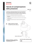
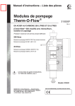
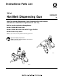
Hot Melt Dispensing Gun
309962H
EN
Used for manual dispensing of non flammable hot melt sealant
and adhesive materials. For professional use only.
Not for use in explosive atmospheres.
Model C34005 Bottom Feed
Model C34007 Bottom Feed with Trigger Switch
Model C50018 Top Feed
3500 psi (24.1 MPa, 241 bar) Maximum Working Pressure
Important Safety Instructions
Read all warnings and instructions in this manual.
Save these instructions.
ti13864
TI1629A
Table of Contents
Symbols . . . . . . . . . . . . . . . . . . . . . . . . . . . . . . . . . . . . . . 2
Warning . . . . . . . . . . . . . . . . . . . . . . . . . . . . . . . . . . . . . . . 2
Operation . . . . . . . . . . . . . . . . . . . . . . . . . . . . . . . . . . . . . 7
Troubleshooting . . . . . . . . . . . . . . . . . . . . . . . . . . . . . . . . 9
Service . . . . . . . . . . . . . . . . . . . . . . . . . . . . . . . . . . . . . . 10
2 309962
Parts . . . . . . . . . . . . . . . . . . . . . . . . . . . . . . . . . . . . . . . .
Technical Data . . . . . . . . . . . . . . . . . . . . . . . . . . . . . . . .
Graco Warranty . . . . . . . . . . . . . . . . . . . . . . . . . . . . . . .
Graco Information . . . . . . . . . . . . . . . . . . . . . . . . . . . . .
14
18
20
20
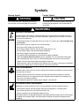
Symbols
Warning Symbol
Caution Symbol
WARNING
CAUTION
This symbol alerts you to the possibility of serious
injury or death if you do not follow the instructions.
This symbol alerts you to the possibility of damage to
or destruction of equipment if you do not follow the
instructions.
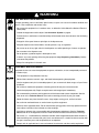
WARNING
SKIN INJECTION HAZARD
Spray from the gun, hose leaks, or ruptured components can inject fluid into your body and cause
extremely serious injury, including the need for amputation. Splashing fluid in the eyes or on the skin
can also cause serious injury.
D Fluid injected into the skin might look like just a cut, but it is a serious injury. Get immediate surgical treatment.
D Do not point the gun at anyone or at any part of the body.
D Do not put hand or fingers over the gun nozzle.
D Do not stop or deflect fluid leaks with your hand, body, glove, or rag.
D Be sure the gun trigger safety operates before dispensing.
D Lock the gun trigger safety when you stop dispensing.
D If the nozzle clogs while dispensing, fully release the trigger immediately
D Follow the Pressure Relief Procedure on page 7 whenever you: are instructed to relieve pressure; stop dispensing; clean, check, or service the equipment; and install or clean the nozzle.
D Tighten all the fluid connections before operating the equipment.
D Check the hoses, tubes, and couplings daily. Replace worn, damaged, or loose parts immediately.
Permanently coupled hoses cannot be repaired; replace the entire hose.
TOXIC FLUID HAZARD
Hazardous fluids or toxic fumes can cause a serious injury or death if splashed in the eyes or on the
skin, swallowed, or inhaled.
D Know the specific hazards of the fluid you are using. Read the fluid manufacturer’s warnings.
D Store hazardous fluid in an approved container. Dispose of the hazardous fluid according to all
local, state, and national guidelines.
D Wear appropriate protective clothing, gloves, eyewear, and respirator.
HOT SURFACE AND FLUID HAZARD
Heated fluid can cause severe burns and can cause equipment surfaces to become very hot.
D Wear protective gloves and clothing when operating this equipment in a heated system.
D Do not touch the metal heat sink when the surface is hot.
D Allow the equipment to cool thoroughly before servicing.
Some heated systems are designed to dispense Polyurethane (PUR) heated materials. PUR systems
are supplied with ventilation hoods, and require proper ventilation and specially designed system
components.
309962 3
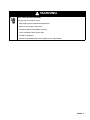
WARNING
FIRE AND EXPLOSION HAZARD
Improper grounding, poor air ventilation, open flames, or sparks can cause a hazardous condition and
result in a fire or explosion and serious injury.
D Do not use this equipment in a hazardous area, as defined in Article 500 of the National Electrical
Code (USA).
D Ground the equipment and the object. See Ground the System on page 6.
D Provide fresh air ventilation to avoid the buildup of flammable fumes from solvent or the fluid being
dispensed.
D Extinguish all the open flames or pilot lights in the dispense area.
D Keep the dispense area free of debris, including solvent, rags, and gasoline.
D Do not turn on or off any light switch in the dispense area while operating or if fumes are present.
D Do not smoke in the dispense area.
D Do not operate a gasoline engine in the dispense area.
D If there is any static sparking while using the equipment, stop dispensing immediately. Identify
and correct the problem.
D Keep a fire extinguisher in the work area.
EQUIPMENT MISUSE HAZARD
INSTRUCTIONS
Equipment misuse can cause the equipment to rupture, malfunction, or start unexpectedly and result
in a serious injury.
D This equipment is for professional use only.
D Read all the instruction manuals, tags, and labels before operating the equipment.
D Use the equipment only for its intended purpose. If you are uncertain about usage, call your Graco
distributor.
D Do not alter or modify this equipment. Use only genuine Graco parts and accessories.
D Check the equipment daily. Repair or replace worn or damaged parts immediately.
D Do not exceed the maximum working pressure of the lowest rated system component. See the
front cover or the Technical Data for the maximum working pressure of your gun model.
D Route the hoses away from the traffic areas, sharp edges, moving parts, and hot surfaces.
D Do not kink or overbend hoses or use the hoses to pull the equipment.
D Use only Graco approved hoses. Do not remove hose spring guards, which help protect the hose
from rupture caused by kinks or bends near the couplings.
D Use fluids or solvents that are compatible with the equipment wetted parts. See the Technical
Data section of all the equipment manuals. Read the fluid and solvent manufacturer’s warnings.
D Do not use 1,1, 1-trichloroethane, methylene chloride, other halogenated hydrocarbon solvents or
fluids containing such solvents with guns. Such use could result in a serious chemical reaction with
the gun’s aluminum parts, with the possibility of an explosion.
D Comply with all applicable local, state and national fire, electrical and other safety regulations.
4 309962
WARNING
ELECTRIC SHOCK HAZARD
To reduce the risk of electric shock
D Keep display panels fastened during operation
D Never cut or puncture a hose cover.
D Disconnect power source before servicing
D Install according to local electric code.
D Ground all equipment.
D Connect to grounded outlet. Do not expose to rain. Store indoors.
309962 5
Installation
Grounding the System
WARNING
FIRE AND EXPLOSION HAZARD
To reduce the risk of a fire, explosion,
and serious injury, proper electrical
grounding of every part of your system is
essential. Read the warning section,
FIRE AND EXPLOSION HAZARD, on
page 4 and follow the grounding
instructions below.
The following grounding instructions are minimum
requirements for a basic dispensing system. Your
system may include other equipment or objects which
must be grounded. Check your local electrical code for
detailed grounding instructions for your area and type
of equipment. Your system must be connected to a
true earth ground.
1. Fluid hoses: use only grounded fluid hoses with a
maximum of 25 feet (7.5 m) combined hose length
to ensure grounding continuity. Check the electrical
resistance of your fluid hoses at least once a
week. If your hose does not have a tag on it which
specifies the maximum electrical resistance,
contact the hose supplier or manufacturer for the
maximum resistance limits. If the hose resistance
exceeds the recommended limits, replace it immediately.
6 309962
2. Gun: The gun is grounded by connecting it to the
properly grounded fluid hose and by a ground wire
in the cable. Check ground continuity between the
gun body and the heat control ground lug.
3. Fluid supply container: ground according to the
local code.
4. Flammable liquids in the dispense area: must
be kept in approved, grounded containers. Do not
store more than the quantity needed for one shift.
5. All solvent pails used when flushing: ground
according to local code. Use only metal pails,
which are conductive. Do not place the pail on a
non-conductive surface, such as paper or cardboard, which interrupts the grounding continuity.
6. To maintain grounding continuity when flushing or relieving pressure: hold a metal part of
the gun firmly to the side of a grounded metal pail,
then trigger the gun.
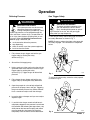
Operation
Relieving Pressure
Gun Trigger Safety
WARNING
WARNING
SKIN INJECTION HAZARD
The system pressure must be manually
relieved to prevent the system from
starting or dispensing accidentally. Fluid
under high pressure can be injected through the
skin and cause a serious injury. To reduce the risk
of an injury from injection, splashing fluid, or moving parts, follow the Relieving Pressure Procedure on page 7 whenever you:
D
D
D
D
are instructed to relieve the pressure,
stop dispensing,
check or service any of the system equipment,
install or clean the nozzle.
SKIN INJECTION HAZARD
To prevent accidental triggering of the
gun and reduce the risk of a serious
injury, including fluid injection or splashing in the eyes or on skin, lock the gun trigger
safety when you stop dispensing.
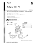
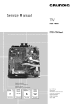
To lock the gun safety, release the trigger and rotate
the safety downward as shown in Fig. 1.
NOTE: Do not try to force the trigger valve open with
the safety engaged. This could result in component
failure.
1. Fully release the gun trigger and lock the gun
trigger safety by rotating the safety
downward (Fig. 1).
Locked
2. Shut off the fluid supply pump.
3. Hold a metal part of the gun firmly to the side of a
grounded metal waste container. Unlock the gun
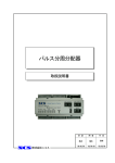
trigger safety by rotating the safety
upward (Fig. 2). Trigger the gun to relieve fluid
pressure.
4. Fully release the gun trigger and lock the gun
trigger safety by rotating the safety downward.
Fig. 1
TI0372
To unlock the trigger safety, rotate the safety upward
as shown in Fig. 2.
5. Open the pump drain valve to help relieve fluid
pressure in the pump, hose, and gun. Triggering
the gun to relieve pressure may not be sufficient.
Have a container ready to catch the drainage.
Unlocked
6. Leave the drain valve open until you are ready to
dispense again.
7. If you think that the gun nozzle or fluid hose is
completely clogged or that pressure has not been
fully relieved after following the steps above, very
slowly loosen the hose end coupling and relieve
pressure gradually, then loosen the coupling
completely. Clear the nozzle or hose obstruction.
Fig. 2
TI0372
309962 7
Operation
Heating Up the Gun and System
WARNING
PRESSURE RUPTURE HAZARD
Heating fluid expands, causing a rise in
pressure in a closed system.
D Be sure pressure is relieved before
heating up the equipment. Follow the
pressure Relieving Pressure Procedure on page 7.
D Engage trigger retainer to hold
dispense gun open to prevent excessive pressure build-up from fluid
expansion
1. Be sure pump is off.
2. Engage the dispense gun trigger retainer to hold
the valve open.
3. Activate the heat controls.
3. Unlock the gun trigger safety.
4. Squeeze the trigger in all the way. Fluid flow
begins with the slightest pressure on the trigger
and stops when the trigger is released.
Flushing Safety
WARNING
FIRE AND EXPLOSION HAZARD
To reduce the risk of a fire, explosion, or
serious injury,
D Be sure the entire system and flushing pails are properly grounded
before flushing the gun or system.
Read Grounding the System, on page 6.
D Use the lowest possible fluid pressure and
maintain firm metal-to-metal contact between
the gun and the grounded metal pail during
flushing.
D Heat controls must be off during flushing if
solvents are used to flush.
4. After pump, hose, and gun are up to temperature,
disengage gun trigger retainer to close the valve.
Engage the gun trigger safety to prevent accidental dispense of high pressure heated fluid.
Shutting Down
Dispensing
1. Turn off all heat at the controller.
1. Start the fluid supply pump.
2. Turn off fluid pump.
2. The fluid flow rate is controlled at the pump. Adjust
the pump pressure to obtain the desired flow rate.
It is recommended that you use the lowest pressure necessary to dispense the fluid. The pressure
adjustment will depend on the hose length, the
viscosity of the fluid, and the gun nozzle size.
3. Trigger gun to relieve pressure while system is still
hot.
8 309962
4. With gun over a waste container, engage gun
trigger retainer to hold valve open for next heat-up
cycle.
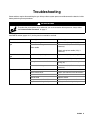
Troubleshooting
Some solutions require disassembling the gun. Always relieve system pressure and disconnect the electrical cable
before performing these procedures.
WARNING
To reduce the risk of serious injury whenever you are instructed to relieve pressure, always follow
the Pressure Relief Procedure on page 7.
See PARTS section (pages 14-17) for the parts that need to be serviced.
Problem
Cause(s)
Solution(s)
Material leaks from front of
gun
Seat or packing is worn
Replace seat (18 or packing (20).
Obstruction inside gun
Remove seat (18). Check and replace if
necessary.
Worn needle
Check and replace needle (15a), if
necessary.
Material leaks from back of
gun
Needle seal or packing is worn
Replace seals (15c) or packing (15d).
Gun does not shut off
Needle or adapter is worn
Replace needle (15a) or adapter (19).
Spring broken or not installed correctly
Check and replace, if necessary,
spring (16).
Obstruction inside gun
Remove seat (18). Check and replace if
necessary.
Loose heater wires
Check and reconnect wire connections.
Loose sensor wires
Check and reconnect wire connections.
Heater unit failed
Replace heater.
Sensor failed
Replace sensor.
Temperature controller failed
Replace temperature controller.
No power to heating circuitry
Apply power to heating circuitry.
Gun does not heat material
309962 9
Service
WARNING
SKIN INJECTION HAZARD
To reduce the risk of a serious injury,
including fluid injection,
D Follow the Pressure Relief Procedure on page
7 when you stop dispensing, before servicing
the gun, and whenever you are instructed to
relieve the pressure.
D After adjusting or servicing the gun, make sure
the fluid will not trigger on when the trigger
safety is locked. If fluid does flow, the gun is not
assembled properly or the trigger safety is
damaged. Reassemble the gun or return it to
your nearest Graco distributor. Do not use the
gun until the problem is corrected.
SERVICE NOTES:
WARNING
SKIN INJECTION HAZARD
To reduce the risk of a serious injury,
including fluid injection, if fluid continues
to flow after the trigger is released,
service the gun immediately as instructed below.
Do not use the gun until the problem is corrected.
3. The following repair kit is available:
Repair Kit Gun Model
C32002
Manual Hot–Melt Guns C34005,
C34007, and C50018
Installing new heater unit, RTD sensor, or
switch
1. Open the connector (24) by removing the screw on
the side and pulling out insert (25).
2. For Therm–O–Flow 6 pin assemblies, removal and
replacement of the heaters and RTD require a pin
extraction tool, new connector pins, and a pin
crimping tool. These tools meet spec
MIL–C–22520 (Ref. Daniels AF8 crimp tool) or
equivalent, available at your local industrial electrical supply warehouse. Soldering the new leads is
an acceptable alternative as long as new pins (27)
are used.
3. Remove the faulty sensor or heater by cutting the
leads at the connector and pulling the wires back
through the conduit and out of the gun.
4. Use the pin extraction tool to punch out the old
pins.
5. Coat heater or sensor with heat sink compound.
NOTE: Items in ( ) refer to items in the PARTS list.
1. If the fluid continues to flow after the trigger is
released, the gun valve may need adjustment, be
obstructed or damaged, or the needle
assembly (15) or seat (18) may be worn or damaged.
6. Gently slide new heater or sensor into appropriate
hole.
7. Feed the new wires through the conduit to the
connector. On bottom entry models, be sure to use
protective sleeve (31) over wires where they pass
through needle area.
a. Adjust the spring tension as instructed on
page 13.
8. Cut and strip the wires to the appropriate length.
b. Replace the needle assembly (15) or
seat (18) as instructed on page 13.
9. Slide 1/8” diameter heat shrink tubing over the
wires.
2. Follow the torque, sealant and lubrication notes for
your gun model number.
10 309962
10. Crimp or solder the wires to the appropriate new
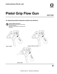
connector pin as shown in Fig. 3.
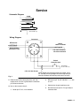
Service
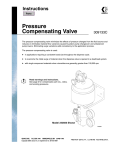
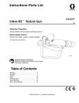
Schematic Diagram
F
C
A
B
E
GUN SWITCH
D
(Model C34007 only)
Wiring Diagram
Connector
RTD Sensor
B
Approximately
108 ohms @ 70_F
C
A
D
Heater
100W @ 120VAC
F
123 ohms minimum–
150 ohms maximum
E
Switch
Normally Open
GUN SWITCH
(Model C34007 only)
6 Pin 120 Volt Shown
Fig. 3
NOTE: Route switch wiring through gun handle, insulator, and body, ensuring enough slack to change over gun
from top to bottom inlet without putting strain on wires.
11. Slide the heat shrink tubing into place and thoroughly shrink it so that it grabs onto the connector
pin and wire insulation.
b. RTD sensor pin A to B, 108 ohms ohm
at 70_F.
c.
Continuity to the gun body from pin 8
12. Use an ohm meter to check:
a. heater pins F to C, 123–150 ohms
d. No continuity from pins A–F to gun body or
connector shell.
309962 11
Service
Inspection Frequency
Adjusting the Needle Assembly
Dispense Valve
The trigger travel and corresponding valve opening are
factory set. To adjust this setting, follow the procedure
below.
Inspect dispense valve at every use for leakage or
other visible damage.
Heater
Every two weeks, check heater for proper resistance.
Resistance should be approximately 123–150 ohms
(+58/–29) cold for the 120 volt valves. Replace heater
if necessary.
Also inspect heater when performing regular maintenance procedures.
Sensor
Every two weeks, check sensor resistance. Resistance
should be 108 ohms at 21° C (70° F). Replace sensor
if necessary.
Also inspect sensor when performing regular maintenance procedures.
WARNING
SKIN INJECTION HAZARD
To reduce the risk of a serious injury, including fluid injection, follow the Pressure
Relief Procedure on page 7 whenever you
are instructed to relieve the pressure.
NOTE: Items in ( ) refer to items in the PARTS list
(pages 14-17).
1. Relieve the pressure in the system.
2. Disconnect the gun from the hose.
3. Using a 1/2 in. and 11/32 in. wrench, loosen hex
nut (15m).
4. Remove nozzle (19), cap (5) and shield (4).
5. Trigger gun and, using a screwdriver in the slot of
the needle, turn the needle clockwise several
turns.
6. Release the trigger, turn the needle counterclockwise until it contacts the seat
7. Trigger the gun, and turn the needle one additional
turn counterclockwise.
8. Tighten the hex nuts (15m) to set the adjustment.
9. Reassemble shield (4), cap (5), and nozzle (19).
12 309962
Service
Adjusting the Spring Tension
WARNING
SKIN INJECTION HAZARD
To reduce the risk of a serious injury,
including fluid injection, follow the
Pressure Relief Procedure on page 7
whenever you are instructed to relieve the
pressure.
NOTE: Items in ( ) refer to items in the PARTS list
(pages 14-17).
Servicing Valve Stem and Seal
If fluid leaks past seal (15c), the seal or needle (15a)
may be worn or damaged. To replace the seal or valve
stem, follow the procedure below.
WARNING
SKIN INJECTION HAZARD
To reduce the risk of a serious injury,
including fluid injection, follow the
Pressure Relief Procedure on page 7
whenever you are instructed to relieve the
pressure.
1. Relieve the pressure in the system.
1. Relieve the pressure in the system.
NOTE: For models with switch (42); cover (43) must
be removed and the switch must be removed.
2. Disconnect the gun from the hose.
2. Loosen lock nut (13).
NOTE: For models with switch (42); cover (43) must
be removed and the switch must be removed.
3. Loosen lock nut (13).
3. Adjust the spring retainer (39) to the desired
trigger pull force.
4. Tighten lock nut (13) to secure spring tension
adjustment.
4. Unscrew the spring retainer (Item 39).
5. Using a 1/2 in. and 11/32 in. wrench, loosen hex
nut (Item15m).
6. Remove nozzle (19), cap (5), and shield (4).
7. Trigger gun and, using a screwdriver in the slot of
the needle (15a), turn the needle clockwise several
turns.
8. While holding the yoke (15g), turn needle (15a)
counterclockwise until it separates.
9. Remove the front half of the needle assembly
(15a) from the gun.
10. Remove and replace packing support (15b),
needle seals (15c), and O–ring packing (15d).
11. Install the front half of the needle assembly in the
body (1)
12. While holding yoke (15g), install the needle (15a),
rotating clockwise.
13. Adjust the needle as described in Adjusting the
Needle Assembly on page 12.
14. Install shield (4), cap (5), and nozzle (19).
15. If necessary, adjust spring tension as described in
Adjusting the Spring Tension on this page.
309962 13
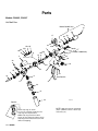
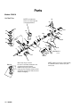
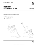
Parts
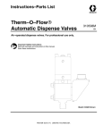
Models C34005, C34007
Hot Melt Gun
Model C34007 only
14
50
49
17
48
13
28
29
15c
15b
15e 15f
15d
10
16
1
15
13
15g
15m
35
14
39
Model C34005 only
34
33
4
26
15a
23
21
3
20
5
2
12
18
19
8
52
11
See Detail A
6
17
9
43
51
42
ti23571a
Detail A
Orient snap rings as shown.
For ease of assembly, install pins and
snap rings from top to bottom.
Middle snap ring must be installed
facing up, then rotated to position shown.
Snap rings must be flush with each other
without overlapping.
14 309962
NOTE: Apply heat transfer compound
(30) to cylindrical surface of heater (27)
and sensor (21).
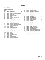
Parts
Model C34005
Manual Hot Melt Gun
Model C34007
Trigger Switch Hot Melt Gun
Ref.
No.
1
2
3
4
5
6
Part No.
C34010
C32028
C32011
C31017
C31016
156849
C57733
C32368
C27051
C32004
C19208
15X116
C27036
111821
Description
Qty.
BODY, hot-melt, manual gun
INSULATOR, hot-melt hand gun
BODY, gun
SHIELD, hand gun
CAP
FITTING, pipe 3/8 in. npt
SWIVEL, 3/8 in. npt (F)
8
RING
9
TRIGGER
10
HANGER, gun
11
WASHER, lock
12
PIN, trigger
13
NUT, lock
14
SCREW, cap, socket head
(Model C34005)
(Model C34007)
15
918530
NEEDLE, assembly (consists of
. . . . . . . . . . . . . . . . items 15a through 15m
15a
C27038
NEEDLE
15b
C27053
SUPPORT, packing
15c* C27060
SEAL, needle
15d* 103338
PACKING, O–ring
15e
C32027
NUT, packing
15f
C27061
SCREW, adjustment
15g
15C749
YOKE, trigger, handgun
15m C19284
NUT
16
C00020
SPRING
17
100284
NUT, hex, MSCR
18*
C27014
SEAT
1
1
1
1
1
1
1
1
1
3
3
1
2
3
1
1
1
3
1
1
1
1
1
1
3
1
Ref.
No.
Part No.
Description
19
20*
21
22
23
26
28
29
30
31
33
34
35
39
42
43
44
45
48
49
50
51
52
C32003
103610
C32255
198511
C19156
617838
C19977
157021
C07664
15A506
108483
C34009
C20565
C27037{
C31021
C57733
116675
116673
C32369}
C32368}
C32371}
C20769
C19950
NOZZLE
PACKING, o–ring
SENSOR, temperature
ADAPTER, connector, manual
SCREW, socket head
HEATER, cartridge, 100W, 120V
SCREW, cap, socket head
WASHER, lock, internal
Thermal compound (3 oz)
SLEEVE, protective
SCREW, shoulder
TRIGGER LOCK
WASHER, spring
RETAINER, spring
COVER, sponge
SWIVEL, hose
CONDUIT, metal flex
BUSHING, strain relief
RETAINER, spring
SWITCH
COVER, switch
FITTING, connector, male
SCREW, cap
*
Qty.
1
1
1
1
5
1
1
1
1
2
1
1
1
1
1
1
1
1
1
1
1
1
3
These parts are included in Repair Kit C32002,
which may be purchased separately.
{ Model C34005 only.
} Model C34007 only.
309962 15
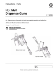
Parts
Models C50018
Hot Melt Gun
NOTE: Assemble two
10
halves over swivel (6) after
connecting fluid hose.
29
17
28
50
1
48
16
53
13
47
15g
15
47
35
15m
14
34
6
21
26
39
33
12
49
8
9
20
18
15a 2
5
3
17
19
15f
15e
15d
15c
15b
52
11
See Detail A
ti23569a
4
Detail A
16 309962
Orient snap rings as shown.
For ease of assembly, install pins and
snap rings from top to bottom.
Middle snap ring must be installed
facing up, then rotated to position shown.
Snap rings must be flush with each other
without overlapping.
NOTE: Apply heat transfer compound (58)
to cylindrical surface of heater (27) and
sensor (22).
Parts
Model C50018
Manual Hot Melt Gun
Ref.
No.
Part No.
Description
Ref.
No.
26
28
29
31
33
34
35
38
39
44
46
47
48
C31031
C19977
157021
617836
108483
C34009
C20565
112385
C32369
C07535
C07536
C51071
C78480
49
50
52
53
54
55
56
57
58
C32005
C19952
C19950
C33241
116675
116673
198422
198442
C07664
HEATER, cartridge
1
SCREW, cap, socket head
1
WASHER, lock, internal
1
SLEEVE, fiberglass braid, #10, blk 1
SCREW, shoulder SCH
1
TRIGGER LOCK
1
WASHER, spring
1
SCREW, set
2
RETAINER, spring
1
TUBE, heat, shrink
1
TUBE, heat shrink
.2 ft
GASKET
2
ADAPTER, connector, manual
gun top
1
COVER, wires
1
SCREW, socket head
4
SCREW, cap
3
KIT, accessory, stop
1
CORD, flex, valve, 1K
1
BUSHING, strain relief
1
COVER, protective
1
STRAP, retaining mix manifold
2
Heat transfer compound (3 oz)
1
Part No.
1
C32022
2
C32028
3
C32012
4
C31017
5
C31016
6
C20483
8
C32368
9
C27051
10
C32004
11
C19208
12
15X116
13
C27036
14
111821
15
918530
................
15a
C27038
15b
C27053
15c* C27060
15d* 103338
15e
C32027
15f
C27061
15g
15C749
15m C19284
16
C00020
17
C27037
18*
C27014
20*
103610
21
C32255
22
196508
23
102410
Description
Qty.
BODY, hot-melt, manual gun, flow
INSULATOR, hot-melt handgun
BODY, gun
SHIELD, handgun
CAP
FITTING, pipe, 3/8 in. npt
RING
TRIGGER, gun
HANGER, gun
WASHER, lock
PIN, trigger
NUT, lock
SCREW, cap, socket head
NEEDLE, assembly (consists of
items 15a through 15m
NEEDLE
SUPPORT, packing
SEAL, needle
PACKING, O–ring
NUT, packing
SCREW, adjustment
YOKE, trigger, handgun
NUT
SPRING
RETAINER, spring
SEAT
PACKING, O-ring
SENSOR, temperature
PLUG
SCREW
1
1
1
1
1
1
1
1
1
3
3
1
2
1
1
1
3
1
1
1
1
1
1
1
1
1
1
1
4
*
Qty.
These parts are included in Repair Kit C32002,
which may be purchased separately. See page 10
for complete Repair Kit list.
309962 17
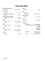
Technical Data
Maximum Working Pressure
All Models . . . . . . . . . . . . . . . . . . 3500 psi (241 bar)
Outlet Port Size
All Models . . . . . . . . . . . . . . . . . . . . . . . . . . 1/4 npt(f)
Inlet Port Size on Gun Housing
All Models . . . . . . . . . . . . . . . . . . . . . . . . . . 3/8 npt(f)
Inlet Port Size on Fluid Swivel
All Models except C50018 . . . . . . . . . . . 7/8 JIC(m)
C50018 . . . . . . . . . . . . . . . . . . . . . . . . . . . . . 1/2 npt(f)
Height
Wattage
All Models . . . . . . . . . . . . . . . . . . . . . . . . . . . . 100 W
RTD
Platinum RTD
.00385 ohms/_C . . . . . . . . . . . 108.2 ohms @70_F
Heater Resistance
All Models . . . . . . . . . . . . . . . . . . . . . 123–150 ohms
Weight
All Models . . . . . . . . . . . . . . . . . . . . 3.5 lbs. (1.6 kg)
C34005 and C34007 . . . . . . . . . 8.25 in. (210 mm)
C50018 . . . . . . . . . . . . . . . . . . . . . . . 10 in. (254 mm)
Width
C34005 and C34007 . . . . . . . . . . 2.15 in. (55 mm)
C50018 . . . . . . . . . . . . . . . . . . . . . . 3.72 in. (95 mm)
Length
2435197 and C34007 . . . . . . . 12.54 in. (319 mm)
Wetted Parts
All Models
Fluid Section . . . . . . . . . . . . . Hardened Steel,
fluoroelastomer, AFLAS and PTFE Seals,
12L14 Steel,
1215 CRS,
4140 SST,
Chrome Alloy,
Black Oxide
C50018 . . . . . . . . . . . . . . . . . . . . 11.91 in. (303 mm)
Voltage
All Models . . . . . . . . . . . . . . . . . . . . . . . . . . 120 VAC
18 309962
Valve Needle . . . . . . . . . . Tool Steel shaft with
chrome alloy ball
Valve Seat . . . . . . . . . . . Hardened Steel RC52
Notes
309962 19
Graco Standard Warranty
Graco warrants all equipment manufactured by Graco and bearing its name to be free from defects in material and workmanship on the
date of sale to the original purchaser for use. With the exception of any special, extended, or limited warranty published by Graco,
Graco will, for a period of twelve months from the date of sale, repair or replace any part of the equipment determined by Graco to be
defective. This warranty applies only when the equipment is installed, operated and maintained in accordance with Graco’s written
recommendations.
This warranty does not cover, and Graco shall not be liable for general wear and tear, or any malfunction, damage or wear caused by
faulty installation, misapplication, abrasion, corrosion, inadequate or improper maintenance, negligence, accident, tampering, or substitution of non–Graco component parts. Nor shall Graco be liable for malfunction, damage or wear caused by the incompatibility of
Graco equipment with structures, accessories, equipment or materials not supplied by Graco, or the improper design, manufacture,
installation, operation or maintenance of structures, accessories, equipment or materials not supplied by Graco.
This warranty is conditioned upon the prepaid return of the equipment claimed to be defective to an authorized Graco distributor for
verification of the claimed defect. If the claimed defect is verified, Graco will repair or replace free of charge any defective parts. The
equipment will be returned to the original purchaser transportation prepaid. If inspection of the equipment does not disclose any defect
in material or workmanship, repairs will be made at a reasonable charge, which charges may include the costs of parts, labor, and
transportation.
THIS WARRANTY IS EXCLUSIVE, AND IS IN LIEU OF ANY OTHER WARRANTIES, EXPRESS OR IMPLIED, INCLUDING BUT
NOT LIMITED TO WARRANTY OF MERCHANTABILITY OR WARRANTY OF FITNESS FOR A PARTICULAR PURPOSE.
Graco’s sole obligation and buyer’s sole remedy for any breach of warranty shall be as set forth above. The buyer agrees that no other
remedy (including, but not limited to, incidental or consequential damages for lost profits, lost sales, injury to person or property, or any
other incidental or consequential loss) shall be available. Any action for breach of warranty must be brought within two (2) years of the
date of sale.
Graco makes no warranty, and disclaims all implied warranties of merchantability and fitness for a particular purpose in connection
with accessories, equipment, materials or components sold but not manufactured by Graco. These items sold, but not manufactured
by Graco (such as electric motors, switches, hose, etc.), are subject to the warranty, if any, of their manufacturer. Graco will provide
purchaser with reasonable assistance in making any claim for breach of these warranties.
In no event will Graco be liable for indirect, incidental, special or consequential damages resulting from Graco supplying equipment
hereunder, or the furnishing, performance, or use of any products or other goods sold hereto, whether due to a breach of contract,
breach of warranty, the negligence of Graco, or otherwise.
FOR GRACO CANADA CUSTOMERS
The parties acknowledge that they have required that the present document, as well as all documents, notices and legal proceedings
entered into, given or instituted pursuant hereto or relating directly or indirectly hereto, be drawn up in English. Les parties reconnaissent avoir convenu que la rédaction du présente document sera en Anglais, ainsi que tous documents, avis et procédures judiciaires
exécutés, donnés ou intentés à la suite de ou en rapport, directement ou indirectement, avec les procedures concernées.
Graco Information
For the latest information about Graco products, visit www.graco.com.
TO PLACE AN ORDER, contact your Graco distributor or call to identify the distributor closest to you:
Phone: 612–623–6921 or Toll Free: 1–800–328–0211 Fax: 612–378–3505
All written and visual data contained in this document reflects the latest product information available at the time of publication.
Graco reserves the right to make changes at any time without notice.
For patent information, see www.graco.com/patents.
Original instructions. This manual contains English. MM 309962
Graco Headquarters: Minneapolis
International Offices: Belgium, China, Japan, Korea
GRACO INC. AND SUBSIDIARIES S P.O. BOX 1441 S MINNEAPOLIS MN 55440–1441 S USA
Copyright 2001, Graco Inc. All Graco manufacturing locations are registered to ISO 9001.
www.graco.com
Revision H, April 2014
20 309962