1
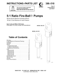
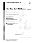
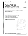
Instructions–Parts List
1:1 RATIO
TRITONR 308
Diaphragm Pump
309303V
ENG
Used to pump waterborne and solvent–based paints and catalysts. For
professional use only.
115 psi (0.8 MPa, 8 bar) Maximum Fluid Working Pressure
115 psi (0.8 MPa, 8 bar) Maximum Air Input Pressure
Part No. 233500 Aluminum Pump, Series D, npt threads
Part No. 233501 Stainless Steel Pump, Series C, npt threads
Part No. 233776 Aluminum Pump, Series C, BSPP threads
Part No. 233777 Stainless Steel, Series C, BSPP threads
U.S. and Foreign Patents Pending
Important Safety Instructions
Read all warnings and instructions in this manual.
Save these instructions.
Part No. 233501 Shown
ti1029a
Table of Contents
Safety Warnings . . . . . . . . . . . . . . . . . . . . . . . . . . . . . . . 3
Installation . . . . . . . . . . . . . . . . . . . . . . . . . . . . . . . . . . . . . 6
Operation . . . . . . . . . . . . . . . . . . . . . . . . . . . . . . . . . . . . 11
Maintenance . . . . . . . . . . . . . . . . . . . . . . . . . . . . . . . . . . 12
Troubleshooting . . . . . . . . . . . . . . . . . . . . . . . . . . . . . . . 12
Service
Remove the Fluid and Side Covers . . . . . . . . . . . 14
Ball Check Repair . . . . . . . . . . . . . . . . . . . . . . . . . . 16
Diaphragm Repair . . . . . . . . . . . . . . . . . . . . . . . . . . 17
Air Valve Repair . . . . . . . . . . . . . . . . . . . . . . . . . . . . 18
Shaft Repair . . . . . . . . . . . . . . . . . . . . . . . . . . . . . . . 20
Parts . . . . . . . . . . . . . . . . . . . . . . . . . . . . . . . . . . . . . . . . 23
Technical Data . . . . . . . . . . . . . . . . . . . . . . . . . . . . . . . . 24
Dimensions . . . . . . . . . . . . . . . . . . . . . . . . . . . . . . . . . . . 25
Graco Standard Warranty . . . . . . . . . . . . . . . . . . . . . . 26
Graco Information . . . . . . . . . . . . . . . . . . . . . . . . . . . . . 26
2
309303
Symbols
Warning Symbol
WARNING
This symbol alerts you to the possibility of serious
injury or death if you do not follow the instructions.
Caution Symbol
CAUTION
This symbol alerts you to the possibility of damage to
or destruction of equipment if you do not follow the
instructions.
WARNING
EQUIPMENT MISUSE HAZARD
INSTRUCTIONS
Equipment misuse can cause the equipment to rupture, malfunction, or start unexpectedly and result
in a serious injury.
This equipment is for professional use only.
Read all instruction manuals, tags, and labels before operating the equipment.
Use the equipment only for its intended purpose. If you are not sure, call your Graco distributor.
Do not alter or modify this equipment. Use only genuine Graco parts and accessories.
Check equipment daily. Repair or replace worn or damaged parts immediately.
Do not exceed the maximum working pressure of the lowest rated component in your system. This
equipment has a 115 psi (0.8 MPa, 8 bar) maximum working pressure at 115 psi (0.8 MPa, 8
bar) maximum incoming air pressure.
Use fluids and solvents which are compatible with the equipment wetted parts. Refer to the Technical Data section of all equipment manuals. Read the fluid and solvent manufacturer’s warnings.
Aluminum pumps only: Never use 1.1.1–trichloroethane, methylene chloride, other halogenated
hydrocarbon solvents or fluids containing such solvents in pressurized aluminum equipment. Such
use could result in a chemical reaction, with the possibility of explosion.
Do not use hoses to pull equipment.
Route hoses away from traffic areas, sharp edges, moving parts, and hot surfaces. Do not expose
Graco hoses to temperatures above 180F (82C) or below –40F (–40C).
Wear hearing protection when operating this equipment.
Comply with all applicable local, state, and national fire, electrical, and safety regulations.
309303
3
WARNING
FIRE AND EXPLOSION HAZARD
Improper grounding, poor air ventilation, open flames, or sparks can cause a hazardous condition and
result in fire or explosion and serious injury.
Ground the equipment. Refer to Grounding on page 7.
If there is any static sparking or you feel an electric shock while using this equipment, stop pumping immediately. Do not use the equipment until you identify and correct the problem.
Provide fresh air ventilation to avoid the buildup of flammable fumes from solvents or the fluid
being pumped.
Keep the work area free of debris, including solvent, rags, and gasoline.
Electrically disconnect all equipment in the work area.
Extinguish all open flames or pilot lights in the work area.
Do not smoke in the work area.
Do not turn on or off any light switch in the work area while operating or if fumes are present.
Do not operate a gasoline engine in the work area.
4
309303
WARNING
PRESSURIZED FLUID HAZARD
Spray from the gun, hose leaks, or ruptured components can splash fluid in the eyes or on the skin
and cause serious injury.
Do not stop or deflect fluid leaks with your hand, glove, or rag.
Follow the Pressure Relief Procedure on page 11 before cleaning, checking, or servicing the
equipment.
Tighten all fluid connections before each use.
Check the hoses, tubes, and couplings daily. Replace parts immediately if worn, damaged, or
loose. Permanently coupled hoses cannot be repaired.
TOXIC FLUID HAZARD
Hazardous fluids or toxic fumes can cause a serious injury or death if splashed in the eyes or on the
skin, swallowed, or inhaled.
Know the specific hazards of the fluid you are using. Read the fluid manufacturer’s warnings.
Store hazardous fluid in an approved container. Dispose of the hazardous fluid according to all
local, state, and national guidelines.
Wear appropriate protective clothing, gloves, eyewear, and respirator.
If the diaphragm fails, the fluid is exhausted along with the air.
309303
5
Installation
General Information
Fig. 2 shows a wall mounted HVLP spray application. It is only a guide for selecting and installing
system components. Contact your Graco distributor
for assistance in planning a system to suit your
needs.
Always use Genuine Graco Parts and Accessories,
available from your Graco distributor. If you supply
your own accessories, be sure they are adequately
sized and pressure rated for your system.
Use a compatible, liquid thread sealant on all male
threads. Tighten all connections firmly to avoid air
or fluid leaks.
NOTE: On all npt threads, tighten to 2–3 turns past
finger tight.
Reference numbers and letters in parentheses refer
to the callouts in the figures and the parts lists on
pages 23–22.
In a spray system, ventilate the spray booth.
Tightening Threaded Fasteners Before
First Use
NOTE: Before using pump, loosen fluid cover screws
(38) 1–2 turns and then retorque to 13.6 Nm
(10 ft–lb).
See the Service section for torque specifications.
After unpacking the pump, and before using it for
the first time, check and retorque all external fasteners.
After the first day of operation, retorque the fasteners.
As a general guideline, retorque fasteners every
two months.
6
309303
WARNING
FIRE AND EXPLOSION HAZARD
To prevent hazardous concentrations of
toxic and/or flammable vapors, spray
only in a properly ventilated spray booth.
Never operate the spray gun unless
ventilation fans are operating.
Check and follow all of the national,
state, and local codes regarding air
exhaust velocity requirements.
WARNING
TOXIC FLUID HAZARD
Hazardous fluid or toxic fumes can
cause serious injury or death if splashed
in the eyes or on the skin, inhaled, or
swallowed.
1. Read TOXIC FLUID HAZARD on page 5.
2. Use fluids and solvents which are compatible
with the equipment wetted parts. Refer to the
Technical Data section of all equipment manuals. Read the fluid and solvent manufacturer’s
warnings.
Mounting the Pump
Mount the pump in a well-ventilated area, with
sufficient clearance on all sides for operator access
and servicing.
Be sure the mounting can support the weight of the
pump, hoses, and accessories, as well as the
stress caused during operation.
The pump may be mounted vertically or horizontally. Be sure the pump is level in all directions.
Wall, pail, stand, or portable cart mounting kits are
available from Graco. For other mountings, be sure
the pump is adequately secured. The pump has
two mounting holes for 0.35 in. (9 mm) screws. See
the Dimension drawing on page 25.
Installation
Grounding
35
Y
WARNING
FIRE AND EXPLOSION HAZARD
This pump must be grounded. Before
operating the pump, ground the system
as explained below. Also read the section FIRE AND EXPLOSION HAZARD
on page 4.
To reduce the risk of static sparking, ground the pump
and all other equipment used or located in the pumping
area. Check your local electrical code for detailed
grounding instructions for your area and type of equipment.
Ground all of this equipment:
Pump: Attach a ground wire (Y) to the pump’s
grounding screw (35) and secure with the screw, as
shown in Fig. 1. Connect the clamp end of the
ground wire to a true earth ground. Order Part No.
238909 Ground Wire and Clamp.
ti1030b
Fig. 1
Air and fluid hoses: Use only electrically conductive
hoses.
Air compressor: Follow the manufacturer’s recommendations.
Solvent pails used when flushing: Follow your local
code. Use only metal pails, which are conductive.
Do not place the pail on a non-conductive surface,
such as paper or cardboard, which interrupts the
grounding continuity.
Fluid supply container: Follow your local code.
309303
7
Installation
Air Line
WARNING
A bleed-type master air valve (B) is required in your
system to relieve air trapped between this valve
and the pump. See Fig. 2. Trapped air can cause
the pump to cycle unexpectedly, which could result
in serious injury, including splashing in the eyes or
on the skin, injury from moving parts, or contamination from hazardous fluids.
b. Locate a bleed-type master air valve (B) close
to the pump, to relieve trapped air. See the
WARNING at left. Locate another air valve (E)
upstream from all air line accessories, to
isolate them during cleaning and repair.
c.
Install an air line filter (D) to remove harmful
contaminants such as dirt, moisture, and oil
from the compressed air supply.
2. The air valve does not require lubrication.
1. Install the air line accessories as shown in Fig. 2.
Mount these accessories on the wall or on a
bracket. Be sure the air line supplying the accessories is electrically conductive.
a. The fluid pressure can be controlled in two
ways, either by controlling the air into the
pump with the air regulator (F) or the fluid out
of the pump with the fluid regulator (H).
8
309303
3. Install an electrically conductive, flexible air hose
(C) between the accessories and the pump air inlet
(T). Use a minimum 1/4” (6.3 mm) ID air hose.
Screw an air line quick disconnect coupler (V) onto
the end of the air hose and screw the mating fitting
into the pump air inlet snugly. Do not connect the
coupler to the fitting yet.
Installation
Wall Mount HVLP Spray Installation Shown
KEY
A
B
TRITON 308 Pump
Bleed-type master air valve
(required for pump)
C Air supply line
D Air line filter
E Air line shutoff valve
F Pump air regulator
G Gun air regulator (used in spray system only)
H Fluid pressure regulator (used in spray
system only)
J Drain/circulation valve
K Drain tube
L Suction tube
M Pump fluid inlet
N Pump fluid outlet
P Fluid hose (shown connected to gun in spray
system)
R Gun air hose (used in spray system only)
S Spray gun (used in spray system only)
T Pump air inlet
U Agitator (used in spray system only)
V Air line quick disconnect
Y Ground wire
S
H
E
D
Y
R
J
P
B
V
C
L
U
Y
K
J
H
N
ti1020a
K
G
T
F
A
M
L
B
ti1007a
Fig. 2
309303
9
Installation
Fluid Suction Line
Screw the suction line (L) into the pump inlet (M)
snugly. Use a compatible liquid thread sealant on
connections to prevent air from getting into the fluid
line.
Do not pressure feed this pump.
See the Technical Data on page 24 for maximum
suction lift.
Use an agitator (U) to prevent fluid from settling
out. Part No. 245081 Agitator Kit (accessory) is
available.
Fluid Outlet Line
WARNING
A fluid drain valve (J) is required in your system to
relieve pressure in the hose if it is plugged. See
Fig. 2. The drain valve reduces the risk of serious
injury, including splashing in the eyes or on the
skin, or contamination from hazardous fluids when
relieving pressure. Install the valve close to the
pump fluid outlet. To use the valve as a circulation
valve, connect a tube (K) between the valve and
pail.
10
309303
CAUTION
Some systems may require installation of a pressure
relief valve at the pump outlet to prevent overpressurization and rupture of the pump or hose.
Thermal expansion of fluid in the outlet line can
cause overpressurization. This can occur when using
long fluid lines exposed to sunlight or ambient heat,
or when pumping from a cool to a warm area (for
example, from an underground tank).
Overpressurization can also occur if the pump is
being used to feed fluid to a piston pump, and the
intake valve of the piston pump does not close,
causing fluid to back up in the outlet line.
Use electrically conductive fluid hoses (P). Screw
the fluid fitting into the pump outlet (N) snugly.
Install a fluid regulator (H) at the pump fluid outlet
to control fluid pressure, if desired. See Air Line,
step 1a, for another method of controlling pressure.
Install a fluid drain valve (J) near the fluid outlet.
See the WARNING at left.
Flush the Pump Before First Use
The pump was tested in lightweight oil. If the oil could
contaminate the fluid you are pumping, flush the pump
thoroughly with a compatible solvent. Follow the steps
under Starting and Adjusting the Pump on page 11.
Operation
Pressure Relief Procedure
WARNING
The system remains pressurized until pressure is
manually relieved. To reduce the risk of serious
injury from pressurized fluid, accidental spray from
the gun, or splashing of any fluid, follow this procedure whenever you
Stop spraying
Are instructed to relieve pressure
Check or service any system equipment
Install, clean, or change spray nozzles
1. Shut off the bleed-type air valve (B).
2. In a spray system, hold the gun (S) firmly against a
grounded metal pail and trigger the gun to relieve
the fluid pressure.
3. Place the drain tube (K) in a waste pail. Open the
drain/circulation valve (J) to relieve any fluid pressure trapped in the system.
Starting and Adjusting the Pump
1.
Read Toxic Fluid Hazard
on page 5.
4. Check all fittings to be sure they are tight. Use a
compatible liquid thread sealant on all male
threads. Tighten the fluid inlet and outlet fittings
snugly. Do not overtighten the fittings.
NOTE: Before using he pump, re–torque fluid
cover screws (38) to 10 ft–lb (13.6 Nm).
5. Place the suction tube (L, if used) in the fluid to be
pumped.
6. Place the fluid hose (P) in a container.
7. Close the drain/circulation valve (J).
8. Close the pump air regulator (F). Open all bleedtype master air valves (B, E).
9. If the fluid hose has a dispensing device, hold it
open while continuing with the following step.
Slowly open the air regulator (F) until the pump
starts to cycle. Allow the pump to cycle slowly until
all air is pushed out of the lines and the pump is
primed.
If you are flushing, run the pump long enough to
thoroughly clean the pump and hoses. Close the
air regulator. Remove the suction tube from the
solvent and place it in the fluid to be pumped.
Pump Shutdown
2.
3.
If lifting the pump, follow the Pressure Relief Procedure above.
Be sure the pump is
properly grounded.
Read Fire and
Explosion Hazard
on page 4.
WARNING
To reduce the risk of serious injury whenever you
are instructed to relieve pressure, always follow the
Pressure Relief Procedure at left.
At the end of the work shift, flush the pump and relieve
pressure.
309303
11
Maintenance
Tightening Threaded Connections
Storage
Before each use, check all hoses for wear or damage.
Replace as necessary. Check that all threaded connections are tight and leak-free.
NOTE: Periodically, re–torque fluid cover screws (38)
to 10 ft–lb (13.6 Nm).
Before storing the pump, always flush it and relieve
pressure.
Preventive Maintenance Schedule
Establish a preventive maintenance schedule, based
on the pump’s service history. This is especially important for prevention of spills or leakage due to diaphragm failure.
Cleaning
Clean the outside of the equipment daily, using a soft
cloth and compatible solvent.
Clean the suction tube (L) and inlet strainer daily, using
a compatible solvent.
Clean the air filter (D) in your main air line at least
once a week.
Troubleshooting
1. Relieve the pressure before checking or servicing
the equipment.
WARNING
To reduce the risk of serious injury whenever you
are instructed to relieve pressure, always follow the
Pressure Relief Procedure on page 11.
PROBLEM
Pump will not run.
2. Check all possible problems and causes before
disassembling the pump.
CAUSE
SOLUTION
Closed air line valve.
Open valve.
Inadequate air supply, or clogged/
restricted air line.
Increase air supply. Do not exceed
maximum air inlet pressure.
Open or clear air line.
Clean air filter.
12
309303
Clogged pump, fluid line, or spray
gun.
Clear, service. Flush regularly. Do
not allow fluid to set up in the pump
and lines.
Stuck or damaged pump air valve.
Disassemble and clean air valve.
Replace worn parts. See page 18.
Use filtered air.
Ruptured diaphragm.
Replace diaphragms. See page 17.
Air valve plate installed incorrectly.
Align plate with center housing. See
page 19.
Troubleshooting
PROBLEM
CAUSE
SOLUTION
Pump runs sluggishly.
Worn or damaged carriage o-rings.
Service air valve. See page 18.
Pump runs erratically.
Clogged suction line or inlet strainer. Clear.
Sticking or leaking ball check
valves.
Disassemble and clean ball checks.
Replace worn parts. See page 16.
Pump runs too fast.
Exhausted fluid supply.
Refill fluid supply and prime pump.
Pump cycles at stall or fails to hold
pressure at stall.
Worn ball check valves.
Disassemble and clean ball checks.
Replace worn parts. See page 16.
Audible air leak.
Worn air valve cup or plate.
Service air valve. See page 18.
Air exhausting from the mounting
holes.
Fluid covers are installed incorrectly. Align mounting holes in fluid covers
with holes in center housing. See
page 14.
Fluid in the exhaust air.
Ruptured diaphragm.
Replace diaphragms. See page 17.
Air bubbles in fluid.
Loose suction line.
Tighten. Use a compatible liquid
thread sealant on connections.
Ruptured diaphragm.
Replace diaphragms. See page 17.
Poor finish or irregular spray pattern.
Incorrect fluid or air pressure at gun. See gun manual; read fluid
manufacturer’s recommendations.
Use fluid regulator.
Fluid is too thin or too thick.
Adjust fluid viscosity; read fluid
manufacturer’s recommendations.
Dirty, worn, or damaged spray gun.
Service gun.
Fluid is settling out.
Use agitator. Order Part No. 245081
Agitator Kit.
309303
13
Service
Remove the Fluid and Side Covers
Tools Required
CAUTION
Torque wrench
2.5 mm allen wrench
6 mm allen wrench
Adjustable wrench
Disassembly
WARNING
To reduce the risk of serious injury whenever you
are instructed to relieve pressure, always follow the
Pressure Relief Procedure on page 11.
1. Relieve the pressure.
2. Disconnect the hoses and ground wire.
14
309303
3. Remove the pump from its mounting.
Be careful that the ball checks do not fall out when
you remove the fluid covers (32).
4. Remove the six screws (38) and top cover (32)
from the center housing (1). Remove the ball
check seals (24). Remove the bottom cover and
seals.
NOTE: Always replace the ball check seals (24) whenever the fluid covers (32) are removed. These seals
are included in the four repair kits.
NOTE: Perform step 5 only if you are servicing the air
valve or the diaphragm shaft.
5. Remove the two screws (39) and take off the side
cover (31) and felt dampener (29).
Service
Remove the Fluid and Side Covers
(continued)
1
Align
3
10 ft-lb (13.6 Nm)
2
28 in-lb (3.1 Nm)
4
Replace seals whenever
cover (32) is removed.
Reassembly
38
3
1. Clean all parts and inspect for wear or damage.
Replace parts as needed.
2. If necessary, reinstall the felt dampener (29) and
side cover (31). Torque the screws (39) to 28 in-lb
(3.1 Nm).
32
H
1
3. Install new ball check seals (24).
4. Place the fluid covers (32) on the housing (1).
Align the mounting holes (H) in the fluid covers
with the holes in the housing. Install the screws
(38) loosely, then torque oppositely and evenly to
10 ft-lb (13.6 Nm).
24
4
1
H
4
24
1
39
2
31, 29
5. Reinstall the pump on its mounting.
6. Reconnect the ground wire and hoses.
H
1
32
38
Fig. 3
3
ti1031a
309303
15
Service
Ball Check Repair
Reassembly
Tools Required
O-ring pick
1. Reinstall the inlet and outlet ball checks on one
side of the pump. The inlet and outlet checks are
assembled differently. Install the parts exactly as
shown in Fig. 4.
Disassembly
NOTE: Ball Check Repair Kit 245067 is available.
Parts included in the kit are marked with a double
dagger, for example (21). Use all the parts in the kit
for the best results.
2. Install one cover (32) loosely, to prevent the ball
checks from falling out. See page 14.
1. Remove the fluid covers. See page 14.
3. Turn the pump over and install the ball checks on
the opposite side, exactly as shown.
2. Remove the inlet and outlet ball checks. Note that
the orientation of the inlet check parts is different
from the outlet check parts. See Fig. 4.
4. Reinstall the fluid covers. See page 14.
NOTE: If the inlet seats (26) are difficult to remove,
drive them out from the opposite side using a brass
rod and hammer.
3. Clean all parts and inspect for wear or damage.
Replace parts as needed.
1
1
10 ft-lb (13.6 Nm)
2
Align
24
27
32
21
26
24
25
23
21
2
27
Outlet Ball Checks
Inlet Ball Checks
22
25
26
27
21
21
23
24
27
1
24
ti1032a
Fig. 4
16
309303
Service
3. Thread an M8 hexnut (A) onto an M8 bolt. Screw
the bolt into the shaft (5) until it bottoms out.
Thread the nut down to the shaft to lock it.
Diaphragm Repair
Tools Required
M8 bolt
M8 hexnut
Adjustable wrench, or vise
NOTE: Diaphragm Repair Kit 245065 is available.
Parts included in the kit are marked with an asterisk,
for example (6*). Always replace both diaphragms for
the best results.
1. Remove the fluid covers. See page 14.
4. Hold the nut with a wrench or vise to keep the
shaft from turning. Unscrew the other diaphragm
(6) by hand.
NOTE: If you cannot remove the second diaphragm,
refer to Shaft Repair Disassembly on page 20.
Reassembly
1. Screw the new diaphragms (6*) into the shaft (5)
handtight.
WARNING
Wear gloves when removing the diaphragms to
reduce the risk of cuts.
2. Replace the ball check seals (24*) with the new
seals in the kit.
2. Unscrew one diaphragm (6) from the shaft (5) by
hand. See Fig. 5.
3. Reinstall the fluid covers. See page 14.
2
1
38
32
1
10 ft-lb (13.6 Nm)
2
Align
3
Use M8 bolt and nut to keep shaft from turning.
2
6*
2
24*
5
*24
A
3
2
1
*24
24*
*6
32
1
38
ti1033a
Fig. 5
309303
17
Service
Air Valve Repair
Tools Required
3 mm allen wrench
Needlenose pliers
Retaining ring removal tool
5. Remove the retaining rings (11) and plug (9) from
both sides, and slide the carriage (7) from the
center housing (1). Remove the o-rings (8, 10)
from the carriage and the plug.
6. Clean all parts and inspect for wear or damage.
Replace parts as needed.
O-ring pick
1
Disassembly
Orient “POM” marking on air
valve plate as shown in
relation to fluid outlet arrow.
NOTE: Air Valve Repair Kit 245066 is available. Parts
included in the kit are marked with a dagger, for example (8). Use all the parts in the kit for the best results.
1
1. Remove the side cover (31) and felt dampener
(29).
“POM”
marking
2. Remove the four screws (36), air valve cover (17),
and gasket (16). See Fig. 7.
3. See Fig. 6. Note the orientation of the air valve
plate (13) relative to the fluid outlet arrow, with
“POM” marking up. Pull the plate out of the center
housing (1). Remove the three o-rings (14, 15) and
the two o–rings (43) from the plate. See Fig. 7.
4. Remove the air valve cup (12) from the center
housing (1).
18
309303
fluid outlet
1
arrow
13
ti15226a
Fig. 6
Service
5. Lubricate the large o-ring (15) and the two small
o-rings (14) and install them on the air valve plate
(13). Align the point on the plate with the arrow
on the center housing (1) as shown in Fig. 6.
Install the plate in the housing.
Air Valve Repair (continued)
Reassembly
1. Lubricate the o-rings (8) and install them on the
carriage (7). Slide the carriage into the center
housing (1) so the notch faces out, as shown in
Fig. 7.
6. Install the gasket (16). Note the orientation.
2. Lubricate each o-ring (10) and install them on the
plugs (9). Insert a plug in each side to secure the
carriage (7). Install the retaining rings (11) to hold
these parts in place.
7. Reinstall the air valve cover (17) and screws (36).
Torque the screws to 28 in-lb (3.1 Nm).
8. Replace the ball check seals (24) with the new
seals in the kit.
3. Install the air valve cup (12) in the notch of the
carriage (7) so the open side faces out.
4. Install two o–rings (43) in the counterbore of the air
motor.
9. Reinstall the felt dampener (29) and side cover
(31). See page 14.
2
10 2
9 11
1
Lubricate
4
28 in-lb (3.1 Nm)
5
Align. See Fig. 6.
12
2
8
14
15
7
2
2
2
13
8
5
16
29
17
36
4
31
4
10
11
9
39
2
43
ti1044d
Fig. 7
309303
19
Service
Shaft Repair
Tools Required
Needlenose pliers
7. If you could not remove one diaphragm from the
shaft, place the shaft in a vise with soft jaws.
Unscrew the remaining diaphragm (6) from the
shaft (5) by hand.
O-ring pick
Retaining ring removal tool
Vise with soft jaws
8. Clean all parts and inspect for wear or damage.
Replace parts as needed.
Disassembly
Reassembly
NOTE: Shaft Repair Kit 24A155 is available. Parts
included in the kit are marked with a star, for example
(5). Use all the parts in the kit for the best results.
1. Screw one diaphragm (6) into the shaft (5)
handtight.
NOTE: Shaft and Bearing Repair Kit is available. Parts
included in the kit are marked with a symbol, for example (44). Use all the parts in the kit for the best
results.
2. Lubricate the o–rings (45, 46) and install on the
bearings (44). Install the bearings in the center
housing (1) and secure with the retaining rings
(47).
1. Remove the fluid covers. See page 14. Remove
the side cover (31) and felt dampener (29).
2. Disassemble the air valve. See page 18.
3. Remove the diaphragms (6). See page 17.
4. Remove the retaining rings (4) from the shaft (5).
See Fig. 8.
5. Slide the shaft (5) out of the center housing (1).
Remove the valve carriage (3) from the housing.
6. Remove the retaining rings (47) and bearings (44).
Remove the o–rings (45, 46) from the bearings.
CAUTION
Do not grip the shaft with tools that can scratch or
damage the shaft, such as wrenches or pliers.
20
309303
3. Place the valve carriage (3) in the center housing
(1). Grease the shaft (5) and slide it through the
center housing and valve carriage.
4. Install the retaining rings (4) on the shaft (5).
5. Screw the second diaphragm (6) into the shaft
(5) handtight.
6. Reassemble the air valve and carriage (see page
18), using the new o-rings (8, 10, 14, 15)
and gasket (16) included in the shaft repair kit.
7. Replace the ball check seals (24) with the new
seals in the kit.
8. Reinstall the fluid covers. See page 14.
Service
Shaft Repair (continued)
1
38
3
32
6
47
45
5
2
10 ft-lb (13.6 Nm).
2
Lubricate.
3
Align.
4
28 in-lb (3.1 Nm).
5
Align. See Fig. 6.
44
46
2
1
2
24
24
3
1
2
2
8
3
8
2
4
7
12
14
10
15
9
11
2
2
13
2
24
46
47
45
5
16
2
24
44
17
36
4
29
31
43
39
6
4
3
32
1
38
ti1035E
Fig. 8
309303
21
Parts
Part No. 233500 Aluminum Pump, Series D, npt threads
Part No. 233501 Stainless Steel Pump, Series C, npt threads (Shown)
Part No. 233776 Aluminum Pump, Series C, BSPP threads
Part No. 233777 Stainless Steel Pump, Series C, BSPP threads
38
32
Detail of Grounding Screw
*6
24*
30 40
33
27
37
20 19
35
21
47
45
5
44
26
25
46
ti1030b
1
18
3
28
4
12
7
8
10
14
15
9
46
11
47
13
45
16
44
17
36
22
27
43
21
23
29
31
*24
6*
32
39
ti1036F
22
309303
Parts
NOTE: Purchase items 36–39 locally.
Ref.
No.
Part No.
Description
1
15J732
HOUSING, center;
for Part No. 233500; aluminum
HOUSING, center;
for Part No. 233501;
stainless steel
HOUSING, center;
for Part No. 233776; aluminum
HOUSING, center;
for Part No. 233777;
stainless steel
CARRIAGE, valve
RING, retaining, shaft
SHAFT, diaphragm
DIAPHRAGM; PTFE
composite
CARRIAGE
O-RING, carriage
PLUG, carriage
O-RING, plug
RING, retaining, carriage
CUP, valve, air
PLATE, valve, air
O-RING, valve, air
O-RING, valve, air
GASKET, valve, air
COVER, valve, air
VALVE, safety, air
PLATE, dampener; neoprene
DAMPENER; steel
BALL; acetal
SEAL, valve, outlet; acetal
SEAT, valve, outlet;
stainless steel
SEAL, ball check; nylon
O-RING, valve, inlet;
fluoroelastomer
SEAT, valve, inlet;
stainless steel
GUIDE, ball; acetal
DAMPENER, felt, air inlet side
DAMPENER, felt, side
COVER, air inlet side
COVER, side
198894
198892
197679
3
4
5
6*
7
8
9
10
11
12
13
14
15
16
17
18
19
20
21
22
23
197645
197646
n/a
197648
197649
197650
197651
197652
197653
197654
197655
197656
197657
197658
197659
197660
197661
197662
197663
197664
197665
24* 197666
25 197667
26
197668
27
28
29
30
31
197669
197670
197671
16A659
16A661
Qty.
Ref.
No.
Part No.
Description
32
197674
COVER, housing;
for Part Nos. 233500 and 233776;
aluminum
2
COVER, housing;
for Part Nos. 233501 and 233777;
stainless steel
2
FITTING, air inlet; for Part Nos.
233500 and 233501
1
FITTING, air inlet; for Part Nos.
233776 and 233777
1
SCREW, grounding; M5 x 10
1
SCREW, cap, socket-hd;
M4 x 20
4
SCREW, cap, socket-hd;
M4 x 12
2
SCREW, cap, socket-hd;
M8 x 18; for Part Nos.
233500 and 233776
12
SCREW, same as above; for
Part Nos. 233501 and 233777 12
SCREW, button-hd; M4 x 12
2
LABEL, warning
1
O–RING
2
BEARING
2
O–RING, nitrile
2
O–RING, nitrile
2
RING, retaining
2
1
197680
1
1
33
198832
198831
1
1
2
1
2
1
2
2
2
2
1
1
2
1
1
1
1
1
1
4
2
2
4
2
2
4
1
1
1
1
35
36
116343
116474
37
116475
38
117367
15D128
39
40
43
44
45
46
47
*
116595
188621
157628
n/a
n/a
n/a
n/a
Qty.
These parts are only available by purchasing Diaphragm Repair Kit 245065.
These parts are only available by purchasing Air
Valve Repair Kit 245066.
These parts are only available by purchasing Ball
Check Repair Kit 245067.
These parts are only available by purchasing Shaft
and Bearing Repair Kit 24A155.
Replacement Danger and Warning labels, tags and
cards are available at no cost.
This part available in 10–pack kit 15D564 or in Ball
Check Repair kit 245067
309303
23
Technical Data
Category
Data
Maximum fluid working
pressure
115 psi (0.8 MPa, 8.0 bar)
Air pressure operating range
12 to 115 psi (.08 to 0.8 MPa, 0.8 to 8.0 bar)
Ratio
1:1
Maximum free flow delivery
8.5 gal./min (32 l/min)
Operating fluid temperature
range
50 to 176 C (10 to 80 C)
Maximum suction lift
16 ft (4.8 m) dry; 22 ft (6.5 m) wet
Weight
Part Nos. 233500, 233776: 9 lb (4 kg)
Part Nos. 233501, 233777: 14 lb (6.4 kg)
Wetted parts
Part Nos. 233500, 233776: Aluminum, Stainless Steel, Acetal, Nylon, PTFE,
fluoroelastomer
Part Nos. 233501, 233777: Stainless Steel, Acetal, Nylon, PTFE, fluoroelastomer
Sound Pressure Levels in dB(A)*
(measured at 1 m from unit)
Sound Power Levels in dB(A)*
(tested in accordance with ISO 3744)
Input Air Pressures
Sound Pressure
Input Air Pressures
Sound Power
40 psi (0.28 MPa, 2.8 bar)
69.1
40 psi (0.28 MPa, 2.8 bar)
80.8
60 psi (0.42 MPa, 4.2 bar)
72.1
60 psi (0.42 MPa, 4.2 bar)
83.7
Performance Chart
To find Fluid Outlet Pressure (psi/MPa/bar) at a specific fluid flow
(lpm/gpm) and operating air pressure (psi/MPa/bar):
1. Locate desired flow along bottom of chart.
To find Pump Air Consumption (l/min or scfm) at a specific fluid flow
(lpm/gpm) and air pressure (psi/MPa/bar):
1. Locate desired flow along bottom of chart.
2. Follow vertical line up to intersection with selected fluid outlet
pressure curve (black). Follow left to scale to read fluid outlet
pressure.
A
B
C
D
2. Read vertical line up to intersection with selected air consumption
curve (dashes). Follow left to scale to read air consumption.
115 psi (0.8 MPa, 8 bar) air pressure
90 psi (0.6 MPa, 6 bar) air pressure
60 psi (0.4 MPa, 4 bar) air pressure
30 psi (0.2 MPa, 2 bar) air pressure
Test Fluid: No. 10 Weight Oil
psi
MPa, bar
120
0.8, 8.0
100
0.7, 7.0
80
0.6, 6.0
60
0.4, 4.0
40
0.3, 3.0
20
0.14, 1.4
0
gpm
l/min
24
24
47
Air Consumption
cycles per minute
71
94 118 141 165 188
A
AIR CONSUMPTION
FLUID PRESSURE
Fluid Outlet Pressure
B
C
D
scfm
l/min
224
196
8
168
6
140
5
112
4
84
56
3
28
1
24
47
cycles per minute
71
94 118 141 165 188
7
A
B
C
2
D
0
0
309303
1
2
3
4
5
6
7
8
3.8 7.6 11.4 15.2 19.0 22.8 26.6 30.4
gpm
l/min
0
1
2
3
4
5
6
7
8
3.8 7.6 11.4 15.2 19.0 22.8 26.6 30.4
Dimensions
BOTTOM VIEW
4.53 in.
(115 mm)
3/8 npt or 3/8 BSPP Fluid Outlet
Two 0.35 in. (9 mm) diameter
holes, for mounting pump
1/4 npt or 1/4 BSPP Air Inlet
3/4 npt or M26 x 1.5
Fluid Inlet
4.1 in.
(104 mm)
SIDE VIEW
Aluminum
SIDE VIEW
SST
4.88 in.
(124 mm)
9.1 in.
(231.5 mm)
8.2 in.
(208 mm)
ti1037a
TI3265A
309303
25
Graco Standard Warranty
Graco warrants all equipment manufactured by Graco and bearing its name to be free from defects in material and workmanship on the
date of sale to the original purchaser for use. With the exception of any special, extended, or limited warranty published by Graco,
Graco will, for a period of twelve months from the date of sale, repair or replace any part of the equipment determined by Graco to be
defective. This warranty applies only when the equipment is installed, operated and maintained in accordance with Graco’s written
recommendations.
This warranty does not cover, and Graco shall not be liable for general wear and tear, or any malfunction, damage or wear caused by
faulty installation, misapplication, abrasion, corrosion, inadequate or improper maintenance, negligence, accident, tampering, or substitution of non–Graco component parts. Nor shall Graco be liable for malfunction, damage or wear caused by the incompatibility of
Graco equipment with structures, accessories, equipment or materials not supplied by Graco, or the improper design, manufacture,
installation, operation or maintenance of structures, accessories, equipment or materials not supplied by Graco.
This warranty is conditioned upon the prepaid return of the equipment claimed to be defective to an authorized Graco distributor for
verification of the claimed defect. If the claimed defect is verified, Graco will repair or replace free of charge any defective parts. The
equipment will be returned to the original purchaser transportation prepaid. If inspection of the equipment does not disclose any defect
in material or workmanship, repairs will be made at a reasonable charge, which charges may include the costs of parts, labor, and
transportation.
THIS WARRANTY IS EXCLUSIVE, AND IS IN LIEU OF ANY OTHER WARRANTIES, EXPRESS OR IMPLIED, INCLUDING BUT
NOT LIMITED TO WARRANTY OF MERCHANTABILITY OR WARRANTY OF FITNESS FOR A PARTICULAR PURPOSE.
Graco’s sole obligation and buyer’s sole remedy for any breach of warranty shall be as set forth above. The buyer agrees that no other
remedy (including, but not limited to, incidental or consequential damages for lost profits, lost sales, injury to person or property, or any
other incidental or consequential loss) shall be available. Any action for breach of warranty must be brought within two (2) years of the
date of sale.
Graco makes no warranty, and disclaims all implied warranties of merchantability and fitness for a particular purpose in connection
with accessories, equipment, materials or components sold but not manufactured by Graco. These items sold, but not manufactured
by Graco (such as electric motors, switches, hose, etc.), are subject to the warranty, if any, of their manufacturer. Graco will provide
purchaser with reasonable assistance in making any claim for breach of these warranties.
In no event will Graco be liable for indirect, incidental, special or consequential damages resulting from Graco supplying equipment
hereunder, or the furnishing, performance, or use of any products or other goods sold hereto, whether due to a breach of contract,
breach of warranty, the negligence of Graco, or otherwise.
FOR GRACO CANADA CUSTOMERS
The parties acknowledge that they have required that the present document, as well as all documents, notices and legal proceedings
entered into, given or instituted pursuant hereto or relating directly or indirectly hereto, be drawn up in English. Les parties reconnaissent avoir convenu que la rédaction du présente document sera en Anglais, ainsi que tous documents, avis et procédures judiciaires
exécutés, donnés ou intentés à la suite de ou en rapport, directement ou indirectement, avec les procedures concernées.
Graco Information
For the latest information about Graco products, visit www.graco.com.
TO PLACE AN ORDER, contact your Graco distributor, or call one of these numbers
to identify the distributor closest to you:
1–800–328–0211 Toll Free
612–623–6921
612–378–3505 Fax
All written and visual data contained in this document reflects the latest product information available at the time of publication.
Graco reserves the right to make changes at any time without notice.
Original instructions. This manual contains English. MM 309303
Graco Headquarters: Minneapolis
International Offices: Belgium, China, Japan, Korea
GRACO INC.
P.O. BOX 1441 MINNEAPOLIS, MN 55440–1441
Copyright 2001, Graco Inc. is registered to ISO 9001
www.graco.com
Revised 02/2011
26
309303