1
Instructions – Parts List
ALUMINUM, STAINLESS, AND DUCTILE IRON
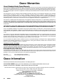
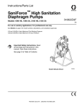
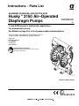
Huskyt2150 Air–Operated
Diaphragm Pumps
308368ZAD
EN
2–inch AODD pump for fluid transfer applications.
For professional use only.
See Models on page 2 for a list of pump models and descriptions.
120 psi (0.8 MPa, 8 bar) Maximum Fluid Working Pressure
120 psi (0.8 MPa, 8 bar) Maximum Air Input Pressure
Patent No.
CN ZL94102643.4
FR 9408894
JA 3517270
US 5,368,452
Important Safety Instructions
Read all warnings and instructions in the manual.
Save these instructions.
03940B
Aluminum Model Shown
Table of Contents
Models . . . . . . . . . . . . . . . . . . . . . . . . . . . . . . . . . . . . . . . . 2
Safety Warnings . . . . . . . . . . . . . . . . . . . . . . . . . . . . . . 3
Installation . . . . . . . . . . . . . . . . . . . . . . . . . . . . . . . . . . . . . 5
Operation . . . . . . . . . . . . . . . . . . . . . . . . . . . . . . . . . . . . 10
Maintenance . . . . . . . . . . . . . . . . . . . . . . . . . . . . . . . . . . 11
Troubleshooting . . . . . . . . . . . . . . . . . . . . . . . . . . . . . . . 12
Service
Repairing the Air Valve . . . . . . . . . . . . . . . . . . . . . . 13
Ball Check Valve Repair . . . . . . . . . . . . . . . . . . . . . 16
Diaphragm Repair . . . . . . . . . . . . . . . . . . . . . . . . . . 17
Bearing and Air Gasket Removal . . . . . . . . . . . . . 20
Pump Matrix . . . . . . . . . . . . . . . . . . . . . . . . . . . . . . . . . .
Repair Kit Matrix . . . . . . . . . . . . . . . . . . . . . . . . . . . . . .
Parts . . . . . . . . . . . . . . . . . . . . . . . . . . . . . . . . . . . . . . . .
Torque Sequence . . . . . . . . . . . . . . . . . . . . . . . . . . . .
Dimensions . . . . . . . . . . . . . . . . . . . . . . . . . . . . . . . . . . .
Technical Data . . . . . . . . . . . . . . . . . . . . . . . . . . . . . . . .
Performance Chart . . . . . . . . . . . . . . . . . . . . . . . . . . . .
Graco Warranties . . . . . . . . . . . . . . . . . . . . . . . . . . . .
Graco Information . . . . . . . . . . . . . . . . . . . . . . . . . . . . .
Models
Model No.
Description
*DF3______
Aluminum Pumps
*DG3______
Aluminum Pumps, Remote
*DFH______
Aluminum Extended Pump
*DGH______
Aluminum Extended Pump, Remote
*DF4______
Stainless Steel Pumps
*DG4______
Stainless Steel Pumps, Remote
*DF6______
Ductile Iron Pumps
*DG6______
Ductile Iron Pumps, Remote
*DFC______
Aluminum BSPT Pumps
*DGC______
Aluminum BSPT Pumps, Remote
*DFD______
Stainless Steel BSPT Pumps
*DGD______
Stainless Steel BSPT Pumps, Remote
*DFF______
Ductile Iron BSPT Pumps
*DGF______
Ductile Iron BSPT Pumps, Remote
*DFG______
Aluminum BSPT Extended Pump
*DGG______
Aluminum BSPT Extended Pump, Remote
*DV4______
Stainless Steel Plus Pumps
*DVD______
Stainless Steel BSPT Plus Pumps
232503
Private–Label Aluminum 2150 Pump (See page 22.)
24B782
Aluminum Pump with overmolded diaphragms
24B783
Stainless Steel Plus Pump with overmolded diaphragms
24B801
Stainless Steel Pump with overmolded diaphragms
24G413
Aluminum BSPT with overmolded diaphragms
24J360
Aluminum Pump with overmolded diaphragms
*NOTE: Refer to the Pump Matrix on page 22 to determine the Model No. of your pump.
NOTE: Plus Models include stainless steel center sections.
2
308368
22
23
24
29
30
32
33
34
34
Symbols
Warning Symbol
Caution Symbol
WARNING
CAUTION
This symbol alerts you to the possibility of serious
injury or death if you do not follow the instructions.
This symbol alerts you to the possibility of damage to
or destruction of equipment if you do not follow the
instructions.
WARNING
EQUIPMENT MISUSE HAZARD
Any misuse of the equipment or accessories, such as overpressurizing, modifying parts, using
incompatible chemicals and fluids, or using worn or damaged parts, can cause them to rupture and
result in splashing in the eyes or on the skin, other serious injury, or fire, explosion or property damage.
D This equipment is for professional use only. Observe all warnings. Read and understand all
instruction manuals, warning labels, and tags before operating the equipment.
D Never alter or modify any part of this equipment; doing so could cause it to malfunction. Use only
genuine Graco parts and accessories.
D Check all equipment regularly and repair or replace worn or damaged parts immediately.
D Never exceed the recommended working pressure or the maximum air inlet pressure stated on
your pump or in the Technical Data on page 32.
D Do not exceed the maximum working pressure of the lowest rated component in your system.
This equipment has a 120 psi (0.8 MPa, 8 bar) maximum working pressure at 120 psi
(0.8 MPa, 8 bar) maximum incoming air pressure.
D Be sure that all fluids and solvents used are chemically compatible with the wetted parts shown in
the Technical Data on page 32. Always read the manufacturer’s literature before using fluid or
solvent in the pump.
D Never move or lift a pump under pressure. If dropped, the fluid section may rupture. Always
follow the Pressure Relief Procedure on page 10 before moving or lifting the pump. The pump
is very heavy. If it must be moved, have two people lift the pump by grasping the outlet manifold
securely.
308368
3
WARNING
HAZARDOUS FLUIDS
Improper handling of hazardous fluids or inhaling toxic vapors can cause extremely serious injury,
even death, due to splashing in the eyes, ingestion, or bodily contamination. Observe all the following precautions when handling known or potentially hazardous fluids.
D Know what fluid you are pumping and its specific hazards. Take precautions to avoid a toxic fluid
spill.
D Always wear appropriate clothing and equipment, such as eye protection and breathing apparatus, to protect yourself.
D Store hazardous fluid in an appropriate, approved container. Dispose of it according to all Local,
State and Federal guidelines for hazardous fluids.
D Secure the fluid outlet hose tightly into the receiving container to prevent it from coming loose
and improperly draining the fluid.
D Pipe and dispose of the exhaust air safely, away from people, animals, and food handling areas.
If the diaphragm fails, the fluid is exhausted along with the air. See Air Exhaust Ventilation on
page 9.
FIRE AND EXPLOSION HAZARD
Static electricity is created by the flow of fluid through the pump and hose. If the equipment is not
properly grounded, sparking may occur. Sparks can ignite fumes from solvents and the fluid being
pumped, dust particles and other flammable substances, whether you are pumping indoors or outdoors, and can cause a fire or explosion and serious injury and property damage.
D To reduce the risk of static sparking, ground the pump and all other equipment used or located in
the work area. Check your local electrical code for detailed grounding instructions for your area
and type of equipment. Refer to Grounding on page 5.
D If you experience any static sparking or even a slight shock while using this equipment, stop
pumping immediately. Check the entire system for proper grounding. Do not use the system
again until the problem has been identified and corrected.
D Pipe and dispose of the exhaust air safely, away from all sources of ignition. If the diaphragm
fails, the fluid is exhausted along with the air. See Air Exhaust Ventilation on page 9.
D Do not smoke in the work area. Do not operate the equipment near a source of ignition or an
open flame, such as a pilot light.
HALOGENATED HYDROCARBON HAZARD
Never use 1,1,1–trichloroethane, methylene chloride, other halogenated hydrocarbon solvents or
fluids containing such solvents in Aluminum Pumps. Such use could result in a serious chemical
reaction, with the possibility of explosion, which could cause death, serious injury and/or substantial
property damage.
Consult your fluid suppliers to ensure that the fluids used are compatible with aluminum parts.
4
308368
Installation
General Information
D The Typical Installation shown in Fig. 2 is only a
guide for selecting and installing system components. Contact your Graco distributor or Graco
Technical Assistance (see back page) for assistance in planning a system to suit your needs.
D Always use Genuine Graco Parts and Accessories.
D Reference numbers and letters in parentheses refer
to the callouts in the figures and the parts lists on
pages 24 to 25.
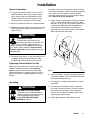
To reduce the risk of static sparking, ground the pump
and all other equipment used or located in the pumping
area. Check your local electrical code for detailed
grounding instructions for your area and type of equipment. Ground all of this equipment:
D Pump: Connect a ground wire and clamp as shown
in Fig. 1. Loosen the grounding screw (W). Insert
one end of a 12 ga (1.5 mm@) minimum ground wire
(Y) behind the grounding screw and tighten the
screw securely. Connect the clamp end of the
ground wire to a true earth ground. Order Part No.
222011 Ground Wire and Clamp.
WARNING
HAZARDOUS FLUIDS
To reduce the risk of serious injury,
splashing in the eyes or on the skin, and
toxic fluid spills, never move or lift a
pump under pressure. If dropped, the fluid section
may rupture. Always follow the Pressure Relief
Procedure Warning on page 10 before moving or
lifting the pump.
Y
D The pump is very heavy. If it must be moved, have
two people lift the pump by grasping the outlet
manifold (103) securely. See Fig. 3 on page 8.
Tightening Screws Before First Use
W
Before using the pump for the first time, check and
retorque all external fasteners. See Torque Sequence, page 29. After the first day of operation,
retorque the fasteners. Although pump use varies, a
general guideline is to retorque fasteners every two
months.
Fig. 1
Grounding
D Air compressor: Follow the manufacturer’s recommendations.
WARNING
FIRE AND EXPLOSION HAZARD
This pump must be grounded. Before
operating the pump, ground the system
as explained below. Also, read the
section FIRE AND EXPLOSION
HAZARD, on page 4.
02646B
D Air and fluid hoses: Use only grounded hoses with
a maximum of 500 ft (150 m) combined hose length
to ensure grounding continuity.
D All solvent pails used when flushing: Follow the
local code. Use only metal pails, which are conductive. Do not place the pail on a non-conductive
surface, such as paper or cardboard, which interrupts the grounding continuity.
D Fluid supply container: Follow the local code.
308368
5
Installation
Mountings
CAUTION
The pump exhaust air may contain contaminants.
Ventilate to a remote area if the contaminants
could affect your fluid supply. See Air Exhaust
Ventilation on page 9.
D Be sure the mounting surface can support the
weight of the pump, hoses, and accessories, as
well as the stress caused during operation.
D For all mountings, be sure the pump is bolted
directly to the mounting surface.
D For ease of operation and service, mount the pump
so the air valve cover (2), air inlet, and fluid inlet
and outlet ports are easily accessible.
b. Locate one bleed-type master air valve (B)
close to the pump and use it to relieve trapped
air. See the WARNING above. Locate the
other master air valve (E) upstream from all air
line accessories and use it to isolate them
during cleaning and repair.
c.
The air line filter (F) removes harmful dirt and
moisture from the compressed air supply.
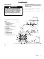
2. Install a grounded, flexible air hose (A) between
the accessories and the 1/2 npt(f) pump air inlet
(N). See Fig. 2. Use a minimum 1/2” (13 mm) ID
air hose. Screw an air line quick disconnect coupler (D) onto the end of the air hose (A), and screw
the mating fitting into the pump air inlet snugly. Do
not connect the coupler (D) to the fitting until you
are ready to operate the pump.
Installation of Remote Pilot Air Lines
D Rubber Foot Mounting Kit 236452 is available to
reduce noise and vibration during operation.
1. Refer to Parts Drawings. Connect air line to pump
as in preceding steps.
Air Line
2. Connect 1/4 in. O.D. tubing to push type connectors (14) on air motor of pump.
WARNING
A bleed-type master air valve (B) is required in
your system to relieve air trapped between this
valve and the pump. Trapped air can cause the
pump to cycle unexpectedly, which could result in
serious injury, including splashing in the eyes or on
the skin, injury from moving parts, or contamination
from hazardous fluids. See Fig. 2.
1. Install the air line accessories as shown in Fig. 2.
Mount these accessories on the wall or on a
bracket. Be sure the air line supplying the accessories is grounded.
a. Install an air regulator (C) and gauge to control
the fluid pressure. The fluid outlet pressure will
be the same as the setting of the air regulator.
NOTE: by replacing the push type connectors, other
sizes or types of fittings may be used. The new fittings
will require 1/8 in. npt threads.
3. Connect remaining ends of tubes to external air
signal, such as Graco’s Cycleflo (P/N 195264) or
Cycleflo II (P/N 195265) controllers.
Fluid Suction Line
1. Use grounded fluid hoses (G). The pump fluid
inlet (R) is 2” npt(f). Screw the fluid fitting into the
pump inlet securely.
2. If the fluid inlet pressure to the pump is more than
25% of the outlet working pressure, the ball check
valves will not close fast enough, resulting in
inefficient pump operation.
3. At inlet fluid pressures greater than 15 psi
(0.1 MPa, 1 bar), diaphragm life will be shortened.
4. See the Technical Data on page 32 for maximum
suction lift (wet and dry).
6
308368
Installation
1. Use grounded fluid hoses (L). The pump fluid
outlet (S) is 2” npt(f). Screw the fluid fitting into the
pump outlet securely.
Fluid Outlet Line
WARNING
A fluid drain valve (J) is required to relieve pressure in the hose if it is plugged. The drain valve
reduces the risk of serious injury, including splashing in the eyes or on the skin, or contamination
from hazardous fluids when relieving pressure.
Install the valve close to the pump fluid outlet. See
Fig. 2.
2. Install a fluid drain valve (J) near the fluid outlet.
See the WARNING above.
3. Install a shutoff valve (K) in the fluid outlet line.
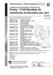
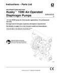
FLOOR-MOUNT TYPICAL INSTALLATION
B
KEY
A Air supply hose
B Bleed-type master air valve
(required for pump)
C Air regulator
D Air line quick disconnect
E Master air valve (for accessories)
F Air line filter
G Fluid suction hose
H Fluid supply
J Fluid drain valve (required)
K Fluid shutoff valve
L Fluid hose
N 1/2 npt(f) air inlet port
R 2 npt(f) fluid inlet port
S 2 npt(f) fluid outlet port
Y Ground wire (required; see page 5
for installation instructions)
C
F
E
A
K
S
L
D
N
J
Y
H
R
G
03943B
Fig. 2
308368
7
Installation
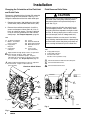
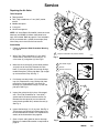
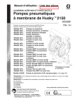
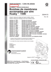
Changing the Orientation of the Fluid Inlet
and Outlet Ports
The pump is shipped with the fluid inlet (R) and outlet
(S) ports facing the same direction. See Fig. 3. To
change the orientation of the inlet and/or outlet port:
Fluid Pressure Relief Valve
CAUTION
1. Remove the screws (106) holding the inlet (102)
and/or outlet (103) manifold to the covers (101).
Some systems may require installation of a pressure relief valve at the pump outlet to prevent
overpressurization and rupture of the pump or
hose. See Fig. 4.
2. Reverse the manifold and reattach. Install the
screws and torque to 120 to 150 in-lb (14 to 17
NSm). on aluminum pumps. Torque to 190–220
in–lb (22–25 NSm) on ductile iron and stainless
steel pumps. See Torque Sequence, page 29.
Thermal expansion of fluid in the outlet line can
cause overpressurization. This can occur when
using long fluid lines exposed to sunlight or ambient heat, or when pumping from a cool to a warm
area (for example, from an underground tank).
KEY
N 1/2 npt(f) air inlet port
P Muffler. Air exhaust
port is 3/4 npt(f).
R 2 npt(f) fluid
inlet port
S 2 npt(f) fluid
outlet port
1
2
101
102
103
106
Covers
Fluid inlet manifold
Fluid outlet manifold
Manifold and cover
screws
112 Cover screws
(top and bottom)
Apply medium-strength (blue) LoctiteR or equivalent
to the threads. Torque to 120 to 150 in-lb
(14 to 17 NSm) on Aluminum pumps. Torque to
190–220 in–lb (22–25 NSm) on ductile iron and stainless steel pumps. See Torque Sequence, page 29.
Apply medium-strength (blue) LoctiteR or equivalent
to the threads. Torque to 190 to 220 in-lb
(22 to 25 NSm).
Aluminum Model Shown
Overpressurization can also occur if the Husky
pump is being used to feed fluid to a piston pump,
and the intake valve of the piston pump does not
close, causing fluid to back up in the outlet line.
KEY
R 2 npt(f) fluid inlet port
S 2 npt(f) fluid outlet port
V Pressure relief valve
Part No. 112119 (stainless steel)
1
Install valve between fluid inlet and outlet ports.
2
Connect fluid inlet line here.
3
Connect fluid outlet line here.
103
S
3
S
N
106
1
106
V
1
2
2
101
112
2
P
R
R
Fig. 4
102
03940B
Fig. 3
8
308368
03941B
Installation
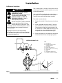
Air Exhaust Ventilation
The air exhaust port is 3/4 npt(f). Do not restrict the air
exhaust port. Excessive exhaust restriction can cause
erratic pump operation.
WARNING
FIRE AND EXPLOSION HAZARD;
HAZARDOUS FLUIDS
Be sure to read and follow the warnings
and precautions regarding HAZARDOUS FLUIDS, and FIRE OR
EXPLOSION HAZARD on page 4,
before operating this pump.
If the muffler (P) is installed directly to the air exhaust
port, apply PTFE thread tape or anti–seize thread
lubricant to the muffler threads before assembly.
To provide a remote exhaust:
1. Remove the muffler (P) from the pump air exhaust
port.
Be sure the system is properly ventilated
for your type of installation. You must
vent the exhaust to a safe place, away
from people, animals, food handling areas, and all
sources of ignition when pumping flammable or
hazardous fluids.
2. Install a grounded air exhaust hose (T) and connect the muffler (P) to the other end of the hose.
The minimum size for the air exhaust hose is 3/4
in. (19 mm) ID. If a hose longer than 15 ft (4.57 m)
is required, use a larger diameter hose. Avoid
sharp bends or kinks in the hose. See Fig. 5.
Diaphragm failure will cause the fluid being
pumped to exhaust with the air. Place an appropriate container at the end of the air exhaust line to
catch the fluid. See Fig. 5.
3. Place a container (U) at the end of the air exhaust
line to catch fluid in case a diaphragm ruptures.
VENTING EXHAUST AIR
KEY
E
F
C
A
B
B
A
C
D
E
F
P
T
U
Air supply line
Bleed-type master air valve
(required for pump)
Air regulator
Air line quick disconnect
Master air valve (for accessories)
Air line filter
Muffler
Grounded air exhaust hose
Container for remote air exhaust
D
T
U
P
03942
Fig. 5
308368
9
Operation
Flush the Pump Before First Use
Operation of Remote Piloted Pumps
The pump was tested with lightweight oil, which is left
in the fluid passages to protect parts. To avoid contaminating your fluid with oil, flush the pump with a compatible solvent before using the equipment. Follow the
steps under Starting and Adjusting the Pump.
1. Fig. 2 and Parts Drawings. Follow preceding steps
1 through 7 of Starting and Adjusting Pump.
Starting and Adjusting the Pump
WARNING
HAZARDOUS FLUIDS
To reduce the risk of serious injury,
splashing in the eyes or on the skin, and
toxic fluid spills, never move or lift a
pump under pressure. If dropped, the fluid section
may rupture. Always follow the Pressure Relief
Procedure Warning at right before moving or
lifting the pump.
1. Be sure the pump is properly grounded. Refer to
Grounding on page 5.
2. Check all fittings to be sure they are tight. Be sure
to use a compatible liquid thread sealant on all
male threads. Tighten the fluid inlet and outlet
fittings securely.
3. Place the suction tube (if used) in the fluid to be
pumped.
NOTE: If the fluid inlet pressure to the pump is more
than 25% of the outlet working pressure, the ball check
valves will not close fast enough, resulting in inefficient
pump operation.
4. Place the end of the fluid hose (L) into an appropriate container.
5. Close the fluid drain valve (J). See Fig. 2.
6. With the pump air regulator (C) closed, open all
bleed-type master air valves (B, E).
7. If the fluid hose has a dispensing device, hold it
open while continuing with the following step.
8. Slowly open the air regulator (C) until the pump
starts to cycle. Allow the pump to cycle slowly until
all air is pushed out of the lines and the pump is
primed.
If you are flushing, run the pump long enough to
thoroughly clean the pump and hoses. Close the
air regulator. Remove the suction tube from the
solvent and place it in the fluid to be pumped.
10
308368
2. Open air regulator (C).
WARNING
The pump may cycle once before the external signal is applied. Injury is possible. If pump cycles,
wait until end before proceeding.
3. Pump will operate when air pressure is alternately
applied and relieved to push type connectors (14).
NOTE: Leaving air pressure applied to the air motor for
extended periods when the pump is not running may
shorten the diaphragm life. Using a 3-way solenoid
valve to automatically relieve the pressure on the air
motor when the metering cycle is complete prevents
this from occurring.
Pump Shutdown
At the end of the work shift and before checking,
adjusting, cleaning or repairing the system, follow the
Pressure Relief Procedure below.
Pressure Relief Procedure
WARNING
To reduce the risk of serious injury, including
splashing fluid in the eyes or on the skin, follow this
procedure when this manual instructs you to
relieve pressure, when you shut off the pump, and
before checking, adjusting, cleaning, moving, or
repairing any system equipment.
1. Shut off the air to the pump.
2. Open the dispensing valve, if used.
3. Open the fluid drain valve to relieve all fluid pressure, having a container ready to catch the drainage.
Maintenance
Lubrication
Tightening Threaded Connections
The air valve is designed to operate unlubricated,
however if lubrication is desired, every 500 hours of
operation (or monthly) remove the hose from the pump
air inlet and add two drops of machine oil to the air
inlet.
Before each use, check all hoses for wear or damage,
and replace as necessary. Check to be sure all
threaded connections are tight and leak-free. Check
fasteners. Tighten or retorque as necessary. Although
pump use varies, a general guideline is to retorque
fasteners every two months. See Torque Sequence,
page 29.
CAUTION
Do not over-lubricate the pump. Oil is exhausted
through the muffler, which could contaminate your
fluid supply or other equipment. Excessive lubrication can also cause the pump to malfunction.
Preventive Maintenance Schedule
Establish a preventive maintenance schedule, based
on the pump’s service history. This is especially important for prevention of spills or leakage due to diaphragm failure.
Flushing and Storage
Flush the pump often enough to prevent the fluid you
are pumping from drying or freezing in the pump and
damaging it. Always flush the pump and follow the
Pressure Relief Procedure Warning on page 10
before storing it for any length of time. Use a compatible solvent.
308368
11
Troubleshooting
WARNING
To reduce the risk of serious injury, including splashing fluid in the eyes or on the skin, follow the Pressure
Relief Procedure on page 10 when this manual instructs you to relieve pressure, when you shut off the pump,
and before checking, adjusting, cleaning, moving, or repairing any system equipment.
NOTE: Check all possible problems and causes before disassembling the pump.
PROBLEM
CAUSE
SOLUTION
Pump cycles at stall or fails to hold pressure at stall.
Worn check valve balls (301), seats
(201) or o-rings (202).
Replace. See page 16.
Pump will not cycle, or cycles once and
stops.
Air valve is stuck or dirty.
Disassemble and clean air valve. See
pages 13 to 14. Use filtered air.
Check valve ball (301) severely worn
and wedged in seat (201) or manifold
(102 or 103).
Replace ball and seat. See page 16.
Check valve ball (301) is wedged into
seat (201), due to overpressurization.
Install Pressure Relief Valve
(see page 8).
Dispensing valve clogged.
Relieve pressure and clear valve.
Clogged suction line.
Inspect; clear.
Sticky or leaking check valve balls
(301).
Clean or replace. See page 16.
Diaphragm ruptured.
Replace. See pages 17 to 19.
Restricted exhaust.
Remove restriction.
Suction line is loose.
Tighten.
Diaphragm ruptured.
Replace. See pages 17 to 19.
Loose inlet manifold (102), damaged
seal between manifold and seat (201),
or damaged o-rings (202).
Tighten manifold bolts (106) or replace
seats (201) or o-rings (202). See page
16.
Loose diaphragm shaft bolt (107).
Tighten or replace. See pages 17 to 19.
Damaged o-ring (108).
Replace. See pages 17 to 19.
Diaphragm ruptured.
Replace. See pages 17 to 19.
Loose diaphragm shaft bolt (107).
Tighten or replace. See pages 17 to 19.
Damaged o-ring (108).
Replace. See pages 17 to 19.
Worn air valve block (7), o-ring (6),
plate (8), pilot block (18), u-cups (10), or
pilot pin o-rings (17).
Repair or replace. See pages 13 to 14.
Worn shaft seals (402).
Replace. See pages 17 to 19.
Air valve cover (2) or air valve cover
screws (3) are loose.
Tighten screws. See page 14.
Air valve gasket (4) or air cover gasket
(22) is damaged.
Inspect; replace. See pages 13 to 14,
20 to 21.
Air cover screws (3) are loose.
Tighten screws. See pages 20 to 21.
Loose manifolds (102, 103), damaged
seal between manifold and seat (201),
or damaged o-rings (202).
Tighten manifold bolts (106) or replace
seats (201) or o-rings (202). See page
16.
Pump operates erratically.
Air bubbles in fluid.
Fluid in exhaust air.
Pump exhausts excessive air at stall.
Pump leaks air externally.
Pump leaks fluid externally from ball
check valves.
12
308368
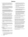
Service
Repairing the Air Valve
3
2
Tools Required
2
D Torque wrench
4{H
D Torx (T20) screwdriver or 7 mm (9/32”) socket
wrench
D Needle-nose pliers
D O-ring pick
D Lithium base grease
NOTE: Air Valve Repair Kits 236273 (aluminum center
housings) and 255061 (stainless steel center housings) are available. Refer to page 24. Parts included in
the kit are marked with a symbol, for example (4{H).
Use all the parts in the kit for the best results.
Disassembly
1. Follow the Pressure Relief Procedure Warning
on page 10.
2
2. With a Torx (T20) screwdriver or 7 mm (9/32”)
socket wrench, remove the six screws (3), air
valve cover (2), and gasket (4). See Fig. 6.
3. Move the valve carriage (5) to the center position
and pull it out of the cavity. Remove the valve
block (7) and o-ring (6) from the carriage. Using a
needle-nose pliers, pull the pilot block (18) straight
up and out of the cavity. See Fig. 7.
Torque to 50 to 60 in–lb (5.6 to 6.8 NSm).
03944
Fig. 6
1
See Detail at right.
2
Grease.
3
Grease lower face.
4. Pull the two actuator pistons (11) out of the bearings (12). Remove the u-cup packings (10) from
the pistons. Pull the pilot pins (16) out of the
bearings (15). Remove the o-rings (17) from the
pilot pins. See Fig. 8.
5
2
H{6
3
H{7
H{18 3
5
5. Inspect the valve plate (8) in place. If damaged,
use a Torx (T20) screwdriver or 7 mm (9/32”)
socket wrench to remove the three screws (3).
Remove the valve plate (8) and, on aluminum
center housing models only, remove the seal (9).
See Fig. 9.
11
6. Inspect the bearings (12, 15) in place. See Fig. 8.
The bearings are tapered and, if damaged, must
be removed from the outside. This requires disassembly of the fluid section. See page 20.
7. Clean all parts and inspect for wear or damage.
Replace as needed. Reassemble as explained on
page 14.
1
16
03945
Fig. 7
308368
13
Service
Reassembly
1
Insert narrow end first.
2
Grease.
3
Install with lips facing narrow end of piston (11).
4
Insert wide end first.
1. If you removed the bearings (12, 15), install new
ones as explained on page 20. Reassemble the
fluid section.
2. On aluminum center housing models, install the
valve plate seal (9{) into the groove at the bottom
of the valve cavity. The rounded side of the seal
must face down into the groove. See Fig. 9.
10{H
2
11
4
3
12
3. Install the valve plate (8H) in the cavity. On aluminum center housing models, the plate is reversible,
so either side can face up. Install the three screws
(3), using a Torx (T20) screwdriver or 7 mm (9/32”)
socket wrench. Tighten until the screws bottom out
on the housing. See Fig. 9.
4. Install an o-ring (17{H) on each pilot pin (16).
Grease the pins and o-rings. Insert the pins into
the bearings (15), narrow end first. See Fig. 8.
2
Fig. 8
17{
15 16
1
03946
6. Lubricate the u-cup packings (10{H) and actuator
pistons (11). Insert the actuator pistons in the
bearings (12), wide end first. Leave the narrow
end of the pistons exposed. See Fig. 8.
1 Rounded side must face down (aluminum center
2
housing models only).
Tighten screws until they bottom
out on the housing.
3
5. Install a u-cup packing (10{H) on each actuator
piston (11), so the lips of the packings face the
narrow end of the pistons. See Fig. 8.
2
8H
9{
7. Grease the lower face of the pilot block (18{H) and
install so its tabs snap into the grooves on the
ends of the pilot pins (16). See Fig. 7.
1
8. Grease the o-ring (6{H) and install it in the valve
block (7{H). Push the block onto the valve carriage
(5). Grease the lower face of the valve block. See
Fig. 7.
9. Install the valve carriage (5) so its tabs slip into the
grooves on the narrow end of the actuator pistons
(11). See Fig. 7.
03947
Fig. 9
14
308368
10. Align the valve gasket (4{H) and cover (2) with the
six holes in the center housing (1). Secure with six
screws (3), using a Torx (T20) screwdriver or 7
mm (9/32”) socket wrench. Torque to 50 to 60 in-lb
(5.6 to 6.8 NSm). See Fig. 6.
Notes
308368
15
Service
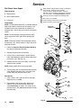
Ball Check Valve Repair
1
Tools Required
D Torque wrench
Apply medium-strength (blue) LoctiteR or equivalent
to the threads. Torque to 120 to 150 in-lb
(14 to 17 NSm) on aluminum pumps. Torque to
190–220 in–lb (22–25 NSm) on ductile iron and stainless steel pumps. See Torque Sequence, page 29.
D 10 mm socket wrench
2
Arrow (A) must point toward outlet manifold (103).
3
D O-ring pick
4
Not used on some models.
Beveled seating surface must face ball (301).
5
Used on stainless steel model only.
Disassembly
NOTE: A Fluid Section Repair Kit is available. Refer to
page 23 to order the correct kit for your pump. Parts
included in the kit are marked with an asterisk, for
example (201*). Use all the parts in the kit for the best
results.
Z117
Extension
Models Only
103
NOTE: To ensure proper seating of the balls (301),
always replace the seats (201) when replacing the
balls.
106
1
*301
*201
*202
NOTE: (Extension Version) To ensure proper sealing
of extension (115), always replace o–rings (116) when
replacing the balls.
Z115
103
1. Follow the Pressure Relief Procedure Warning
on page 10. Disconnect all hoses.
*301
2. Remove the pump from its mounting.
4
*201
3
*202
Z116
101
TI2233A
3. Using a 10 mm socket wrench, remove the four
bolts (106) holding the outlet manifold (103) to the
fluid covers (101). See Fig. 10.
101
4. Remove the seats (201), balls (301), and o-rings
(202) from the manifold.
NOTE: Some models do not use o-rings (202).
113
5. Turn the pump over and remove the inlet manifold
(102). Remove the seats (201), balls (301), and
o-rings (202) from the fluid covers (101).
A
5
2
Reassembly
301*
1. Clean all parts and inspect for wear or damage.
Replace parts as needed.
2. Reassemble in the reverse order, following all
notes in Fig. 10. Be sure the ball checks are
assembled exactly as shown. The arrows (A) on
the fluid covers (101) must point toward the outlet
manifold (103).
201*
4
202*
3
102
106
Fig. 10
16
308368
1
TI0352B
Service
Disassembly
NOTE: A Fluid Section Repair Kit is available. Refer to
page 23 to order the correct kit for your pump. Parts
included in the kit are marked with an asterisk, for
example (401*). Use all the parts in the kit for the best
results.
Diaphragm Repair
Tools Required
D Torque wrench
D 10 mm socket wrench
D 13 mm socket wrench
D 15 mm socket wrench (aluminum models) or
1” socket wrench (stainless steel models)
D 19 mm open–end wrench
1. Follow the Pressure Relief Procedure Warning
on page 10.
2. Remove the manifolds and disassemble the ball
check valves as explained on page 16.
3. Using 10 and 13 mm socket wrenches, remove the
screws (106 and 112) holding the fluid covers
(101) to the air covers (23). Pull the fluid covers
(101) off the pump. See Fig. 11.
D O-ring pick
D Lithium-base grease
1
2
Apply medium-strength (blue) LoctiteR or equivalent to the threads.
You must torque the eight long screws (112) first, then the short
screws (106). Torque to 190 to 220 in-lb (22 to 25 NSm). See Torque
Sequence, page 29.
Arrow (A) must point toward air valve (B).
B
23
101
A
2
106
1
112
1
03949B
Fig. 11
308368
17
Service
4. Loosen but do not remove the diaphragm shaft
bolts (107), using a 15 mm socket wrench (1” on
stainless steel models) on both bolts. NOTE: This
step does not apply to pumps with overmolded
diaphragms.
5. Unscrew one bolt from the diaphragm shaft (24)
and remove the o-ring (108), fluid side diaphragm
plate (105), PTFE diaphragm (403, used on PTFE
Models only), diaphragm (401), and air side diaphragm plate (104). See Fig. 12.
c.
d. Install the diaphragm (401*) on the bolt. Make
certain the side marked AIR SIDE faces the
center housing (1).
e. Install the air side diaphragm plate (104) so
the recessed side faces the diaphragm (401).
f.
For overmolded diaphragms: Grip both diaphragms securely around the outer edge and
rotate counterclockwise. One diaphragm assembly
will come free and the other will remain attached to
the shaft. Remove the freed diaphragm and air
side plate.
6. Pull the other diaphragm assembly and the diaphragm shaft (24) out of the center housing (1).
Hold the shaft flats with a 19 mm open–end
wrench, and remove the bolt (107) from the shaft.
Disassemble the remaining diaphragm assembly.
For overmolded diaphragms: Pull the other diaphragm assembly and the diaphragm shaft (24)
out of the center housing (1). Hold the shaft flats
with a 19 mm open–end wrench and remove the
diaphragm and air side plate from the shaft.
7. Inspect the diaphragm shaft (24) for wear or
scratches. If it is damaged, inspect the bearings
(19) in place. If the bearings are damaged, refer to
page 20.
8. Reach into the center housing (1) with an o-ring
pick and hook the u-cup packings (402), then pull
them out of the housing. This can be done with the
bearings (19) in place.
9. Clean all parts and inspect for wear or damage.
Replace parts as needed.
Reassembly
1. Install the shaft u-cup packings (402*) so the lips
face out of the housing (1). Lubricate the packings. See Fig. 12.
2. Install the diaphragm assembly on one end of the
shaft (24) as follows. For pumps with overmolded
diaphragms, go directly to step g.
a. Install the o-ring (108*) on the shaft bolt (107).
b. Install the fluid side diaphragm plate (105) on
the bolt so the rounded side faces in, toward
the diaphragm (401).
18
308368
On PTFE Models only, install the PTFE diaphragm (403*). Make certain the side marked
AIR SIDE faces the center housing (1).
Apply medium-strength (blue) LoctiteR or
equivalent to the bolt (107) threads. Screw the
bolt into the shaft (24) hand tight.
g. For overmolded diaphragms: Assemble the air
side plate (104) onto the diaphragm (403). The
wide, radiused side of the plate must face the
diaphragm. Apply medium–strength (blue)
Loctite or equivalent to the threads of the
diaphragm assembly. Screw the assembly into
the shaft (24) hand tight.
3. Grease the length and ends of the diaphragm shaft
(24), and slide it through the housing (1).
4. Assemble the other diaphragm assembly to the
shaft as explained in step 2.
5. Hold one shaft bolt (107) with a wrench and torque
the other bolt to 20 to 25 ft-lb (27 to 34 NSm) at
100 rpm maximum. NOTE: This step does not
apply to pumps with overmolded diaphragms.
6. Align the fluid covers (101) and the center housing
(1) so the arrows (A) on the covers face the same
direction as the air valve (B). Secure the covers
with the screws (106 and 112), handtight. Install
the longer screws (112) in the top and bottom
holes of the covers. See Fig. 11.
7. First, torque the longer screws (112) oppositely
and evenly to 190 to 220 in-lb (22 to 25 NSm),
using a 13 mm socket wrench. Then torque the
shorter screws (106), using a 10 mm socket
wrench. See Torque Sequence, page 29.
8. Reassemble the ball check valves and manifolds
as explained on page 16.
Service
2
5
1
24
4
104
7
19
105
402*
107
403*
401*
3
3
1
1
6
03981A
Cutaway View, with Diaphragms in Place
03982A
Cutaway View, with Diaphragms Removed
24
4
104
7
401*
3
403*
3
6
105
2
108*
1
107
24
5
4
1
Lips face out of housing (1).
2
Rounded side faces diaphragm (401).
3
Air Side must face center housing (1).
4
Grease.
5
6
Apply medium-strength (blue) LoctiteR or equivalent.
Torque to 20 to 25 ft-lb (27 to 34 NSm) at 100 rpm maximum.
Used on Models with PTFE diaphragms only.
7
Recessed side faces diaphragm (401).
03950B
Fig. 12
308368
19
Service
Bearing and Air Gasket Removal
Tools Required
D Torque wrench
D 10 mm socket wrench
D Bearing puller
D O-ring pick
D Press, or block and mallet
Disassembly
NOTE: Do not remove undamaged bearings.
1. Follow the Pressure Relief Procedure Warning
on page 10.
2. Remove the manifolds and disassemble the ball
check valves as explained on page 16.
3. Remove the fluid covers and diaphragm assemblies as explained on page 17.
NOTE: If you are removing only the diaphragm shaft
bearing (19), skip step 4.
4. Disassemble the air valve as explained on
page 13.
5. Using a 10 mm socket wrench, remove the screws
(25) holding the air covers (23) to the center
housing (1). See Fig. 13.
6. Remove the air cover gaskets (22). Always replace
the gaskets with new ones.
7. Use a bearing puller to remove the diaphragm
shaft bearings (19), air valve bearings (12) or pilot
pin bearings (15). Do not remove undamaged
bearings.
8. If you removed the diaphragm shaft bearings (19),
reach into the center housing (1) with an
o-ring pick and hook the u-cup packings (402),
then pull them out of the housing. Inspect the
packings. See Fig. 12.
Reassembly
1. If removed, install the shaft u-cup packings (402*)
so the lips face out of the housing (1).
2. The bearings (19, 12, and 15) are tapered and can
only be installed one way. Insert the bearings into
the center housing (1), tapered end first. Using a
press or a block and rubber mallet, press-fit the
bearing so it is flush with the surface of the center
housing.
3. Reassemble the air valve as explained on
page 14.
4. Align the new air cover gasket (22) so the pilot pin
(16) protruding from the center housing (1) fits
through the proper hole (H) in the gasket.
5. Align the air cover (23) so the pilot pin (16) fits in
the middle hole (M) of the three small holes near
the center of the cover. Install the screws (25),
handtight. See Fig. 13. Using a 10 mm socket
wrench, torque the screws oppositely and evenly
to 120 to 150 in-lb (14 to 17 NSm).
6. Install the diaphragm assemblies and fluid covers
as explained on page 17.
7. Reassemble the ball check valves and manifolds
as explained on page 16.
20
308368
Service
1
Insert bearings tapered end first.
2
Press-fit bearings flush with surface of center housing (1).
3
Apply medium-strength (blue) LoctiteR or equivalent
to the threads. Torque to 120 to 150 in-lb
(14 to 17 NSm).
12
1
16 H
1
1
15
22
M
23
1
2
1
03951
Detail of Air Valve Bearings
25
19
2
3
2
03952B
Fig. 13
308368
21
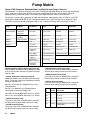
Pump Matrix
Husky 2150 Aluminum, Stainless Steel, and Ductile Iron Pumps, Series A
Your Model No. is marked on the pump’s serial plate. To determine the Model No. of your pump from the following
matrix, select the six digits which describe your pump, working from left to right. The first digit is always D,
designating Husky diaphragm pumps. The remaining five digits define the materials of construction.
For example, a pump with an aluminum air motor and fluid section, polypropylene seats, PTFE balls, and PTFE
diaphragms is Model No. D F 3 9 1 1. To order replacement parts, refer to the part lists on pages 24 and 25.
The digits in the matrix do not correspond to the ref. nos. in the parts drawing and lists on pages 24 and 25.
Diaphragm
Pump
Air Motor
Fluid Section
– Seats
Balls
Diaphragms
232503*
aluminum
aluminum
– TPE
acetal
TPE
D (for all pumps)
F aluminum
1 (not used)
– 1 (not used)
1 (PTFE)
1 (PTFE)
24B782*
G aluminum
(remote)
2 (not used)
– 2 (not used)
2 (acetal)
2 (not used)
24B783*
V SST (standard)
3 (aluminum)
– 3 (316 sst)
3 (not used)
3 (not used)
24B801*
4 (sst)
– 4 (17–4 PH sst)
4 (440C sst)
4 (not used)
24G413*
5 (not used)
– 5 (TPE)
5 (TPE)
5 (TPE)
6 (ductile iron)
– 6 (Santoprener)
6 (Santoprener)
6 (Santoprener)
C (aluminum
BSPT)
– 7 (Buna–N)
7 (Buna–N)
7 (Buna–N)
D (sst BSPT)
– 8 (Fluoroelastomer)
8 (Fluoroelastomer)
8 (Fluoroelastomer)
F (ductile iron
BSPT)
– 9 (Polypropylene)
G (aluminum
BSPT extended)
– G (Geolastr)
G (Geolastr)
G (Geolastr)
H (aluminum
extended)
–
(standard)
246452 Stainless Steel Air Motor Conversion Kit
Use kit 246452 and refer to manual 309643 (included
in kit) to convert from aluminum air motor to stainless
steel air motor.
* 232503, Aluminum 2150 Pump, Series D
Model No. 232503 is a private-label aluminum 2150
pump. This pump is the same as Model No. DF3525
except for the label and:
Ref. Nos. 10 and 402 are 115666 Packing, U–cup,
Fluoroelastomer
Ref. No. 17 is 168518 O–ring, Fluoroelastomer
* 24B783 Stainless Steel Plus Pump
This pump is the same as Model DV4311 except for
the serial plate and parts listed in the chart below.
* 24B801 Stainless Steel Pump
This pump is the same as Model DF4311 except for
the serial plate and parts listed in the chart below.
* 24G413 Aluminum pump
This pump is the same as Model DFC311 except for
the serial plate and parts listed in the chart below.
Use 243492 as the Air Valve Repair Kit
Ref.
No.
Part No.
Description
Qty
Ref. 106 is 112416 SCREW, SST; M10 x 1.5; 30 mm
104
15H811
PLATE, air side; alum.
2
Ref. 112 is 112417 SCREW, SST; M10 x 1.5; 90 mm
105
–––
not used
0
* 24B782 Aluminum Pump
This pump is the same as Model DF3311 except for
the serial plate and parts listed in the chart at right.
107
–––
not used
0
108
–––
not used
0
401
15G746
DIAPHRAGM, HD, overmolded;
PTFE/EPDM
2
* 24J360 Aluminum Pump
This pump is the same as Model DF3321 except for
the serial plate and parts listed in the chart at right.
22
308368
Repair Kit Matrix
For Husky 2150 Aluminum and Stainless Steel Pumps, Series A
Repair Kits may be ordered separately. To repair the air valve, order Part No. 236273 for aluminum center housing
models, or Part No. 255061 for stainless steel housing models (see page 24). Parts included in the Air Valve Repair
Kit are marked with a symbol in the parts list, for example (4{H).
To repair the seats, balls, and diaphragms, select the six digits which describe your pump from the following matrix,
working from left to right. The first digit is always D, and the second digit is always 0 (zero). The remaining four
digits define the materials of construction. Parts included in the kit are marked with an asterisk in the parts list, for
example (201*).
For example, if your pump has polypropylene seats, PTFE balls, and PTFE diaphragms, you need to order Repair
Kit D 0 F 9 1 1. The digits in the matrix do not correspond to the ref. nos. in the parts drawing and lists on
pages 24 and 25.
Diaphragm
Pump
Null
Shaft O-Ring
– Seats
Balls
Diaphragms
D (for all pumps)
0 (for all pumps)
F (PTFE)
– 0 (null)
0 (null)
0 (null)
– 1 (not used)
1 (PTFE)
1 (PTFE)
– 2 (not used)
2 (acetal)
2 (not used)
– 3 (316 sst)
3 (not used)
3 (not used)
– 4 (17–4 PH sst)
4 (440C sst)
4 (not used)
– 5 (TPE)
5 (TPE)
5 (TPE)
– 6 (Santoprener)
6 (Santoprener)
6 (Santoprener)
– 7 (Buna–N)
7 (Buna–N)
7 (Buna–N)
– 8 (Fluoroelastomer)
8 (Fluoroelastomer)
8 (Fluoroelastomer)
G (Geolastr)
G (Geolastr)
– 9 (Polypropylene)
– G (Geolastr)
Part No. 253628: Husky 2150 HD Overmolded PTFE/EPDM Diaphragm Repair Kit.
Part No. 289226: Husky 2150 HD Overmolded PTFE/EPDM Diaphragm Repair Kit,
with new air side diaphragm plates.
Part No. 24F400: Husky 2150 PTFE/Santoprene Backer Diaphragm Repair Kit for Metal Pumps.
Extension Conversion Kit
To convert an existing 2150 Aluminum pump to an extended version, use conversion kit 234019.This kit is for 2 in
(50.8 mm) npt or bspt ported aluminum pumps only. It extends the outlet manifold to match the inlet to outlet distance of a Wilden or ARO aluminum pump.
308368
23
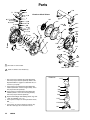
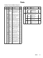
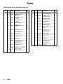
Parts
3
106
2
11 10{H
4{H
H{17
16
H{18
5
3
1
104
6{H
7{H
8H
9{ 1
16
17{H
}14
12
10{H
11 22
20
111
Y110
401*
301*
403* 1
201*
105
202*
1
23
106
25
24
15
*402
103
Aluminum Model Shown
108* 107
19
2
}13
113
112
101
*301
*201
1
202*
102
1
Not used on some models
TI0353B
106
2
Used on stainless steel model only
Z117
Extension
* These parts are included in the Pump Repair Kit,
which may be purchased separately. Refer to the
Repair Kit Matrix on page 23 to determine the correct kit for your pump.
{ These parts are included in Air Valve Repair Kit
236273 (aluminum center housing models), which
may be purchased separately.
J These parts are included in Air Valve Repair Kit
255061 (stainless steel center housing models),
which may be purchased separately..
Y Replacement Danger and Warning labels, tags and
cards are available at no cost.
} These parts are unique to remote piloted air motor,
DG _ _ _ _
Z These parts are used on extension version only.
Ref. No. 106 is qty. 20 on extension version.
103
*301
*201
*202
Z115
Z116
101
TI2233A
24
308368
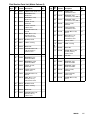
Parts
Air Motor Parts List (Matrix Column 2)
Ref.
Digit No.
Part No.
Description
Qty
Ref.
Digit No.
F
1
188838
HOUSING, center;
1
G
2
188854
COVER, air valve; alum.
1
3
116344
SCREW, mach, hex
flange hd; M5x0.8;12 mm
(0.47 in.)
9
V
4{H
188618
GASKET, cover; foam
1
5
188855
CARRIAGE; aluminum
1
6{H
108730
O-RING; nitrile
7{H
188616
8
9{
Part No.
Description
Qty
Same as F with the following exceptions
1
195921
HOUSING, center;
remote, aluminum
1
23
195919
COVER, air; remote
2
Same as F with the following exceptions
1
15K009
HOUSING, center;
stainless steel
1
1
2
15A735
COVER, air valve;
stainless steel
1
BLOCK, air valve; acetal
1
8H
15H178
1
188615
PLATE, air valve; sst
1
PLATE, air valve;
stainless steel
188617
SEAL, valve plate;bunaN
1
9
–
–
–
23
15A742
COVER, air; stainless
steel
2
10{H
112181
PACKING, u-cup; nitrile
2
11
188612
PISTON, actuator; acetal
2
12
188613
BEARING, piston; acetal
2
13}
104765
PLUG, pipe; headless
2
14}
115671
FITTING, connector;
male
2
15
188611
BEARING, pin; acetal
2
16
188610
PIN, pilot; stainless steel
2
17{H
157628
O-RING; buna-N
2
18{H
188614
BLOCK, pilot; acetal
1
19
188609
BEARING, shaft; acetal
2
20
116343
SCREW, grounding
1
22
188603
GASKET, air cover; foam 2
23
189300
COVER, air; aluminum
2
24
189304
SHAFT, diaphragm; sst
1
25
115643
SCREW; M8x .25; 25
mm
12
308368
25
Parts
Fluid Section Parts List (Matrix Column 3)
Ref.
Digit No.
Part No.
Description
Qty
Ref.
Digit No.
Part No.
Description
Qty
3
101
15A612
COVER, fluid; aluminum
2
4
101
194279
2
102
189302
MANIFOLD, inlet;
aluminum
1
COVER, fluid;
316 stainless steel
102
194280
1
MANIFOLD, outlet;
aluminum
1
MANIFOLD, inlet;
316 stainless steel
103
194281
1
PLATE, air side;
aluminum
2
MANIFOLD, outlet;
316 stainless steel
104
189298
2
PLATE, fluid side;
carbon steel
2
PLATE, air side;
aluminum
105
189299
2
SCREW; M10 x 1.18;
30 mm
24
or
20Z
PLATE, fluid side;
316 stainless steel
106
112416
SCREW; M10 x 1.38;
35 mm
24
103
104
105
106
26
15A613
189298
189820
115644
107
189410
BOLT; M12 x 1.75;
55 mm (2.17 in.);
316 stainless steel
2
107
189410
BOLT; M12 x 1.75;
55 mm (2.17 in.);
316 stainless steel
2
108*
104319
O-RING; PTFE
2
108*
104319
O-RING; PTFE
2
110
Y
188970
LABEL, warning
1
110
Y
188621
LABEL, warning
1
111
102656
MUFFLER
1
111
102656
MUFFLER
1
112
115645
SCREW; M10 x 1.50;
90 mm (3.54 in.);
carbon steel
8
112
112543
SCREW; M10 x 1.50;
110 mm (4.33 in.);
stainless steel
8
115
Z
15B131
EXTENSION, 2150
2
113
114862
NUT; M10
8
116
Z
106260
PACKING, o–ring: PTFE
M10x1.5;90mm
2
117
Z
112417
SCREW, mach, hex
4
308368
Fluid Section Parts List (Matrix Column 3)
Ref.
Digit No.
Part No.
Description
Qty
Ref.
Digit No.
Part No.
Description
Qty
6
101
191541
COVER, fluid; ductile iron
2
D
101
194279
2
102
191542
MANIFOLD, inlet;
ductile iron
1
COVER, fluid;
316 stainless steel
102
195576
1
MANIFOLD, outlet;
ductile iron
1
MANIFOLD, inlet;
316 stainless steel; BSPT
103
195577
1
PLATE, air side;
aluminum
2
MANIFOLD, outlet;
316 stainless steel; BSPT
104
189298
2
PLATE, fluid side;
carbon steel
2
PLATE, air side;
aluminum
105
189299
2
SCREW; M10 x 1.38;
35 mm
24
PLATE, fluid side;
316 stainless steel
106
112416
24
BOLT; M12 x 1.75;
55 mm (2.17 in.);
316 stainless steel
2
SCREW; M10 x 1.38;
35 mm
107
189410
BOLT; M12 x 1.75;
55 mm (2.17 in.);
316 stainless steel
2
108*
104319
O-RING; PTFE
2
110
Y
188621
LABEL, warning
1
111
102656
MUFFLER
1
112
112543
SCREW; M10 x 1.50;
110 mm (4.33 in.);
stainless steel
8
113
114862
NUT; M10
8
101
191541
COVER, fluid; ductile iron
2
103
104
105
106
107
C
191543
189298
189820
112416
189410
108*
104319
O-RING; PTFE
2
110
Y
188621
LABEL, warning
1
111
102656
MUFFLER
1
112
112543
SCREW; M10 x 1.50;
110 mm (4.33 in.);
stainless steel
8
101
15A612
COVER, fluid; aluminum
2
102
192086
MANIFOLD, inlet;
aluminum; BSPT
1
F
103
15A614
MANIFOLD, outlet;
aluminum; BSPT
1
102
192088
MANIFOLD, inlet;
ductile iron; BSPT
1
104
189298
PLATE, air side;
aluminum
2
103
192089
MANIFOLD, outlet;
ductile iron; BSPT
1
105
189820
PLATE, fluid side;
carbon steel
2
104
189298
PLATE, air side;
aluminum
2
106
115644
SCREW; M10 x 1.18;
30 mm
24
105
189820
PLATE, fluid side;
carbon steel
2
107
189410
BOLT; M12 x 1.75;
55 mm (2.17 in.);
316 stainless steel
2
106
112416
SCREW; M10 x 1.38;
35 mm
24
108*
104319
O-RING; PTFE
2
110
Y
188970
LABEL, warning
1
111
102656
MUFFLER
1
112
115645
SCREW; M10 x 1.50;
90 mm (3.54 in.);
carbon steel
8
308368
27
Parts
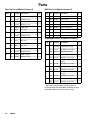
Seat Parts List (Matrix Column 4)
Ball Parts List (Matrix Column 5)
Ref.
Digit No.
Part No.
Description
Qty
Ref.
Digit No.
Part No.
Description
Qty
3
201*
189288
SEAT; 316 stainless steel
4
1
301*
112359
BALL; PTFE
4
202*
112358
O-RING; PTFE
4
2
301*
112363
BALL; acetal
4
201*
189289
SEAT; 174 stainless steel
4
4
301*
112360
BALL; 440C SS
4
202*
112358
O-RING; PTFE
4
5
301*
112745
BALL; TPE
4
201*
189292
SEAT; TPE
4
6
301*
112361
BALL; SantopreneR
4
202
None
Not Used
0
7
301*
15B492
BALL; Buna–N
4
201*
189290
SEAT; SantopreneR
4
8
301*
15B491
BALL; Fluoroelastomer
4
202*
112358
O-RING; PTFE
4
G
301*
114753
BALL; GeolastR
4
201*
15B267
SEAT; Buna–N
4
202
None
Not used
0
201*
15B265
SEAT; Fluoroelastomer
4
202
None
Not used
0
201*
189291
SEAT; polypropylene
202*
112358
201*
202*
4
5
6
7
8
9
G
Diaphragm Parts List (Matrix Column 6)
Ref.
Digit No.
Part No.
Description
Qty
401*
not sold
separately
DIAPHRAGM, backup;
polychloroprene (CR)
2
4
402*
112181
PACKING, u-cup; nitrile
2
O-RING; PTFE
4
403*
15K313
DIAPHRAGM; PTFE
2
194215
SEAT; GeolastR
4
401*
189295
DIAPHRAGM; TPE
2
112358
O-RING; PTFE
4
402*
112181
PACKING, u-cup; nitrile
2
401*
189296
DIAPHRAGM;SantopreneR
2
402*
112181
PACKING, u-cup; nitrile
2
401*
15B313
DIAPHRAGM; Buna–N
2
402*
112181
PACKING, u-cup; nitrile
2
401*
15B502
DIAPHRAGM; Fluoroelastomer
2
402*
112181
PACKING, u-cup; nitrile
2
401*
194216
DIAPHRAGM; GeolastR
2
402*
112181
PACKING, u-cup; nitrile
2
1
5
6
7
8
G
* These parts are included in the pump repair kit,
purchased separately See Repair Kit Matrix on page
23 to determine the correct kit for your pump.
28
308368
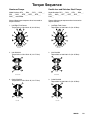
Torque Sequence
Aluminum Pumps
Ductile Iron and Stainless Steel Pumps
Model Numbers DF3___, DG3___, DFH___, DGH___,
DFC___, DGC___, DFG___, DGC___, DFG___,
DGG___ and 232503.
Model Numbers DF4___, DG4___, DF6___, DG6___,
DFD___, DGD___, DFF___, DGF___, DV4___,
DVD___
Always follow torque sequence when instructed to
torque fasteners.
Always follow torque sequence when instructed to
torque fasteners.
1. Left/Right Fluid Covers
Torque bolts to 190–220 in–lb (22–25 NSm)
1. Left/Right Fluid Covers
Torque bolts to 190–220 in–lb (22–25 NSm)
1
1
3
8
3
8
5
5
10
11
10
11
12
9
12
9
6
7
6
2
4
7
2
4
SIDE VIEW
SIDE VIEW
2. Inlet Manifold
Torque bolts to 120–150 in–lb (14–17 NSm)
16
2. Inlet Manifold
Torque bolts to 190–220 in–lb (22–25 NSm)
16
14
14
15
13
15
13
BOTTOM VIEW
BOTTOM VIEW
3. Outlet Manifold
Torque bolts to 120–150 in–lb (14–17 NSm)
3. Outlet Manifold
Torque bolts to 190–220 in–lb (22–25 NSm)
18
20
18
20
17
17
19
19
TOP VIEW
TOP VIEW
308368
29
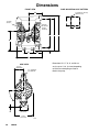
Dimensions
‘
FRONT VIEW
PUMP MOUNTING HOLE PATTERN
B
four 0.625 in. (16 mm)
diameter holes
L
1/2 npt(f)
air inlet
3/4 npt(f)
air exhaust
(muffler
included)
D
F
G
H
C
J
M
D
E
Dimensions B, C, F, G, H, and M can
SIDE VIEW
vary by up to 1/4 in. (6.3 mm) depending
6.25 in.
(158.8 mm)
2 in. (50.8 mm)
port diameter
45_
6.0 in.
(152.5 mm)
K
12.5 in.
(317.5 mm)
30
308368
7440B
on the seat and diaphragm material
fitted in the pump.
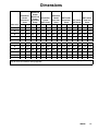
Dimensions
‘
Aluminum
Center
Aluminum
Cover
Aluminum
Center
Aluminum
Cover
Extended
Pump*
Aluminum
Center
SST Cover
Aluminum
Center
Cast Iron
Cover
SST Center
Aluminum
Cover
SST Center
SST Cover
SST Center
Cast Iron
Cover
Dimension
in.
mm
in.
mm
in.
mm
in.
mm
in.
mm
in.
mm
in.
mm
B
9.0
229
9.1
231
9.4
238
9.7
245
9.0
229
9.4
238
9.7
245
C
12.9
328
12.9
328
15.2
385
12.9
327
12.9
328
15.2
385
12.9
327
D
6.0
152
6.0
152
6.5
165
6.0
152
6.0
152
6.5
165
6.0
152
E
17.5
443
17.4
442
18.1
459
18.5
469
17.5
443
18.1
459
18.5
469
F
19.9
506
22.9
581
22.3
565
19.3
491
19.9
506
22.3
565
19.3
491
G
21.9
557
24.9
632
24.9
631
21.3
542
21.9
557
24.8
629
21.3
542
H
23.6
598
26.5
673
26.3
668
22.8
578
23.6
598
26.3
668
22.8
578
J
2.0
51
2.0
51
2.5
64
2.0
51
2.0
51
2.5
64
2.0
51
K
0.4
10
0.4
10
0.9
24
0.6
14
0.4
10
0.9
24
0.6
14
L
6.0
152
6.0
152
6.0
152
6.0
152
6.0
152
6.0
152
6.0
152
M
6.0
152
6.0
152
5.8
146
7.0
178
6.0
152
5.8
146
7.0
178
*Aluminum extended pump matches the inlet to outlet dimensions of Wilden and Aro aluminum pumps. This will
help for ease of installation during upgrades.
308368
31
Technical Data
Maximum fluid working pressure . . . . . . . . . . . . . . . . . . . . . . . . . . . . . . . . . . . . . . . . . . . . . . . . . . . . . . . . . . . . . . . . . . 120 psi
(0.8 MPa, 8 bar)
Air pressure operating range . . . . . . . . . . . . . . . . . . . . . . . . . . . . . . . . . . . . . . . . . . . . . . . . . . . . . . . . . . . . . . . . 20 to 120 psi
(0.14 to 0.8 MPa, 1.4 to 8 bar,)
Maximum air consumption . . . . . . . . . . . . . . . . . . . . . . . . . . . . . . . . . . . . . . . . . . . . . . . . . . . . . . . . . . . . . . . . . . . . 175 scfm
Air consumption at 70 psi (0.48 MPa, 4.8 bar)/60 gpm . . . . . . . . . . . . . . . . . . . . . . . . . . . . . . . . . . . 60 scfm (see chart)
Maximum free-flow delivery . . . . . . . . . . . . . . . . . . . . . . . . . . . . . . . . . . . . . . . . . . . . . . . . . . . . . . . . . . . 150 gpm (568 l/min)
Maximum pump speed . . . . . . . . . . . . . . . . . . . . . . . . . . . . . . . . . . . . . . . . . . . . . . . . . . . . . . . . . . . . . . . . . . . . . . . . . 145 cpm
Gallons (Liters) per cycle . . . . . . . . . . . . . . . . . . . . . . . . . . . . . . . . . . . . . . . . . . . . . . . . . . . . . . . . . . . . . . . . . . . . . 1.03 (3.90)
Maximum suction lift . . . . . . . . . . . . . . . . . . . . . . . . . . . . . . . . . . . . . . . . . . . . . . . . . . . . . . . . . . . . . 18 ft (5.48 m) wet or dry
Maximum size pumpable solids . . . . . . . . . . . . . . . . . . . . . . . . . . . . . . . . . . . . . . . . . . . . . . . . . . . . . . . . . . 1/4 in. (6.3 mm)
* Maximum noise level at 100 psi (0.7 MPa, 7 bar) 50 cpm . . . . . . . . . . . . . . . . . . . . . . . . . . . . . . . . . . . . . . . . . . 90 dBa
* Sound power level . . . . . . . . . . . . . . . . . . . . . . . . . . . . . . . . . . . . . . . . . . . . . . . . . . . . . . . . . . . . . . . . . . . . . . . . . . . 103 dBa
* Noise level at 70 psi (0.48 MPa, 4.8 bar) and 50 cpm . . . . . . . . . . . . . . . . . . . . . . . . . . . . . . . . . . . . . . . . . . . . . 85 dBa
Maximum operating temperature . . . . . . . . . . . . . . . . . . . . . . . . . . . . . . . . . . . . . . . . . . . . . . . . . . . . . . . . 150_ F (65.5_ C);
200_ F (93.3_ C) for models with PTFE diaphragms
Air inlet size . . . . . . . . . . . . . . . . . . . . . . . . . . . . . . . . . . . . . . . . . . . . . . . . . . . . . . . . . . . . . . . . . . . . . . . . . . . . . . . . . 1/2 npt(f)
Fluid inlet size . . . . . . . . . . . . . . . . . . . . . . . . . . . . . . . . . . . . . . . . . . . . . . . . . . . . . . . . . . . . . . . . . . . . . . . . . . . . . . . . 2” npt(f)
Fluid outlet size . . . . . . . . . . . . . . . . . . . . . . . . . . . . . . . . . . . . . . . . . . . . . . . . . . . . . . . . . . . . . . . . . . . . . . . . . . . . . . . 2” npt(f)
Wetted parts . . . . . . . . . . . . . . . . . . . . . . . . . . . . . . . . . . . . . . . . . . . . . . . . . . . . . . . . . . Vary by Model. See pages 22 to 25
Non-wetted external parts . . . . . . . . . . . . . . . . . . . . . . . . . . . aluminum, 302 and 316 stainless steel, polyester (labels)
Weight
Aluminum pumps . . . . . . . . . . . . . . . . . . . . . . . . . . . . . . . . . . . . . . . . . . . . . . . . . . . . . . . . . . . . . . . . . . . . . . 58 lb (26.3 kg)
Stainless steel pumps with aluminum center section . . . . . . . . . . . . . . . . . . . . . . . . . . . . . . . . . . . . . . . 111 lb (50.3 kg)
Ductile Iron pumps with stainless steel center section . . . . . . . . . . . . . . . . . . . . . . . . . . . . . . . . . . . . 130 lb (59.0 kg)
Stainless Steel pumps with stainless steel center section . . . . . . . . . . . . . . . . . . . . . . . . . . . . . . . . . 134 lb (61.0 kg)
Geolastr and Santoprener are registered trademarks of the Monsanto Co.
Loctiter is a registered trademark of the Loctite Corporation.
*
32
Noise levels measured with the pump mounted on the floor, using Rubber Foot Kit 236452. Sound power
measured per ISO Standard 9216.
308368
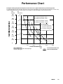
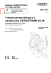
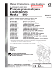
Performance Chart
Example of Finding Pump Air Consumption and Air Pressure at a Specific Fluid Delivery and Discharge Head:
To supply 60 gpm (227 liters) fluid flow (horizontal scale) at 40 psi (0.28 MPa, 2.8 bar) discharge head pressure (vertical scale)
requires approximately 50 scfm (1.68 m3/min) air consumption at 70 psi (0.49 MPa, 4.9 bar) inlet air pressure.
feet
(meters)
280
(85.3)
240
(73.2)
200
(61.0)
psi
(MPa, bar)
120
(0.8, 8)
A
80
(24.4)
40
(12.2)
0
A 120 psi air (0.8 MPa, 8 bar)
E
100
(0.7, 7)
B 100 psi air (0.7 MPa, 7 bar)
B
C 70 psi air (0.48 MPa, 4.8 bar)
F
D 40 psi air (0.28 MPa, 2.8 bar)
Air Consumption
80
(0.56, 5.6)
E 25 scfm (0.70 m3/min)
G
160
(48.8)
120
(36.6)
Inlet Air Pressures
F 50 scfm (1.40 m3/min)
C
G 75 scfm (2.10 m3/min)
60
(0.42, 4.2)
H 100 scfm (2.80 m3/min)
H
40
(0.28, 2.8)
D
20
(0.14, 1.4)
0
0
30
60
90
120
150
(114)
(227)
(341)
(454)
(568)
FLUID FLOW GPM (lpm)
TEST CONDITIONS
Pump tested in water with PTFE diaphragm
and inlet submerged.
KEY
FLUID PRESSURE AND FLOW
SCFM AIR CONSUMPTION
308368
33
Graco Warranties
Graco Standard Husky Pump Warranty
Graco warrants all equipment manufactured by Graco and bearing its name to be free from defects in material and workmanship on the
date of sale to the original purchaser for use. With the exception of any special, extended, or limited warranty published by Graco,
Graco will, for a period of five years from the date of sale, repair or replace any part of the equipment determined by Graco to be defective. This warranty applies only when the equipment is installed, operated and maintained in accordance with Graco’s written recommendations.
This warranty does not cover, and Graco shall not be liable for general wear and tear, or any malfunction, damage or wear caused by
faulty installation, misapplication, abrasion, corrosion, inadequate or improper maintenance, negligence, accident, tampering, or substitution of non-Graco component parts. Nor shall Graco be liable for malfunction, damage or wear caused by the incompatibility of
Graco equipment with structures, accessories, equipment or materials not supplied by Graco, or the improper design, manufacture,
installation, operation or maintenance of structures, accessories, equipment or materials not supplied by Graco.
This warranty is conditioned upon the prepaid return of the equipment claimed to be defective to an authorized Graco distributor for
verification of the claimed defect. If the claimed defect is verified, Graco will repair or replace free of charge any defective parts. The
equipment will be returned to the original purchaser transportation prepaid. If inspection of the equipment does not disclose any defect
in material or workmanship, repairs will be made at a reasonable charge, which charges may include the costs of parts, labor, and
transportation.
THIS WARRANTY IS EXCLUSIVE, AND IS IN LIEU OF ANY OTHER WARRANTIES, EXPRESS OR IMPLIED, INCLUDING BUT
NOT LIMITED TO WARRANTY OF MERCHANTABILITY OR WARRANTY OF FITNESS FOR A PARTICULAR PURPOSE.
Graco’s sole obligation and buyer’s sole remedy for any breach of warranty shall be as set forth above. The buyer agrees that no other
remedy (including, but not limited to, incidental or consequential damages for lost profits, lost sales, injury to person or property, or any
other incidental or consequential loss) shall be available. Any action for breach of warranty must be brought within six years of the date
of sale.
Graco makes no warranty, and disclaims all implied warranties of merchantability and fitness for a particular purpose in connection
with accessories, equipment, materials or components sold but not manufactured by Graco. These items sold, but not manufactured
by Graco (such as electric motors, switches, hose, etc.), are subject to the warranty, if any, of their manufacturer. Graco will provide
purchaser with reasonable assistance in making any claim for breach of these warranties.
In no event will Graco be liable for indirect, incidental, special or consequential damages resulting from Graco supplying equipment
hereunder, or the furnishing, performance, or use of any products or other goods sold hereto, whether due to a breach of contract,
breach of warranty, the negligence of Graco, or otherwise.
FOR GRACO CANADA CUSTOMERS
The parties acknowledge that they have required that the present document, as well as all documents, notices and legal proceedings
entered into, given or instituted pursuant hereto or relating directly or indirectly hereto, be drawn up in English. Les parties reconnaissent avoir convenu que la rédaction du présente document sera en Anglais, ainsi que tous documents, avis et procédures judiciaires
exécutés, donnés ou intentés à la suite de ou en rapport, directement ou indirectement, avec les procedures concernées.
Extended Product Warranty
Graco warrants all Husky 205, 307, 515, 716, 1040, 1590, 2150, and 3275 air valve center sections to be free from defects in material
and workmanship for a period of fifteen years from date installed in service by the original purchaser. Normal wear of items such as
packings or seals are not considered to be defects in material and workmanship.
Five years
Six to Fifteen years
Graco will provide parts and labor.
Graco will replace defective parts only.
Graco Information
For the latest information about Graco products, visit www.graco.com.–
TO PLACE AN ORDER, contact your Graco distributor or call to identify the distributor closest to you:
Phone: 612–623–6921 or Toll Free: 1–800–328–0211 Fax: 612–378–3505
All written and visual data contained in this document reflect the latest product information available at the time of publication.
Graco reserves the right to make changes at any time without notice.
Original instructions. This manual contains English. MM 308368
Graco Headquarters: Minneapolis
International Offices: Belgium, China, Japan, Korea
GRACO INC. P.O. Box 1441 MINNEAPOLIS, MN 55440–1441
Copyright 1994. All Graco manufacturing locations are registered to ISO 8001
www.graco.com
Revision ZAD, December 2013
34
308368