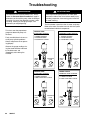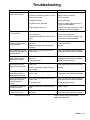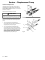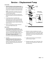
1
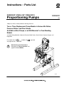
Instructions – Parts List
PRESIDENT HYDRA-CATr FIXED RATIO
Proportioning Pumps
308224H
EN
3000 psi (21 MPa, 210 bar) Maximum Working Pressure
Two or Three Displacement Pump Models in Various Mix Ratios,
Pressure Ratios, and Flow Volume
Available as Bare Pumps, or as Wall-Mounted* or Free-Standing
Models
*Includes Mixing Manifolds, Automatic Pressure Relief Valves, Check Valves, Pressure Gauges, and
Regulators.
For models that are
see pages 6 and 7.
certified and
approved
Read warnings and instructions.
See page 2 for Table of Contents and
page 6 for List of Models.
02884A
Table of Contents
Symbols . . . . . . . . . . . . . . . . . . . . . . . . . . . . . . . . . . . . . . 3
Warnings . . . . . . . . . . . . . . . . . . . . . . . . . . . . . . . . . . . . . . 3
List of Models . . . . . . . . . . . . . . . . . . . . . . . . . . . . . . . . . . 6
Typical Installation . . . . . . . . . . . . . . . . . . . . . . . . . . . . . . 8
Installation . . . . . . . . . . . . . . . . . . . . . . . . . . . . . . . . . . . . 10
Installation – Optional Fluid Heaters . . . . . . . . . . . . . . 13
Installation – Optional Solvent Pump . . . . . . . . . . . . . 15
Flushing . . . . . . . . . . . . . . . . . . . . . . . . . . . . . . . . . . . . . . 16
Operation . . . . . . . . . . . . . . . . . . . . . . . . . . . . . . . . . . . . 18
Shutdown and Care of the System . . . . . . . . . . . . . . . 21
Troubleshooting . . . . . . . . . . . . . . . . . . . . . . . . . . . . . . . 22
Service – Displacement Pump . . . . . . . . . . . . . . . . . . 24
Parts – Bare, Two Pumps . . . . . . . . . . . . . . . . . . . . . .
Parts – Bare, Three Pumps . . . . . . . . . . . . . . . . . . . . .
Parts – Wall Mount, Two Pumps . . . . . . . . . . . . . . . . .
Parts – Wall Mount, Three Pumps . . . . . . . . . . . . . . .
Parts – Stand Mount, Two Pumps . . . . . . . . . . . . . . .
Parts – Stand Mount, Three Pumps . . . . . . . . . . . . . .
Accessories . . . . . . . . . . . . . . . . . . . . . . . . . . . . . . . . . .
Dimensions . . . . . . . . . . . . . . . . . . . . . . . . . . . . . . . . . . .
Mounting Hole Layout for Air Motor . . . . . . . . . . . . . .
Technical Data . . . . . . . . . . . . . . . . . . . . . . . . . . . . . . . .
Graco Standard Warranty . . . . . . . . . . . . . . . . . . . . . .
Graco Information . . . . . . . . . . . . . . . . . . . . . . . . . . . . .
26
28
30
32
34
36
38
42
42
43
44
44
WARNING
Plural Component Materials Hazard
Graco, Inc. does not manufacture or supply any of the reactive chemical materials that may be used in this equipment and is not responsible for their effects. Because of the vast number of chemicals that could be used and
their varying chemical reactions, before using this equipment, the buyer and the user should determine all facts
relating to the materials used, including any of the potential hazards involved. Particular inquiry and investigation
should be made into the potential dangers relating to toxic fumes, fires, explosions, reaction times, and exposure
of human beings to the individual components or their resultant mixtures. Graco assumes no responsibility for
loss, damage, expense, or claims for bodily injury or property damage, direct or consequential, arising from the
use of such chemical components.
2
308224
Symbols
Warning Symbol
Caution Symbol
WARNING
CAUTION
This symbol alerts you to the possibility of serious
injury or death if you do not follow the instructions.
This symbol alerts you to the possibility of damage to
or destruction of equipment if you do not follow the
instructions.
WARNING
EQUIPMENT MISUSE HAZARD
Equipment misuse can cause the equipment to rupture or malfunction and result in serious injury.
D This equipment is for professional use only.
D Read all instruction manuals, tags, and labels before operating the equipment.
D Use the equipment only for its intended purpose. If you are not sure, call your Graco distributor.
D Do not alter or modify this equipment. Use genuine Graco parts and accessories.
D Check equipment daily. Repair or replace worn or damaged parts immediately.
D Do not exceed the maximum working pressure stated on the equipment or in the Technical Data
for your equipment. Do not exceed the maximum working pressure of the lowest rated component
in your system.
D Use fluids and solvents which are compatible with the equipment wetted parts. Refer to the Technical Data section of all equipment manuals. Read the fluid and solvent manufacturer’s warnings.
D Handle hoses carefully. Do not pull on hoses to move equipment.
D Route hoses away from traffic areas, sharp edges, moving parts, and hot surfaces. Do not expose
Graco hoses to temperatures above 66_C (150_F) or below –40_C (–40_F).
D Wear hearing protection when operating this equipment.
D Do not move or lift pressurized equipment.
D Comply with all applicable local, state, and national fire, electrical, and safety regulations.
308224
3
WARNING
INJECTION HAZARD
Spray from the valve, leaks or ruptured components can inject fluid into your body and cause extremely serious injury, including the need for amputation. Fluid splashed in the eyes or on the skin can
also cause serious injury.
D Fluid injected into the skin is a serious injury. The injury may look like just a cut, but it is a serious
injury. Get immediate medical attention.
D Do not point the valve at anyone or at any part of the body.
D Do not put your hand or fingers over the valve tip.
D Do not stop or deflect leaks with your hand, body, glove or rag.
D Do not “blow back” fluid; this is not an air spray system.
D Always have the tip guard and the trigger guard on the valve when spraying.
D Be sure the valve trigger safety operates before dispensing.
D Lock the valve trigger safety when you stop dispensing.
D Follow the Pressure Relief Procedure on page 21 if the spray tip clogs and before cleaning,
checking or servicing the equipment.
D Tighten all fluid connections before operating the equipment.
D Check the hoses, tubes, and couplings daily. Replace worn, damaged, or loose parts immediately.
Permanently coupled hoses cannot be repaired; replace the entire hose.
MOVING PARTS HAZARD
Moving parts, such as the air motor piston, can pinch or amputate your fingers.
D Keep clear of all moving parts when starting or operating the pump.
D Keep hands and fingers away from the piston during operation and whenever the pump is charged
with air.
D Before checking or servicing the equipment, follow the Pressure Relief Procedure on page 21 to
prevent the equipment from starting unexpectedly.
4
308224
WARNING
FIRE AND EXPLOSION HAZARD
Improper grounding, poor ventilation, open flames or sparks can cause a hazardous condition and result in a fire or explosion and serious injury.
D Ground the equipment and the object being sprayed. Refer to Ground the Pumps on page 10.
D If there is any static sparking or you feel an electric shock while using this equipment, stop spraying immediately. Do not use the equipment until you identify and correct the problem.
D Provide fresh air ventilation to avoid the buildup of flammable fumes from solvents or the fluid
being sprayed.
D Keep the spray area free of debris, including solvent, rags, and gasoline.
D Before operating this equipment, electrically disconnect all equipment in the spray area.
D Before operating this equipment, extinguish all open flames or pilot lights in the spray area.
D Do not smoke in the spray area.
D Do not turn on or off any light switch in the spray area while spraying or while operating if fumes
are present.
D Do not operate a gasoline engine in the spray area.
TOXIC FLUID HAZARD
Hazardous fluid or toxic fumes can cause serious injury or death if splashed in the eyes or on the skin,
inhaled, or swallowed.
D Know the specific hazards of the fluid you are using.
D Store hazardous fluid in an approved container. Dispose of hazardous fluid according to all local,
state and national guidelines.
D Always wear protective eyewear, gloves, clothing and respirator as recommended by the fluid and
solvent manufacturer.
308224
5
List of Models
Pressure and Ratio Ratings for President Pumps
WARNING
To reduce the risk of over pressurizing a component, which can result in an explosion and serious injury, never
operate the system at a working pressure higher than the lowest rated component in the system. All fluid side
components such as dispensing valves, regulators, and hoses must have a working pressure equal to or greater
than the pressure given in Column B for each pump model.
Column A gives the maximum fluid pressure developed at 100 psi (0.7 MPa, 7 bar) of incoming air pressure.
Column B gives the minimum working pressure required for all system components, based on the automatic
relief valve settings. Components included by Graco with the models listed meet or exceed this requirement.
Models with Two Displacement Pumps
Model No.
B
Minimum
Component
Working Pressure
Normal
Pressure
Ratio
(Fluid to Air)
Nominal Flow
Volume
@ 40 cpm
Mix Ratio
Bare
Wall
Stand
psi
bar
psi
bar
1:1
231643**
231593**
231618**
1280
89
1800
124
12.80
1.5
5.7
1:1
231644
1601
112
1800
124
16.01
1.2
4.5
1:1
231645**
1921
135
2300
159
19.21
1.0
3.8
1:1
231646**
2561
179
2900
200
25.61
0.75
2.8
** CE approved and
6
A
Maximum Pump
Fluid Pressure
at 100 psi (7 bar) Air
308224
231595**
certified.
gpm
lpm
List of Models
Models with Three Displacement Pumps
Model No.
Mix Ratio
A
B
Maximum Pump
Fluid Pressure
at 100 psi (7 bar) Air
Minimum
Component
Working Pressure
Bare
Wall
Stand
psi
bar
psi
bar
2:1
231657**
231607**
231632**
1280
88
1800
124
2:1
231658**
1707
118
1800
4:1
231663**
1024
71
1150
**CE approved and
231613**
231638**
Normal
Pressure
Ratio
(Fluid to Air)
Nominal Flow
Volume
@ 40 cpm
gpm
lpm
12.80
1.50
88
124
17.07
1.12
118
79
10.24
1.87
71
certified
308224
7
Typical Installation
NOTE: When pressure feeding the proportioning
pump, mount fluid pressure gauges (J) at the proportioning pump inlets to monitor proper adjustment of the
feed pump pressures. Never exceed 25% of the
Hydra-Cat pump outbound fluid pressure on the feed
supply.
About the Typical Installations
These pumps are designed to be part of a Hydra-Cat
dispensing system that will proportion, mix, and
dispense two-component fluids. The typical installations shown below and on page 9 are only guidelines
to setting up a complete proportioning system. For
clarity, various components are shown in the correct
order but may not be shown in exactly the position of
the installed system. For assistance in designing your
system, contact your Graco distributor.
Light Viscosity System
Two Displacement Pumps,
5:1 Ratio Feed Pumps
KEY
A
B
C
D
E
F
G
Bleed-type master
air valve
Air filter
Air lubricator
Pump runaway valve
Pump air regulator
Feed pump
Ground wire
B
H
J
K
L
Proportioning pump
Fluid pressure gauge
Check valve
Automatic pressure relief
valve
M Fluid filter
N Mixer manifold
P
Q
R
S
T
U
V
Fluid drain valve
Fluid shutoff valve
Static mixer
Dispense valve
Fluid regulator
Solvent pump
Fluid strainer
1
See note above
2
Connect to drain bottle.
See Fig. 5, page 11
*
Included with wall or stand models
A
F
H
G
J* K*
L*
M
S
N*
C
P*
R
D
HARD
E*
E
RES
A*
A
2
HARD
RESIN
Q
T
U
M
RES
HARDENER
Q*
K
J*
1
V*
Q*
02885
Fig. 1
8
308224
Typical Installation
NOTE: When pressure feeding the proportioning
pump, mount fluid pressure gauges (J) at the proportioning pump inlets to monitor proper adjustment of the
feed pump pressures. Never exceed 25% of the
Hydra-Cat pump outbound fluid pressure on the feed
supply.
About the Typical Installations
These pumps are designed to be part of a Hydra-Cat
dispensing system that will proportion, mix, and
dispense two-component fluids. The typical installations shown below and on page 8 are only guidelines
to setting up a complete proportioning system. For
clarity, various components are shown in the correct
order but may not be shown in exactly the position of
the installed system. For assistance in designing your
system, contact your Graco distributor.
Heavy Viscosity Heated System
Three Displacement Pumps,
10:1 Ratio Feed Pumps
KEY
A
B
C
D
E
F
G
H
Bleed-type master air valve
Air filter
Air lubricator
Pump runaway valve
Pump air regulator
Feed pump
Ground wire
Proportioning pump
B
J
K
L
Fluid pressure gauge
Check valve
Automatic pressure
relief valve
M Fluid filter
N Mixer manifold
P Fluid drain valve
Q Fluid shutoff valve
R
S
T
U
V
W
X
Static mixer
Dispense valve
Fluid regulator
Solvent pump
Fluid strainer
Fluid heater
Supply manifold
1
See note above
2
Connect to drain bottle.
See Fig. 5, page 11
*
Included with wall or stand models
A
F G
H
J*
K* L*
W
M
S
N*
C
P*
R
D
2
E
E*
Q
A*
Q*
K
A
2
X
J*
T
U
M
1
V*
Q*
02886
Fig. 2
308224
9
Installation
Bare Pumps
Bare pumps are available for those installations which
require a highly customized system. For a safe and
efficient system, Graco recommends that the air and
fluid components supplied with the Wall Mount and
Cart Mount models also be used in customized
systems. Refer to the Parts Drawings on pages 26–37
for part numbers. In addition, the accessories shown in
the Typical Installation drawings and discussed in the
following pages of this manual should be used.
For a wall mount, be sure the bracket and wall are
strong enough to support the pump, accessories,
plumbing and stress caused by pump operation.
Locate the bracket about 5 ft (1.5 m) above the floor.
Ground the Pumps
WARNING
FIRE AND EXPLOSION HAZARD
Before operating the pump, ground the
system as explained below. Also read
the section FIRE AND EXPLOSION
HAZARD on page 5.
Be sure all accessories are sized properly for the air
and fluid requirements of your system.
Read all instructions in the Installation section for
further details.
NOTES:
1. Models with three displacement pumps always use
the two outer displacement pumps to supply the
resin and the middle displacement pump to supply
the hardener.
1. These pumps always use the two outer displacement pumps to supply the resin and the middle
displacement pump to supply the hardener.
1. Loosen the grounding lug locknut (BB) and washer
(AA).
2. Insert one end of a 14 ga (1.5 mm@) minimum
ground wire (G) into the slot in lug (CC) and tighten the locknut securely. See Fig. 3.
3. Connect the other end of the ground wire to a true
earth ground. Order part number 237569 Grounding Clamp and wire.
2. Label all pumps, hoses, fluid regulators, etc. to
indicate whether they are for the resin side or
hardener side of the system.
G
Mounting the Pump
Mount the pump to suit your installation. The bare
pump can be mounted on a wall bracket or on a cart.
See the Mounting Hole Layout on page 42. The President pump and accessories weigh approximately 65 lb
(30 kg). The pump stand and accessories weigh
approximately 55 lb (25 kg).
10
308224
AA
Fig. 3
BB CC
Installation
Air Control Accessories
Automatic Pressure Relief Valves
Install the accessories in the order shown in Fig. 4.
Mount only the air regulator (E) and a master air valve
(A) at the pump. Mount all other accessories on separate wall brackets to reduce stress on the pump inlet.
Note that one air filter (B) can serve multiple pumps by
using an air manifold downstream from the air filter.
WARNING
Bleed-type master air valves (A) are required in the
system in the positions shown in the Typical Installation drawings. These valves are used during
system pressure relief to relieve air trapped in the
air line. Trapped air can cause the pump to cycle
unexpectedly and result in serious injury from
moving parts, fluid injection, or fluid splashing.
1. Install a bleed-type master air valve (A) in the
pump air inlet.
2. Install an air regulator and gauge (E) to control
pump outlet pressure.
3. Install a pump runaway valve (D) for each feed
pump to automatically shut off the air to the pump
if the pump accelerates beyond the pre-adjusted
setting. A pump which runs too fast can be seriously damaged.
WARNING
To reduce the risk of component rupture, which
could cause serious injury and property damage,
the appropriate automatic pressure relief valve is
required for each fluid on a plural component
pump.
These valves automatically relieve fluid pressure if
the pump output pressure exceeds the valve’s
preset pressure. Over pressurization may occur if
there is a fluid line clog upstream from the valve or
if any other condition exists that causes one of the
pumps to cavitate and direct all fluid pressure to
the other pump(s).
See the List of Models on page 6 to determine
the preset pressure in your system.
Two drainage bottle kits (38) are included with wall
models (unassembled) and stand mount models
(assembled) to catch the drainage if the automatic
pressure relief valves open.
For the wall mount models, assemble the kit as shown
in Fig. 5 and mount it securely to a wall or bracket.
Use the tie wrap, supplied, to hold the hoses out of the
way, if necessary.
WARNING
4. Install an air line lubricator (C) for automatic air
motor lubrication.
5. Install an air filter (B) to remove harmful dirt and
moisture from the compressed air supply.
B
A
Fluid emitted from the automatic pressure drain
valves may be at pressures over 3000 psi (21
MPa, 210 bar). Make sure the drain bottles are
securely fastened to the frame or wall so that they
can handle a sudden spurt of pressurized fluid.
18
A
E
38a
38b
G
38c
C
Fig. 4
38f
38g
38h
D
02887
02888A
Fig. 5
308224
11
Installation
DD
NOTE: If you mount the pump on a wall, turn the
displacement pump inlet assemblies (CC) to face
forward, rather than backwards as shown in Fig. 6.
EE
37B
Connect Fluid Supply Hoses
RES
For Two Displacement Pump Models
HARD
1. Connect the resin supply hose (EE) to the 3/4 npt
swivel inlet (37B) for the resin displacement pump.
See Fig. 6.
37A
2. Connect the hardener supply hose (DD) to the
3/4 npt swivel inlet (37A) for the hardener displacement pump. See Fig. 6.
CC
02889
Fig. 6
For Three Displacement Pump Models
37B
RES
2. Connect the hardener supply hose (DD) to the 3/4
npt swivel inlet (37) for the center (hardener)
displacement pump. See Fig. 7.
HARD
RES
1. Connect the resin supply hose (EE) to the 3/4 npt
swivel inlet (37B) for the resin displacement
pumps. See Fig. 7.
EE
Additional System Components
Install and connect the feed pumps, solvent pump,
heaters, etc. Refer to the Typical Installation (Fig. 1–2)
and Accessories on pages 38–39 for parts information.
Use a dry air kit or a nitrogen regulator kit to protect
the fluid in the supply containers from moisture that
can crystallize the fluid and cause the ball checks to
malfunction. See Accessories on page 39.
12
308224
DD
37A
Fig. 7
02890
Installation – Optional Fluid Heaters
All Models
NOTE: For systems requiring one heater for each
fluid, see page 38 to order the heaters and required
plumbing (items 201 to 205).
201a
201b
201
202
204
OUT
1. Mount a heater to each side of the mounting
bracket using the three screws (201a) and lockwashers (201b) supplied with each heater. See
Fig. 8.
2. Connect a swivel union (202) to the outlet of each
heater. See Fig. 8.
IN
3. Connect a swivel union (203) to the inlet of each
heater. See Fig. 8.
For Two Displacement Pump Models
203
1. Disconnect the existing hardener hose (10B) from
the inlet of the mixer manifold (23). See Fig. 8.
Connect the free end of the hose to the swivel
(203) at the hardener heater inlet. See Fig. 9.
10
02891A
Fig. 8
2. Install a new fluid hose (204B) between the
hardener heater outlet (202B) and the hardener
mixer manifold. See Fig. 8–9.
WARNING
To reduce the risk of serious injury, follow the
Pressure Relief Procedure on page 21 before
installing the heaters.
3. Repeat Steps 1 and 2 for the resin pump
(the “A” side).
23 (N)
HARD
RES
204B
204A
202B
202A
RE
S
HAR
D
OUT
OUT
RES
203A
HARD
RES
10A
IN
HARD
IN
203B
10B
02893
Fig. 9
308224
13
Installation – Optional Fluid Heaters
23 (N)
204B
205A
FA
RES
RES
HARD
17A
202A
FB
HARD
17B
RES
HEATE
R
OUT
RES
HARD
RES
IN
202B
HARD
HEATE
R OUT
IN
203A
203B
02894
Fig. 10
For Three Displacement Pump Models
16A
17A
NOTE: You must provide two hoses (FA, FB in Fig.10)
and fittings to run from the heater outlets to the mixer
manifold inlets.
17B
16B
NOTE: To accommodate two resin fluid hoses, the
mixer manifold (23) must be disconnected from the
bracket and mounted remotely.
3. Install another hardener fluid hose (FB) between
the heater outlet elbow (202B) and the hardener
side of the mixer manifold (23). See Fig. 10.
4. Repeat Steps 1 to 3 for the resin side of the
system (the “A” side).
14
308224
HARD
2. Connect a new hardener fluid hose (204B)
between the union (17B) and the swivel (203B) at
the heater inlet. See Fig. 10.
RES
1. Loosen the swivel of the unions (17A, 17B) to
remove the elbow (16A, 16B) on each side of the
mixer manifold (23). Turn the unions (17A, 17B) so
the outlet faces up. See Fig. 10 and 11.
(N) 23
02892A
Fig. 11
Installation – Optional Solvent Pump
NOTE: The optional solvent pump is not offered as a
kit; order parts as needed. The optional parts shown
here are listed on page 39. These instructions assume
that the pump is being mounted to the back of the
stand offered in this manual. The Typical Installations
on pages 8–9 show alternate installations. Adjust
your installation according to your specific needs.
4. Couple the hose (303) and couplings (302).
Connect the hose (303) to the adapter (301).
5. Install the other adapter (301), needle valve (304)
and adapter (305) to the pump inlet.
6. Connect the adapter (307), elbow (308) and fluid
hose (309) to the pump outlet.
1. Mount the solvent pump bracket (301) on the back
of the stand.
2. Mount the pump (306) to the bracket using the
hardware supplied with the pump.
7. Install a fluid shutoff valve (311) at the mixer
manifold swivel union (15). This valve is used to
prevent resin or hardener from backing up into the
solvent system, and to isolate the solvent system
for service. Connect the solvent inlet hose (309).
3. Use the existing proportioning pump air regulator
(5) to supply air to the solvent pump. Remove the
plug from the back of the swivel union (3) and
install the adapter (301). Rotate the regulator
gauge elbow (4) so the gauge is facing the
operator.
8. Connect the suction hose assembly (312) to the
pump intake.
309
305
A
306
A
311
15
303
302
301
304
307
308
B
3
309
4
316
315
310
301
302,
303
314
313
B
5
312
02902B
Fig. 12
308224
15
Flushing
When to Flush the System
How to Operate the Mixer Manifold
D Flush the system before its first use to remove the
light oil which was left in after factory testing.
To open or close the mixer manifold (N) fluid valves
(LL) push the handle (KK) down to open and up to
close. See Fig. 13.
D Flush the manifold mixer (N), using the solvent
pump, as frequently during the day as necessary to
avoid exceeding the pot life limit of the material
being pumped.
KK
1
UP – closed
2
DOWN – open
LL
LL
1
D Flush frequently enough during regular operation to
prevent clogged passages due to material being
overheated or dried out in any part of the system.
Clogged passages in the heater can be very difficult
to clean and can reduce heating efficiency, flow rate
and pressure.
2
N2
RES
HARD
N1
N
D Flush the entire system when the system is shut
down for a long period of time. Keep in mind that
some moisture may get into the lines, which could
contaminate the hardener, so flush again before
restarting the system.
P1
P2
02895
Fig. 13
KEY
A
Bleed-type master air valve
E
A1
A2
A3
A4
A5
Hardener feed pump
Resin feed pump
Proportioning pump
Solvent pump
Feed & Proportioning pump
master air valve
A6 Solvent pump master air valve
Pump air regulator
E1
E2
E3
E4
J
H
N
Q
Hardener feed pump
Resin feed pump
Proportioning pump
Solvent pump
Proportioning pump
Mixer manifold
Fluid shutoff valve
Q1 Proportioning pump intake
Q2 Mixer manifold solvent inlet
Fluid pressure gauge
J1 Proportioning pump intake
J2 Proportioning pump outlet
A6
A5
E3
A3
Q2
H
N
HARD
HARD
A2
A1
E1
E2
RES
RES
Fig. 14
16
308224
J2
J1
E4
Q1
A4
02896
Flushing
How to Flush the System
WARNING
If your system is equipped with heaters, always
shut off the main power to the heaters before
flushing. Circulate the fluid through the system for
at least 10 minutes to cool the fluid and the heater.
This reduces the risk of serious injury from burns.
NOTE: For the first time flushing, we recommend
using mineral spirits solvent (also called white spirit) to
flush out the oil. Then flush again using a solvent that
is compatible with the fluid you will be dispensing.
However, be sure the mineral spirits solvent is compatible with the material you will be pumping. If it is not,
check with your fluid supplier to determine an
appropriate solvent for flushing out the light oil.
To flush the solvent valves . . .
11. Open the hardener solvent flush valve (N1) on the
mixer manifold (N). See Fig. 13.
a. Be sure the solvent pump air regulator (E4) is
at minimum pressure. See Fig. 14.
b. Open the solvent pump main master air valve
(A6) and then open the pump air valve (A4).
See Fig. 14.
c.
Release the dispensing valve safety latch.
Hold the dispensing valve firmly against a
grounded pail and trigger it while slowly
opening the solvent pump air regulator (E4).
Operate the pump slowly until the dispense
line is flushed. Release the dispensing valve
trigger and engage its safety latch. Close the
hardener solvent flush valve (N1).
For flushing only . . .
d. Open the resin solvent flush valve (N2) and
repeat Step c. See Fig. 13.
NOTE: The proportioning pump is not operated during
flushing. The solvent from the feed pumps will flush the
proportioning pump displacement pumps.
e. Close the solvent line shutoff valve (Q2). See
Fig. 14.
1. Place each feed pump intake into a separate 5
gallon grounded pail, containing about 3 gallons
(12 liters) of solvent.
To flush or prime . . .
2. Be sure both of the fluid shutoff valves (Q1) are
open. See Fig. 14.
3. Place a container under the drain valves (P1,P2)
of the mixer manifold (N). See Fig. 13.
4. Be sure the feed pump air regulators (E1,E2) are
at minimum pressure. See Fig. 14.
5. Open the main master air valve (A5). See Fig. 14.
6. Open the hardener pump master air valve (A1).
See Fig. 14.
CAUTION
Always close the solvent line fluid shutoff valve (Q2)
after the flushing procedure has been completed.
This will prevent the other fluids from leaking into the
flushing line.
If this is a first time flush . . .
12. Repeat the flushing procedure using a solvent
compatible with the fluid you are going to
dispense.
When you are done flushing . . .
13. Remove the solvent supply from the feed pumps.
Operate the pumps slowly to push all the solvent
out of the lines, then stop the pumps.
If you are not going to use the system . . .
7. Slowly increase the air regulator (E1) setting until
the pump is running slowly.
8. Open the hardener side drain valve (P1). Open the
mixer manifold handle (KK). See Fig. 13.
9. When the hardener lines are flushed, close the
mixer manifold handle and close the drain valve
(P1). Close the air valve (A1). See Fig. 14.
10. Repeat Steps 6 to 9 for the resin feed pump. The
resin sides uses these parts: regulator (E2), air
valve (A2), drain valve (P2).
14. Close all air regulators, master air valves and fluid
shutoff valves. Follow the Pressure Relief Procedure on page 21.
WARNING
Always close the air valve (A4) to the solvent pump
before opening the fluid drain valves (P2) to relieve
system pressure. This will reduce the risk of excessive pressure buildup in the opposite component
hose and fittings.
308224 17
Operation
Check the Drainage Bottles and Hoses
WARNING
WARNING
Handling Plural Component Materials
Be extremely cautious when handling plural component materials and solvents used with them.
Some are extremely toxic. See the WARNING on
the front cover. Read and follow the coating and
solvent manufacturer’s safety precautions and
warnings, including information regarding protective
clothing, eyewear, and respirators.
When spraying reactive fluids, wear the proper
protective clothing, eye protection, gloves, and
clean air breathing apparatus as prescribed by the
fluid manufacturers recommendations, O.S.H.A.
regulations and as approved by N.O.I.S.H. for the
chemicals being used.
Observe the Pot Life Limit
To reduce the risk of serious injury and property
damage, regularly check and clean the drain hose
and bottle for the automatic pressure relief valve.
If material is allowed to dry in and clog the drain
hose, the automatic pressure relief valve may not
fully release the fluid pressure if it opens or may
cause the drain hose to burst.
Check the drain hose and bottle (38) at the start of
each shift, and whenever there is an imbalance of
material, to see if the automatic pressure drain valve
has released material into the bottles. Clean the hose
and bottle as needed. Regularly check the drain hose
for cuts, leaks, or bulges and replace damaged
components before using the system. See Fig. 16.
Flush the mixed fluid out of the mixer, dispensing lines
and equipment before it hardens. Flush the complete
system when necessary to prevent the fluids from
hardening in the equipment and hoses. Check the fluid
manufacturer’s instructions for fluid shelf life, and flush
the entire system before this time is reached. Flush the
system with a compatible solvent as explained on page
17.
Fill the Throat Packing Nuts
Verify compatibility of the pump oil with the fluids being
used in the pumps. During operation very small
amounts of this fluid are dragged past the seals and
into the pump.
308224
Monitor the Material Supply
CAUTION
Establish a rigid system for monitoring the material
supply to prevent the pumps from running dry. A
sudden lack of material in one pump may cause
many system problems, including air entrapment,
spitting of the fluids, fluid “crossovers”, pump
damage, downtime, and added system stresses.
Never allow the feed pump or solvent pump containers
to run dry. A dry container allows air to be pumped into
the system and causes incorrect proportioning. A dry
pump will quickly accelerate to a high speed, and may
damage itself and the other displacement pump because it causes a pressure rise in the other pump. If a
supply container becomes dry, stop the pump immediately, refill the container, and prime the system. Be
sure to eliminate all the air from the system.
JJ
18
02948A
Fig. 16
Keep each displacement pump throat packing nut (JJ)
filled with Graco ISO Pump Oil to help prevent fluid
from drying on the displacement rod and damaging the
pump packings. See Fig. 15.
Fig. 15
38
02897
NOTE: The pump runaway valve mentioned on page
11 of the Installation section shuts off the pump if the
pump speed accelerates quickly.
Operation
6. Open the mixer manifold (N) and trigger the
dispense valve (S).
Startup
WARNING
7. Set the air pressure to the feed pumps at 88 psi
(0.6 MPa, 6 bar) or 25% of proportional pressure
at the fluid outlets, whichever is less. Use the
gauges (J1) to monitor this pressure. Higher
pressures may prevent the proportioning pump
inlet ball checks from setting properly.
To reduce the risk of serious bodily injury, including
fluid injection, splashing in the eyes or the skin, and
property damage, never exceed the maximum air
and fluid working pressure of the lowest rated
component in your system. See Equipment Misuse Hazard, System Pressure, on page 3.
8. Set the air pressure to the proportioning pump (H)
to obtain the required fluid pressure. Refer to the
proportioning pump chart on page 6 for the fluid
to air pressure.
1. Install full containers of resin and hardener at the
feed pumps.
9. While triggering the dispensing valve, check the
fluid outlet pressure gauges (J2) and make note of
the pressures indicated. Check the gauges
frequently during operation. These notes will help
to analyze any problems that may occur since a
change in displacement pump performance will be
indicated by a change in pressure gauge
readings.
2. To prime the system, follow Steps 2 to 11 of the
Flushing procedure on page 17.
3. Turn on the heaters, if used, and allow them to
warm up for 10 minutes.
4. Open the feed pump air valves (A1,A2). Adjust the
air regulators (E1,E2) just enough to start the
pumps operating slowly.
NOTE: A pressure drop does occur during pump
stroke changeover.
5. Open the proportioning pump air valve (A3) and
slowly open the regulator (E3) to start the proportioning pump.
NOTE: Flush the mixer manifold frequently during the
day’s operation. Follow Step 11 on page 17.
KEY
A
Bleed-type master
air valve
E
A1 Hardener feed pump
A2 Resin feed pump
A3 Proportioning pump
Pump air regulator
E1 Hardener feed pump
E2 Resin feed pump
E3 Proportioning pump
E3
A3
H
N
S
Proportioning pump
Mixer manifold
Dispense valve
H
S
N
A2
A1
E1
Fig. 17
E2
02886
308224
19
Operation
NOTE: Since this is a fixed ratio system, you typically
do not have to check the mix ratio.
10. While observing the pump outlet gauges (J2),
adjust the resin and hardener drain valves (P1,P2)
until the gauges show your normal operating
pressure.
If the mixed fluid does not cure or harden properly,
check the ratio of resin to hardener.
NOTE: The pressure must be within 20% of the original spraying pressure to get a usable test.
Checking the Mix Ratio
1. Flush the mixer manifold; see Step 11 on page 17.
2. Follow the Pressure Relief Procedure on page .
3. Open the mixer manifold (N).
4. Set the operating pressure for the pumps. See
Steps 7 and 8 on page 19.
5. Release the dispensing valve trigger and engage
the safety latch.
6. Close the mixer manifold (N).
7. Open the hardener side drain valve (P2) about
three turns. Open the resin side drain valve (P1)
about 1 turn. This prevents the pressure from
building up on the hardener pump, which would
cause the automatic pressure relief valve to open.
11. Close the mixer manifold. Put a separate sampling
container under each drain valve.
12. Open the mixer manifold to draw a sufficient
sample.
13. As you close the mixer manifold, check the pump
outlet gauges (J2) again to make sure they are at
your normal operating pressure.
NOTE: If the fluid pressure is not within 20% of the
normal operating pressure, flush the mixer manifold
again and take another sample. If the sample ratio is
incorrect, refer to the Troubleshooting chart on page
22. If the ratio is correct, the problem is with one of the
other system components.
8. Place a grounded metal pail under the drain
valves.
14. Compare the volume of the sampling containers. If
the ratio is not correct, refer to the Troubleshooting
chart on page 22. If the ratio is correct the problem
is one of the other components.
9. Open the mixer manifold.
15. Close the drain valves (P1,P2).
J2
KK
N
P1
P2
Fig. 18
20
308224
J2
02898A
Shutdown and Care of the System
Pressure Relief Procedure
WARNING
INJECTION HAZARD
The system pressure must be manually
relieved to prevent the system from
starting or spraying accidentally. Fluid
under high pressure can be injected through the
skin and cause serious injury. To reduce the risk of
an injury from injection, splashing fluid, or moving
parts, follow the Pressure Relief Procedure
whenever you:
D
D
D
D
are instructed to relieve the pressure,
stop spraying,
check or service any of the system equipment,
or install or clean the spray tips.
1. Engage the dispensing valve safety latch.
2. Shut off the feed pump and proportioning pump air
regulators and bleed-type master air valves.
3. If the system has heaters, circulate the fluid for at
least 10 minutes to cool the heated fluid and
heater.
If you suspect that the nozzle or hose is completely
clogged, or that pressure has not been fully relieved
after following the steps above, very slowly loosen the
nozzle or hose end coupling and relieve pressure
gradually, then loosen completely. Now clear the
nozzle or hose.
System Shutdown
To shut the system down, shut off the air to all pumps,
trigger the dispensing valve into a grounded metal
waste container. Close the mixer manifold valves.
Flush all the mixed fluid out of the mixer manifold,
hoses and dispensing equipment. See page 17. Then
follow the Pressure Relief Procedure.
Cleaning the Pump Inlet Strainer
If the fluid pressure from the feed pump to the proportioning pump cannot be maintained on the proportioning pump intake gauge (J), check and clean the
strainer (V).
Care of the Pump Throat Packing Nuts
Keep the throat packing nuts filled with appropriate
lubricant and check the tightness of the packing nut
weekly. See Fig. 19. The packing nut should be tight
enough to prevent leakage; no tighter. Too tight an
adjustment causes the packings to bind or wear prematurely and leak. Always follow the Pressure Relief
Procedure before adjusting the packing nut.
4. Disengage the dispensing valve safety latch.
5. Hold a metal part of the dispensing valve firmly to
the side of a grounded metal pail, and trigger the
dispensing valve to relieve pressure.
6. Engage the safety latch.
7. Open the mixer manifold drain valves (required in
your system), having a container ready to catch
the drainage. Close the valves immediately.
8. Use the solvent pump to flush the mixer manifold
valves.
JJ
Fig. 19
308224
21
Troubleshooting
WARNING
WARNING
To reduce the risk of serious bodily injury, always
follow the Pressure Relief Procedure on page 21
whenever you shut off the pump, when checking or
servicing any part of the dispensing system, when
installing, cleaning or changing fluid tips, and
whenever you stop dispensing.
This chart uses the proportioner
gauges to determine pump malfunctions.
Faulty manifold check valves can
mask pump cylinder problems.
Always keep these valves operating properly.
Never operate the pump with the air motor plate
removed, to reduce the risk of serious bodily injury,
including amputation, from moving parts inside the
air motor housing.
The chart below is specific to the air motor and pump.
Refer to the other instruction manuals with the system
to troubleshoot individual components.
TROUBLE AREA:
RESIN PUMP LEAKAGE
TROUBLE AREA:
HARDENER PUMP LEAKAGE
1. THROAT PACKING
2. PISTON PACKING
3. PISTON BALL CHECK
1. THROAT PACKING
2. PISTON PACKING
3. PISTON BALL CHECK
Observe the gauge readings during the stroke direction indicated
by the bold arrow, and
immediately after closing the
manifold.
22
308224
RESIN
PUMP
HARDENER
PUMP
RESIN
PUMP
HARDENER
PUMP
FALLING
RISING
RISING
FALLING
TROUBLE AREA:
RESIN PUMP LEAKAGE
TROUBLE AREA:
HARDENER PUMP LEAKAGE
1. THROAT PACKING
2. FOOT VALVE BALL CHECK
1. THROAT PACKING
2. FOOT VALVE BALL CHECK
RESIN
PUMP
HARDENER
PUMP
RESIN
PUMP
HARDENER
PUMP
FALLING
RISING
RISING
FALLING
Troubleshooting
Problem
System won’t run or
stops while running.
Solution
Air pressure or volume too low.
Increase, check air compressor.
Closed or restricted air line or air valve.
Open or clean as required.
Fluid valves closed.
Open fluid valves.
Clogged fluid hose.
Replace fluid hose.
Air motor worn or damaged.
Service air motor. See instructions in
separate manual 306982.
Displacement pump stuck.
Service pump. See instructions in separate manual 307944 or 684004.
Fluid containers are empty.**
Check often – keep filled.
Air in fluid lines.**
Purge, check connections.
Displacement pump parts worn or damaged.
Service pump. See instructions in separate manual 307944 or 684004.
Pump operates but resin
output pressure drops
during upstroke.*
Dirty, worn or damaged resin pump piston valve.
Clean, service pump. See instructions
in separate manual.
Worn or damaged resin pump piston
packings.
Replace.
Pump operates but resin
output pressure drops during downstroke.
Dirty, worn or damaged resin pump n
intake valve.
Clean, service pump. See instructions
in separate manual 307944 or 684004.
Pump operates but resin
output pressure drops
during both strokes.*
Dirty, worn or damaged resin pump piston valve.
Clean, service pump. See instructions
in separate manual 307944 or 684004.
Fluid supply low.**
Refill or change container.
Pump operates but hardener output pressure
drops during upstroke.*
Dirty, worn or damaged resin pump intake valve.
Clean, service pump. See instructions
in separate manual 307944 or 684004.
Worn or damaged hardener pump piston packings.
Replace.
Pump operates but hardener output pressure
drops during downstroke.*
Dirty, worn or damaged hardener pump
intake valve.
Clean, service pump. See instructions
in separate manual 307944 or 684004.
Pump operates but hardener output pressure
drops during both
strokes.
Dirty, worn or damaged hardener pump
intake valve.
Clean, service pump. See instructions
in separate manual 307944 or 684004.
Fluid supply low.**
Refill or change container.
Fluid leaks around fluid
pump packing nut.
Loose packing nut or worn throat packings.
Tighten, replace.
Relief valve opens too
soon or won’t close.
Relief valve needs adjusting or is
damaged.
Adjust, service pump. See instructions
in separate manual 307944 or 684004.
System speeds up or
runs erratically.
*
Cause
Fluid ratio will be wrong.
**
Purge all air out of the system before
proportioning the fluids.
308224
23
Service – Displacement Pump
Removal and Replacement
33
Stop the pump at the bottom of its stroke.
HARD
RES
Thoroughly flush the system with a solvent which is
compatible to the fluid being pumped, then follow the
Pressure Relief Procedure on page 21. The Flushing
procedure is on page 17.
CAUTION
If you are changing to a different type of fluid, completely clean all of the equipment and hoses, making
sure that no fluid remains in any part of the system.
125
308224
RES
24
HARD
2. For Three Displacement Pump Models Only
Unscrew the swivel union (33) from the bottom of
the center displacement pump. Unscrew the swivel
unions (126) from the outer displacement pumps.
Remove the supply manifold (125) from the outer
pumps. Unscrew the straight union (39) from the
center displacement pump. See Fig. 21.
RES
Remove the fluid outlet hoses from the displacement
pumps.
1. For Two Displacement Pump Models Only
Unscrew the swivel unions (33) from the bottom of
the displacement pumps. See Fig. 20.
33
Fig. 20
41
39
126
Fig. 21
33
Service – Displacement Pump
Disassembly
1. Remove the locknuts (113) from the top of the
yoke (114) of the two outer displacement rods. See
Fig. 22. Unscrew the outer locknuts (122) from the
top of the tie plate (123) on the two displacement
pumps. Use a screwdriver and hammer to loosen.
NOTE: The tie rods (111) shown in Fig. 22 are
removed from the tie plate (121) for clarity only
and do not require removal.
2. Remove the two outer pumps from the tie plate.
Remove the washers (115) from the rods of each
pump.
3. Three Displacement Pump Models Only.
Using a wrench on the flats of the center pump’s
displacement rod, screw the rod out of the yoke
(114). See Detail B in Fig. 22. Remove the pump
from the yoke (114) then the washer (115) from the
rod on the pump.
4. Refer to the appropriate instruction manual for
servicing the displacement pump.
113
1
111
115
114
122
123
1
122
Torque to
53–67 ft-lb
(72–91 NSm)
121
1
DETAIL B
C
Fig. 22
Reassembly
1. Three Displacement Pump Models Only.
Slide the center displacement pump rod through
the tie plate (121), center locknut (123), and washer (115). Thread the displacement rod into the
yoke (114) by turning the complete cylinder. Use a
wrench on the flats of the displacement rod for
final tightening. Torque to 53–67 ft-lb
(72–91 NSm). Push the cylinder up into place in
the tie plate and install the center locknut (123).
2. All pumps
Slide the outer two displacement pump rods
through the tie plate (121), outer locknuts (122),
and washers (115). Install the locknuts (113)
loosely on the displacement rods. Push the cylinders up into place in the tie plate and install the
outer locknuts (122).
3. Move the air motor to the bottom of its stroke.
Check for movement of the air motor yoke at each
displacement rod. With the rods centered, tighten
the locknuts (113) securely and torque to 53–67 ftlbs (72–91 NSm).
4. Tighten the throat packing nut just enough to
prevent leakage, no tighter.
5. Reconnect the swivel unions to the pumps. Hold
the intake valve (C) steady with a wrench to prevent from turning.
308224
25
Parts – Bare, Two Pumps
Models 231643–231646
101
113
1
102
114
103
111
3
104
3
115
105
122
106
107
121
108
107
2
116
109
105
110
1
112
26
1
Torque to 53–67 ft-lb (72–91 NSm)
2
Apply anaerobic sealant and torque to 100–200 ft-lb (135–270 NSm)
3
Torque to 14–26 ft-lb (19–35 NSm)
4
Label
308224
4
118
4
HARD
120
RES
119
117
02903
Parts – Bare, Two Pumps
Models 231643–231646
Ref.
No.
Part No.
101 207352
102 168418
103 100018
104 100017
105 100101
106
107
108
109
178471
100133
100307
168453
110 168454
111 168455
Description
Qty.
PRESIDENT AIR MOTOR
see manual 306982
PLATE, pump adapter
LOCKWASHER, 1/2 in.
SCREW, hex cap head,
1/2–13 unc (2a) x 1-1/2 in.
SCREW, hex cap head,
3/8–16 unc (2a) x 1.0 in.
PLATE, mounting
LOCKWASHER; 3/8 in.
NUT, hex; 3/8–16 unc (2b)
NUT, shoulder,
1-1/8–18 unef (2b)
PUMP CONNECTING ROD
TIE ROD; 8.937 in. (227 mm) long
shoulder to shoulder
Ref. No. 119
Model
1
1
3
Ref.
No.
Part No.
112 101946
113 101926
3
114 164414
115 164416
116 101712
7
1
7
4
117
118
119
120
1
1
121 164413
122 164417
188975
188974
see table
see table
Description
Qty.
PIN, cotter, 0.116 OD x 1–1/2 in.
LOCKNUT 1/2–20 unf
w/nylon insert
YOKE, connector tube
WASHER, flat, 1/2 in.
LOCKNUT, 5/8–11 unc (2b)
w/nylon insert
LABEL, resin
LABEL, hardener
RESIN DISPLACEMENT PUMP
HARDENER DISPLACEMENT
PUMP
TIE PLATE
LOCKNUT, outer
1
2
1
2
4
1
1
1
1
1
2
4
Ref. No. 120
RESIN
PUMP
See this
manual for
parts
231643
222012
307944
222012
307944
231644
222015
307944
222015
307944
231645
222017
307944
222017
307944
231646
222019
307944
222019
307944
HARDENER
PUMP
See this
manual for
parts
308224
27
Parts – Bare, Three Pumps
Models 231657, 231658, and 231663
101
3
102
113
103
114
104
111
105
106
122
108
123
107
122
109
105
110
112
1
116
121
117
RES
HARD
RES
120
118
4
117
4
124
125
124
119
1
Torque to 53–67 ft-lb (72–91 NSm)
2
Apply anaerobic sealant and torque to
100–200 ft-lb (135–270 NSm)
3
Torque to 14–26 ft-lb (19–35 NSm)
4
Label
5
Apply stainless steel pipe sealant to all
threaded connections.
28
308224
3
115
107
2
1
126
5
02904
Parts – Bare, Three Pumps
Models 231657, 231658, and 231663
Ref.
No.
Part No.
101 207352
102 168418
103 100018
104 100017
105 100101
106
107
108
109
178471
100133
100307
168453
110 168454
111 168455
112 101946
113 101926
Description
PRESIDENT AIR MOTOR
see manual 306982
PLATE, pump adapter
LOCKWASHER, 1/2 in.
SCREW, hex cap head,
1/2–13 unc (2a) x 1-1/2 in.
SCREW, hex cap head,
3/8–16 unc (2a) x 1.0
PLATE, mounting
LOCKWASHER; 3/8 in.
NUT, hex; 3/8–16 unc (2b)
NUT, shoulder,
1-1/8–18 unef (2b)
PUMP CONNECTING ROD
TIE ROD; 8.937 in. (227 mm) long
shoulder to shoulder
PIN, cotter, 0.116 OD x 1–1/2 in.
LOCKNUT; 1/2–20 unf
w/nylon insert
Ref. No. 119
MODEL
Qty.
1
1
3
3
7
1
7
4
1
1
Ref.
No.
Part No.
114
115
116
164414
164416
101712
117
118
119
120
121
122
123
124
125
126
4
1
Description
Qty.
YOKE, connector tube
WASHER, flat, 1/2 in.
LOCKNUT, 5/8–11 unc (2b)
w/nylon insert
188975
LABEL, resin
188974
LABEL, hardener
see table RESIN DISPLACEMENT PUMP
see table HARDENER DISPLACEMENT
PUMP
164413
TIE PLATE
164417
OUTER LOCKNUT
164417
CENTER LOCKNUT
100345
PLUG, pipe, 11–1/2 npt(f)
208334
SUPPLY MANIFOLD
156589
SWIVEL UNION, 90_,
3/4 npt (m x f)
1
3
4
1
1
2
1
1
2
1
2
1
2
2
Ref. No. 120
See this
RESIN
HARDENER See this
manual for
PUMP Qty 2 manual for
PUMP
parts
parts
231657
222017
307944
222017
307944
231658
222019
307944
222019
307944
231663
222012
307944
222019
307944
308224
29
Parts – Wall Mount, Two Pumps
Models 231593 and 231595
1
Apply stainless steel pipe sealant
to all threaded connections except at swivels.
2
Included with bare pump
2
3
1
4
5
6
11,12
9
2
10
7
8
13
14
2
1
1
18
17
22
16
21
1
15
20
19
38
1
23
1
24
25
37
11,
28
13
29
1
30
1
31
1
26
1
27
36
35
1
34
37
33
32
30
308224
1
1
02905A
Parts – Wall Mount, Two Pumps
Models 231593 and 231595
Ref.
No.
Part No.
1
see table
2
100960
3
161262
4
5
100840
206197
6
7
8
113269
158491
157416
9
159239
10
11
12
13
236061
188596
188975
102814
14
217378
15
157676
16
155699
17
161037
18
19
20
21
22
see table
159239
111591
100016
100021
23
215626
24
156823
Description
Qty.
BARE PROPORTIONAL PUMP
see parts on page 27
1
PRESSURE GAUGE, 0–2000 psi
(14 MPa, 140 bar)
1
SWIVEL UNION, 90_,
1/4–18 npt (f) x 1/2 npt
1
ELBOW, street, 1/4–18 npt (m x f) 1
AIR REGULATOR, 300 psi
(2.1 MPa, 21 bar)
1
SHUTOFF VALVE, 1/2 npt (m x f) 1
NIPPLE, 1/2 npt short
1
SWIVEL UNION, 90_, 1/2 npt
(m x f)
1
NIPPLE, pipe, reducing
1/2–14 npt x 3/8–18 npt (f)
1
BRACKET, mounting
1
MANIFOLD BLOCK
3
LABEL, resin
1
PRESSURE GAUGE,
used for hardener and resin
1
HOSE, nylon, w/spring guards,
cpld 3/8–18 npt (mbe) x 30 in.,
3/8 in. ID
1
SWIVEL UNION, 90_, 1/4–18 npt
(m x f)
1
ELBOW, street, 3/8–18 npt (m x f),
carbon steel
2
90_ SWIVEL,
1/2 npte x 3/8 npsmi
2
PRESSURE RELIEF VALVE
2
NIPPLE, 1/2 x 3/8 npte
2
WASHER, flat, 1/4 in.
4
LOCKWASHER, 1/4 in.
4
SCREW, hex cap head,
1/4–20 unc (2a) x 1 in.
4
MIXER MANIFOLD
See manual 307400
1
SWIVEL UNION, 1/4 npt(m) x
1/4 npt(f)
2
Ref.
No.
Part No.
25
26
108233
164259
27
235905
28
29
30
31
32
188974
101748
206962
100483
105770
33
16X233
34
101078
34a
35
36
37
187758
160032
102735
157785
38
236249
39
237569
Description
Qty.
NEEDLE (DRAIN) VALVE
ELBOW, street, 3/8–18 npt (m)
1/4–18 npt (f)
HOSE, cpld, 3/8–18 npt x
30 in. mbe, 0.318 ID, PTFE
LABEL, hardener
PLUG, pipe, 3/8–18 npt(f), sst
CHECK VALVE, 3/8 npt (mbe)
TEE, pipe, 3/8–18 npt (f)
FLUID PRESSURE GAUGE,
0–1000 psi (6.9 MPa, 69 bar)
1/4 npt
ELBOW, street, 90_,
1/4–18 npt(f) x 3/4–14 npt (m x f)
FLUID STRAINER, 3/4 npt
Includes item 34a
. GASKET, PTFE
NIPPLE, 3/4 npt
BALL VALVE, 3/4–14 npt (f)
SWIVEL UNION, 3/4 nps (f) x
3/4 npt (m)
DRAIN KIT ASSEMBLY
see parts on page 37
GROUND WIRE AND CLAMP;
not shown
2
2
1
1
2
2
2
2
1
2
2
2
3
2
1
Ref. No. 1 Ref. No. 18
Bare Pump
Pressure
Relief Valve
231593
231643
237112
231595
231645
237062
MODEL
* Pressure Gauge Descriptions
105770
102814
0–1000 psi (6.9 MPa, 69 bar) 1/4–18 npt
0–5000 psi (31 MPa, 310 bar) 1/4–18 npt
308224
31
Parts – Wall Mount, Three Pumps
Models 231607 and 231613
Apply stainless steel pipe sealant
to all threaded connections except at swivels
1
2
Included with bare pump
3
11,12
2
5
1
4
19
13
9
6
2
7
10
8
2
14
1
18
17
1
16
22
1
15
21
20
42
38
23
11,
28
1
30
40
29
1
30
1
24
25
1
41
26
37
1
31
1
26
1
27
39
36
37
35
1
34
33
41
32
308224
1
1
02906A
Parts – Wall Mount, Three Pumps
Models 231607 and 231613
Ref.
No.
1
2
3
4
5
6
7
8
9
10
11
12
13
14
15
16
17
18
19
20
21
22
23
24
Part No.
Description
Qty.
see table BARE PROPORTIONAL PUMP
see parts on page 29
1
100960
PRESSURE GAUGE, 0–2000 psi
(14 MPa, 140 bar)
1
161262
SWIVEL UNION, 90_,
1/4–18 npt(f) x 1/2 npt
1
100840
ELBOW, street, 1/4–18 npt (m x f) 1
206197
AIR REGULATOR, 300 psi
(2.1 MPa, 21 bar)
1
107142
SHUTOFF VALVE, 1/2 npt (m x f) 1
158491
NIPPLE, 1/2 npt short
1
157416
SWIVEL UNION, 90_, 1/2 npt
(m x f)
1
159239
NIPPLE, pipe, reducing
1/2–14 npt x 3/8–18 npt (f)
1
236061
BRACKET, mounting
1
188596
MANIFOLD BLOCK
3
188975
LABEL, resin
1
see table
PRESSURE GAUGE,
used for hardener and resin
3
217378
HOSE, nylon, w/spring guards;
cpld 3/8–18 npt(mbe) x 30 in.;
3/8 in. ID
2
157676
SWIVEL UNION; 90_;
1/4–18 npt(m x f)
1
155699
ELBOW, street; 3/8–18 npt(m x f);
carbon steel
2
161037
SWIVEL; 90_;
1/2 npte x 3/8 npsmi
2
see table
PRESSURE RELIEF VALVE
2
166469
NIPPLE; 3/4 hex; 3/8–18 npt(mbe);
sst
1
111591
WASHER, flat; 1/4 in.
6
100016
LOCKWASHER; 1/4 in.
6
100021
SCREW, hex cap head,
1/4–20 unc (2a) x 1 in.
6
215626
MIXER MANIFOLD
See manual 307400
1
156823
SWIVEL UNION, 1/4 npt(m) x
1/4 npt(f)
2
Ref.
No.
Part No.
25
26
108233
164259
27
235905
28
29
30
31
33
188974
101748
206962
100483
16X233
34
101078
34a
35
36
37
187758
160032
102735
157785
38
236249
39
188597
40
41
101742
105770
42
159239
Description
Qty.
NEEDLE (DRAIN) VALVE
ELBOW, street, 3/8–18 npt (f)
1/4–18 npt (f)
HOSE, cpld, 3/8–18 npt x
30 in. mbe, 0.318 ID, PTFE
LABEL, hardener
PLUG, pipe, 3/8–18 npt(f), sst
CHECK VALVE, 3/8 npt (mbe)
TEE, pipe, 3/8–18 npt (f)
ELBOW, street, 90_,
1/4–18 npt(f) x 3/4–14 npt (m x f)
FLUID STRAINER, 3/4 npt
Includes item 34a
. GASKET, PTFE
NIPPLE, 3/4 npt
BALL VALVE, 3/4–14 npt (f)
SWIVEL UNION, 3/4 nps (f) x
3/4 npt (m)
DRAIN KIT ASSEMBLY
see parts on page 37
ADAPTER; 3/4–14 npt(f) x
3/4–14 npsm
BUSHING; 3/8 npt x 1 in.
PRESSURE GAUGE; 0–1000 psi
(6.9 MPa, 69 bar); 1/4–18 npt
NIPPLE; 1/2 x 3/8 npte
2
2
1
1
2
2
2
1
2
2
2
3
2
1
1
2
2
Ref. No. 1
Ref. No. 13
Ref. No. 18
Bare Pump
Pressure
Gauge*
Pressure
Relief
Valve
231607
231657
102814
237112
231613
231663
105770
237061
Model
* Pressure Gauge Descriptions
105770
102814
0–1000 psi (6.9 MPa, 69 bar) 1/4–18 npt
0–5000 psi (31 MPa, 310 bar) 1/4–18 npt
308224
33
Parts – Stand Mount, Two Pumps
Model 231618
1
1
2
Apply anaerobic sealant and torque to
10–15 ft-lb (14–20 NSm)
See parts on pages 36 and 37
50
53
51
1
52
2
38j
54
51
50
55
02907A
34
308224
Parts – Stand Mount, Two Pumps
Models 231618
Ref.
No.
Part No.
1
231593
50
51
52
53
100321
100018
217297
100679
54
55
178473
168422
Description
WALL MOUNT PUMP
see parts on page 31
NUT, hex, 1/2–13 unc
LOCKWASHER, 1/2 in.
LEG, frame
SCREW, hex cap head,
1/2–13 unc (2a) x 3–1/2 in.
BRACE, frame
CAP, square tube
Qty.
1
6
6
2
6
1
6
308224
35
Parts– Stand Mount, Three Pumps
Models 231632 and 231638
1
1
Apply anaerobic sealant and torque to
10–15 ft-lb (14–20 NSm)
50
53
51
1
52
38a
38b
38e
38c
38d
53
1
38j
54
38f
38g
38h
51
50
55
02908A
36
308224
Parts – Stand Mount, Three Pumps
Models 231632 and 231638
Ref.
No.
1
50
51
52
53
54
55
Part No.
Description
Ref. No. 1
Qty.
see table WALL MOUNT PUMP
see parts on page 33
100321
NUT, hex, 1/2–13 unc
100018
LOCKWASHER, 1/2 in.
217297
LEG, frame
100679
SCREW, hex cap head,
1/2–13 unc (2a) x 3-1/2 in.
178473
BRACE, frame
168422
CAP, square tube
1
6
6
2
Model
Wall
Pump
231632
231607
231638
231613
6
1
6
Ref No. 38
Drain Valve Kit
Supplied with the Wall Mount units and Stand Mount
units
Ref.
No.
Part No.
Description
38a
38b
38c
38d
190738
112279
236272
100022
38e
38f
38g
38h
38j
112278
100016
111591
100015
113187
. TUBE, nylon, 36 in. x 1/2 in. OD
. BOTTLE
. HOLDER, bottle
. SCREW, hex cap head,
1/4–20 unc (2a)
. TIE WRAP
. LOCKWASHER, 1/4 in.
. WASHER, flat, 1/4 in.
. NUT HEX, 1/4–20 unc (2b)
. CONNECTOR, female, tube
Qty.
1
1
1
1
1
1
1
1
1
308224
37
Accessories
Parts for Installing Optional Heaters
Viscon HP Fluid Heaters
The following components are recommended to install
the heaters as instructed on page 13. Two displacement pump models need Items 201 to 204. Three
displacement pump models need Items 201 to 205 and
an additional resin and hardener hose of an
appropriate length.
Style A
Ref.
No.
Model 245863, 240 Volt, Stainless Steel
Part No.
201
—
202
155494
203
161037
204
235905
205
217378
Description
Qty.
FLUID HEATER;
select from list to the right
SWIVEL UNION, 90_, 3/8–18 npt
(m x f)
SWIVEL UNION, 90_, 1/2 npt(f) x
3/8–18 nps(m)
HOSE, cpld; hardener, 3/8–18 npt
x 30 in. mbe 0.318 ID PTFE
HOSE, nylon, w/spring guards;
resin, cpld 3/8–18 npt x 30 in. (mbe)
3/8 in. ID
4000 psi (28 MPa, 276 bar) Maximum Working Pressure
85_ – 220_ F (29_ – 104_ C) Temperature Range
4000 psi (28 MPa, 276 bar) Maximum Working Pressure
85_ – 220_ F (29_ – 104_ C) Temperature Range
2
2
2
Model 245864, 480 Volt, Stainless Steel
4000 psi (28 MPa, 276 bar) Maximum Working Pressure
85_ – 220_ F (29_ – 104_ C) Temperature Range
1
1
201a
201b
201
Model 245848, 120 Volt, Stainless Steel
Style B
Model 226819, 240 Volt Aluminum and Zinc
202
204
3000 psi (21 MPa, 210 bar) Maximum Working Pressure
80_ – 190_ F (26_ – 88_ C) Temperature Range
Style A
Model 245848 shown
205
203
02891
38
308224
Style B
Model 226819 shown
Accessories
Parts for Installing Optional Solvent Pump
Ref.
No.
Part No.
301
151519
302
303
304
305
306
OR
307
308
309
310
311
312
313
314
315
316
Description
Ref
5
301
302,303
Qty.
NIPPLE, reducing, 1/4–19 nptm x
1/8–27 nptm
111913
COUPLING, hose, 1/4–18 npsm,
w/spring guard, stainless steel
061132
HOSE, nylon 1/4 in. ID x 36 in. long
206264
VALVE, needle, 1/4–18 npt (m)
158841
ADAPTER, 1/4–18 unc (f) x
3/8–18 npt (m), carbon steel
217523
10:1 RATIO MONARK PUMP
for heavy viscosity system
208470
5;1 RATIO MONARK PUMP
for light viscosity system
157350
ADAPTER, 3/8–18 npt x 1/4–18 npt
(mbe)
155541
SWIVEL UNION, 90_, 1/4 npt (f x m)
as needed FLUID HOSE
207365
BRACKET, mounting
241037
BALL VALVE
207484
SUCTION TUBE ASSEMBLY, 3/4 npt
100101
SCREW, hex cap head,
3/8–16 unc (2a) x 1 in.
100133
LOCK WASHER, 3/8 in.
100307
NUT, hex, 3/8–16 unc (2b)
100132
WASHER, flat, 7/16 in.
A
2
306
305
2
1
1
301
304
1
1
1
1
1
307
308
309
310
B
316
315
1
1
1
4
4
4
4
A
314
313
312
311
B
02902B
Miscellaneous Accessories
Nitrogen Regulator Kit, 207638
Maintains a nitrogen head on the supply drum to
protect materials from moisture. Kit includes two 6 ft x
1/4 in. (1.8 m x 6 mm ) hoses, control box with gauge,
regulator, and relief valve.
Inlet: 1/4 in. npt(m). Outlet: 3/4: npt (m).
ISO Pump Oil
A highly refined, special purpose throat seal lubricant
the minimal reaction with Isocyanates.
217374
16 oz (0.13 liter) container
218656
4 gallon (18.14 liter) container
Graco Throat Seal Liquid
Non-evaporating liquid for wet-cup
206995
0.95 liter (1 quart)
206996
3.8 liter (1 gallon)
308224
39
Accessories
Air Control Accessories
Fluid Control Accessories
Bleed-Type Master Air Valve
Fluid Filter
300 psi (2.1 MPa, 21 bar) Maximum Working Pressure
5000 psi (35 MPa, 350 bar) Maximum Working Pressure
Relieves air trapped in the air line between the pump
air inlet and this valve when closed.
60 mesh (250 micron) screen.
107141
Model 218029
Carbon steel bowl and support
3/4 npt(m) inlet x 3/4 npt(f) outlet
107142
1/2 npt(m) inlet x 1/2 npt(f) outlet
Model 223160
Stainless steel bowl
and polyethylene support
Air Line Filter 106149
250 psi (1.8 MPa, 17.5 bar) Maximum Working Pressure
Filters harmful dirt and moisture from
the compressed air supply. 1/2 npt(f)
inlet and outlet.
See instruction manual 308169.
Air Line Lubricator 214848
250 psi (1.8 MPa, 17.5 bar) Maximum Working Pressure
Provides automatic lubrication for the air motor.
0.48 liter (16 oz) bowl capacity.
1/2 npt(f) inlet and outlet.
See instruction manual 308169.
Fluid Shutoff Valve
5000 psi (35 MPa, 350 bar) Maximum Working Pressure
Model 235992
stainless steel with PTFE seals
1/4 x 3/8 nps (mbe)
Model 223960
carbon steel with PTFE seals
3/8 npt (mbe)
Model 214037
carbon steel with PTFE seals
1/4 npt (mbe)
Static Mixing Units
3000 psi (21 MPa, 210 bar) Maximum Working Pressure
Pump Runaway Valve 224040
120 psi (0.8 MPa, 8.4 bar) Maximum Working Pressure
Shuts off air supply to the pump if the pump
accelerates beyond the pre-adjusted setting
due to an empty supply container,
interrupted fluid supply to the pump,
or excessive cavitation.
3/4 npt(f) inlet and outlet.
Includes optional 90_,
3/4 npsm swivel outlet fitting.
See instruction manual 308201.
Air Regulator 206197
These units consist of a tube with helical interior
elements which thoroughly blend base and catalyst
materials into the proper mix.
Model 500639
14 in. (356 mm) long, 5/16 in. (8 mm) ID, 27 Elements
3/8 npt order fittings separately
Model 500586
25 in. (635 mm) long, 0.44 in. (11 mm) ID, 32
Elements
1/2 npt order fittings separately
300 psi (2.1 MPa, 21 bar) Maximum Working
Pressure
Model 502028
29 in. (736 mm) long, 0.8 in. (20 mm) ID, 24 Elements
3/4 npt
Controls air pressure to feed, solvent,
or proportioning pumps. 1/2 npt inlets
and outlets, with (2) 1/4 npt pressure
gauge outlets.
40
308224
Model 945917
25 in. (635 mm) long, 2–1/2 in. (64 mm) OD, 10
Elements
1 in. npt (m x f)
Notes
308224
41
Dimensions
Mounting Hole
Layout for Air Motor
7
2
1
3
1
2
3
2
6
2
3
3
0288
4A
5
4
1
14–3/4 in. (375 mm)
5
30–1/4 in. (768 mm)
2
32–3/4 in. (832 mm)
6
11 in. (279 mm)
3
28–1/4 in. (718 mm)
7
12–1/2 in. (318 mm)
4
17–3/4 in. (451 mm)
42
308224
4
1
0.438 in. (11.12 mm) diameter
2
3.712 in. (92.28 mm)
3
7.424 in. (188.66 mm)
4
9.75 in. (247.65 mm) diameter
Technical Data
Pumps
Air operating range
Air consumption
40–100 psi (0.3–0.7 MPa, 3–7 bar)
See example below
Fluid inlet size
3/4 npt
Fluid outlet size
3/8 npt
Air inlet size
3/4 npt
Maximum fluid outlet pressure
Maximum fluid inlet pressure
Wetted parts
3000 psi (21 MPa, 210 bar)
250 psi (1.7 MPa, 17 bar)
Stainless steel, Tungsten Carbide, Chrome plating,
Carbon steel, PTFE, Ultra-high molecular weight
polyethylene
Air Consumption Example:
When the air pressure to the pump is 60 psi (0.4 MPa, 4 bar) and you are dispensing 1 gal. (3.8 liter) of mixed fluid
per minute, air volume used, in cfm, will be about the same as the larger pressure ratio figure of your pump. See
page 4 for pressure ratios of pumps.
Manifold assemblies
Manifold outlets
Hoses
3/8 npt
3/8 in. ID, PTFE, cpld 3/8 npt(m)
4000 psi (28 MPa, 276 bar) maximum working pressure
3/8 in. ID, Nylon, cpld 3/8 npt(m)
3000 psi (21 MPa, 210 bar) maximum working pressure
Automatic pressure relief valves wetted parts
303 stainless steel,Tungsten carbide, fluoroelastomer
Sound
Sound pressure levels (dBa)
(Input air pressures at 15 cycles/min.)
73.6 dB(A) at 40 psi (0.3 MPa, 2.8 bar)
78.3 dB(A) at 70 psi (0.5 MPa, 4.8 bar)
80.9 dB(A) at 100 psi (0.7 MPa, 7 bar)
Sound power levels (dBa)
(Input air pressures at 15 cycles/min.)
87.4 dB(A) at 40 psi (0.3 MPa, 2.8 bar)
92.1 dB(A) at 70 psi (0.5 MPa, 4.8 bar)
94.6 dB(A) at 100 psi (0.7 MPa, 7 bar)
Tested in accordance with ISO 9614–2.
308224
43
Graco Standard Warranty
Graco warrants all equipment manufactured by Graco and bearing its name to be free from defects in material and workmanship on the
date of sale to the original purchaser for use. With the exception of any special, extended, or limited warranty published by Graco,
Graco will, for a period of twelve months from the date of sale, repair or replace any part of the equipment determined by Graco to be
defective. This warranty applies only when the equipment is installed, operated and maintained in accordance with Graco’s written
recommendations.
This warranty does not cover, and Graco shall not be liable for general wear and tear, or any malfunction, damage or wear caused by
faulty installation, misapplication, abrasion, corrosion, inadequate or improper maintenance, negligence, accident, tampering, or substitution of non–Graco component parts. Nor shall Graco be liable for malfunction, damage or wear caused by the incompatibility of
Graco equipment with structures, accessories, equipment or materials not supplied by Graco, or the improper design, manufacture,
installation, operation or maintenance of structures, accessories, equipment or materials not supplied by Graco.
This warranty is conditioned upon the prepaid return of the equipment claimed to be defective to an authorized Graco distributor for
verification of the claimed defect. If the claimed defect is verified, Graco will repair or replace free of charge any defective parts. The
equipment will be returned to the original purchaser transportation prepaid. If inspection of the equipment does not disclose any defect
in material or workmanship, repairs will be made at a reasonable charge, which charges may include the costs of parts, labor, and
transportation.
THIS WARRANTY IS EXCLUSIVE, AND IS IN LIEU OF ANY OTHER WARRANTIES, EXPRESS OR IMPLIED, INCLUDING BUT
NOT LIMITED TO WARRANTY OF MERCHANTABILITY OR WARRANTY OF FITNESS FOR A PARTICULAR PURPOSE.
Graco’s sole obligation and buyer’s sole remedy for any breach of warranty shall be as set forth above. The buyer agrees that no other
remedy (including, but not limited to, incidental or consequential damages for lost profits, lost sales, injury to person or property, or any
other incidental or consequential loss) shall be available. Any action for breach of warranty must be brought within two (2) years of the
date of sale.
Graco makes no warranty, and disclaims all implied warranties of merchantability and fitness for a particular purpose in connection
with accessories, equipment, materials or components sold but not manufactured by Graco. These items sold, but not manufactured
by Graco (such as electric motors, switches, hose, etc.), are subject to the warranty, if any, of their manufacturer. Graco will provide
purchaser with reasonable assistance in making any claim for breach of these warranties.
In no event will Graco be liable for indirect, incidental, special or consequential damages resulting from Graco supplying equipment
hereunder, or the furnishing, performance, or use of any products or other goods sold hereto, whether due to a breach of contract,
breach of warranty, the negligence of Graco, or otherwise.
FOR GRACO CANADA CUSTOMERS
The parties acknowledge that they have required that the present document, as well as all documents, notices and legal proceedings
entered into, given or instituted pursuant hereto or relating directly or indirectly hereto, be drawn up in English. Les parties reconnaissent avoir convenu que la rédaction du présente document sera en Anglais, ainsi que tous documents, avis et procédures judiciaires
exécutés, donnés ou intentés à la suite de ou en rapport, directement ou indirectement, avec les procedures concernées.
Graco Information
For the latest information about Graco products, visit www.graco.com.
TO PLACE AN ORDER, contact your Graco distributor, or call one of the following numbers
to identify the distributor closest to you:
1–800–328–0211 Toll Free
612–623–6921
612–378–3505 Fax
All written and visual data contained in this document reflects the latest product information available at the time of publication.
Graco reserves the right to make changes at any time without notice.
For patent information, see www.graco.com/patents.
Original instructions. This manual contains English. MM 308224
Graco Headquarters: Minneapolis
International Offices: Belgium, China, Japan, Korea
44
GRACO INC. AND SUBSIDIARIES S P.O. BOX 1441 S MINNEAPOLIS MN 55440–1441 S USA
Copyright 1994, Graco Inc. All Graco manufacturing locations are registered to ISO 9001.
www.graco.com
Revised December 2013
308224