1
Instructions–Parts List
321 MM (12.625 IN.)
Premier™ Air Motor
308213V
EN
100 psi (0.7 MPa, 7 bar) Maximum Air Input Pressure
Part No. 222800, Series C
Standard Motor
United States Patent Nos. 5,189,943; Des. 345,138; 2,032,617; 5,363,739
Taiwan Patent No. 050264
Canada Patent No. D75390
Korea Patent No. 152224
Other US and Foreign Patents Pending
Important Safety Instructions
Read all warnings and instructions in this manual.
Save these instructions.
See page 2 for Table of Contents.
06818C
Table of Contents
Warnings . . . . . . . . . . . . . . . . . . . . . . . . . . . . . . . . . . . . . . 3
Installation/Operation . . . . . . . . . . . . . . . . . . . . . . . . . . . 6
Troubleshooting the Air Motor . . . . . . . . . . . . . . . . . . . . 8
Preventive Maintenance Schedule . . . . . . . . . . . . 8
Checking for Leaks or Damaged Parts . . . . . . . . . 8
Check Chart . . . . . . . . . . . . . . . . . . . . . . . . . . . . . . . 8
Service . . . . . . . . . . . . . . . . . . . . . . . . . . . . . . . . . . . . . . 10
Pressure Relief Procedure . . . . . . . . . . . . . . . . . . 10
Required Service Tools . . . . . . . . . . . . . . . . . . . . . 10
Air Motor Shroud . . . . . . . . . . . . . . . . . . . . . . . . . . 11
Air Valve Replacement . . . . . . . . . . . . . . . . . . . . . 11
2
308213
Air Valve Service . . . . . . . . . . . . . . . . . . . . . . . . . .
Subplate and Rocker Assemblies . . . . . . . . . . . .
Piston and Piston Rod Seals . . . . . . . . . . . . . . . .
Parts Drawings and Parts Lists . . . . . . . . . . . . . . . . . .
Air Motor . . . . . . . . . . . . . . . . . . . . . . . . . . . . . . . . .
Air Valve 222799 . . . . . . . . . . . . . . . . . . . . . . . . . .
Technical Data . . . . . . . . . . . . . . . . . . . . . . . . . . . . . . . .
Dimensions . . . . . . . . . . . . . . . . . . . . . . . . . . . . . . . . . . .
Graco Standard Warranty . . . . . . . . . . . . . . . . . . . . . .
Graco Information . . . . . . . . . . . . . . . . . . . . . . . . . . . . .
13
17
19
21
21
24
26
27
28
28
Symbols
Warning Symbol
Caution Symbol
WARNING
CAUTION
This symbol alerts you to the possibility of serious
injury or death if you do not follow the instructions.
This symbol alerts you to the possibility of damage to
or destruction of equipment if you do not follow the
instructions.
WARNING
EQUIPMENT MISUSE HAZARD
Equipment misuse can cause the equipment to rupture or malfunction and result in serious injury.
INSTRUCTIONS
D This equipment is for professional use only.
D Read all instruction manuals, tags, and labels before operating the equipment.
D Use the equipment only for its intended purpose. If you are uncertain about usage, call your Graco
distributor.
D Do not alter or modify this equipment. Use only genuine Graco parts and accessories.
D Check equipment daily. Repair or replace worn or damaged parts immediately.
D Do not exceed the maximum working pressure of the lowest rated system component. Refer to the
Technical Data on page 26 for the maximum working pressure of this equipment.
D Use fluids and solvents which are compatible with the equipment wetted parts. Refer to the Technical Data section of all equipment manuals. Read the fluid and solvent manufacturer’s warnings.
D Do not kink or overbend hoses or use hoses to pull equipment.
D Route hoses away from traffic areas, sharp edges, moving parts, and hot surfaces. Do not expose
Graco hoses to temperatures above 180_F (82_C) or below –40_F (–40_C).
D Wear hearing protection when operating this equipment.
D Do not lift pressurized equipment.
D Do not lift the equipment by the Premier air motor lift ring if the total weight of the equipment exceeds 550 lb (250 kg).
D Comply with all applicable local, state, and national fire, electrical, and safety regulations.
308213
3
WARNING
SKIN INJECTION HAZARD
Spray from the gun, hose leaks, or ruptured components can inject fluid into your body and cause
extremely serious injury, including the need for amputation. Fluid splashed in the eyes or on the skin
can also cause serious injury.
D Fluid injected into the skin might look like just a cut, but it is a serious injury. Get immediate
surgical treatment.
D Do not point the gun at anyone or at any part of the body.
D Do not put your hand or fingers over the spray tip.
D Do not stop or deflect leaks with your hand, body, glove or rag.
D Do not “blow back” fluid; this is not an air spray system.
D Always have the tip guard and the trigger guard on the gun when spraying.
D Check the gun diffuser operation weekly. Refer to the gun manual.
D Be sure the gun trigger safety operates before spraying.
D Lock the gun trigger safety when you stop spraying.
D Follow the Pressure Relief Procedure on page 10 whenever you: are instructed to relieve pressure; stop spraying; clean, check, or service the equipment; and install or clean the spray tip.
D Tighten all fluid connections before operating the equipment.
D Check the hoses, tubes, and couplings daily. Replace worn, damaged, or loose parts immediately.
Permanently coupled hoses cannot be repaired; replace the entire hose.
D Use only Graco approved hoses. Do not remove the spring guard that is used to help protect the
hose from rupture caused by kinks or bends near the couplings.
MOVING PARTS HAZARD
Moving parts, such as the air motor piston, can pinch or amputate your fingers.
D Keep clear of all moving parts when starting or operating the pump.
D Before servicing the equipment, follow the Pressure Relief Procedure on page 10 to prevent the
equipment from starting unexpectedly.
4
308213
WARNING
FIRE AND EXPLOSION HAZARD
Improper grounding, poor ventilation, open flames or sparks can cause a hazardous condition and
result in a fire or explosion and serious injury.
D Ground the equipment and the object being sprayed. Refer to Grounding on page 7.
D If there is any static sparking or you feel an electric shock while using this equipment, stop spraying immediately. Do not use the equipment until you identify and correct the problem.
D Provide fresh air ventilation to avoid the buildup of flammable fumes from solvents or the fluid
being sprayed.
D Keep the spray area free of debris, including solvent, rags, and gasoline.
D Electrically disconnect all equipment in the spray area.
D Extinguish all open flames or pilot lights in the spray area.
D Do not smoke in the spray area.
D Do not turn on or off any light switch in the spray area while operating or if fumes are present.
D Do not operate a gasoline engine in the spray area.
D Keep a fire extinguisher in the work area.
TOXIC FLUID HAZARD
Hazardous fluid or toxic fumes can cause serious injury or death if splashed in the eyes or on the skin,
inhaled, or swallowed.
D Know the specific hazards of the fluid you are using.
D Store hazardous fluid in an approved container. Dispose of hazardous fluid according to all local,
state and national guidelines.
D Always wear protective eyewear, gloves, clothing and respirator as recommended by the fluid and
solvent manufacturer.
308213
5
Installation/Operation
CAUTION
The Premier air motor is designed for intermittent
duty cycle applications, such as spraying of corrosion
control materials, or adhesive and sealant applications. It is not recommended for continuous duty
circulating systems. Contact your Graco distributor
for further application information.
NOTE: Reference numbers and letters in parentheses
in the text refer to the callouts in the figures and the
parts drawings.
NOTE: Always use Genuine Graco Parts and Accessories, available from your Graco distributor. If you
supply your own accessories, be sure they are adequately sized and pressure rated for your system.
System Accessories
WARNING
A bleed-type master air valve and a fluid drain
valve are required in your system. These accessories help reduce the risk of serious injury, including
fluid injection and splashing of fluid in the eyes or
on the skin, and injury from moving parts if you are
adjusting or repairing the pump.
The bleed-type master air valve relieves air trapped
between this valve and the pump after the air is
shut off. Trapped air can cause the pump to cycle
unexpectedly. Locate the valve close to the pump.
The fluid drain valve assists in relieving fluid pressure in the displacement pump, hose, and gun.
Triggering the gun to relieve pressure may not be
sufficient.
6
308213
Mounting Accessories
Mount the motor to suit the type of installation planned.
Motor dimensions and the mounting hole layout are
shown on page 27.
If you are mounting the motor on an elevator or a cart,
refer to the separate manuals supplied with those
components for installation and operation instructions.
Air Line Accessories
The following air line accessories are available from
Graco. Contact your Graco distributor for help in
designing a system to suit your particular needs.
D A bleed-type master air valve is required in your
system to relieve air trapped between it and the air
motor when the valve is closed (see the WARNING
at left). Be sure the bleed valve is easily accessible
from the motor, and is located downstream from
the air regulator. Order Part No. 113163.
D An air regulator controls pump speed and outlet
pressure by adjusting the air pressure to the motor.
Locate the regulator close to the motor, but upstream from the bleed-type master air valve.
D An air line filter removes harmful dirt and moisture
from the compressed air supply.
D An air line lubricator adds oil to the compressed
air supply at an adjustable rate, to automatically
lubricate the air motor.
D A pump runaway valve senses when the pump is
running too fast and automatically shuts off the air
to the motor. A pump which runs too fast can be
seriously damaged. Install closest to the motor air
inlet.
Installation/Operation
Grounding
2. Air and fluid hoses: use only electrically conductive
hoses.
WARNING
FIRE AND EXPLOSION HAZARD
Before operating the pump, ground the
system as explained below. Also read
the section FIRE AND EXPLOSION
HAZARD on page 5.
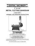
1. Pump: use a ground wire and clamp (supplied).
See Fig. 1. Loosen the grounding lug locknut (W)
and washer (X). Insert one end of a 1.5 mm@ (12
ga) minimum ground wire (Y) into the slot in lug (Z)
and tighten the locknut securely. Connect the other
end of the wire to a true earth ground. Order Part
No. 237569 Ground Wire and Clamp.
4. Spray gun: ground through connection to a properly grounded fluid hose and pump.
5. Fluid supply container: follow your local code.
6. Object being sprayed: follow your local code.
7. Solvent pails used when flushing: follow your local
code. Use only metal pails, which are conductive,
placed on a grounded surface. Do not place the
pail on a nonconductive surface, such as paper or
cardboard, which interrupts the grounding continuity.
W
X
Y
Z
0864
Fig. 1
3. Air compressor: follow manufacturer’s recommendations.
8. To maintain grounding continuity when flushing or
relieving pressure, hold a metal part of the spray
gun firmly to the side of a grounded metal pail,
then trigger the gun.
308213
7
Troubleshooting the Air Motor
Preventive Maintenance Schedule
The operating conditions of your particular system
determine how often maintenance is required. Establish a preventive maintenance schedule by recording
when and what kind of maintenance is needed, and
then determine a regular schedule for checking your
system.
Air Motor Cylinder
Premier motors require lubrication and continuous
maintenance including the replacement of the air motor
cylinder casting at least every 15,000,000 cycles of
use. Use Premier cylinder repair kit 16P239.
Repair or replace the Air Valve assembly (222799)
whenever motor stalling or hesitation occurs. This
ensures the motor does not overtravel and cause
added stress to the cylinder casting.
WARNING
EXPLOSION HAZARD
Without proper maintenance, the cylinder casting (120026) may fracture
unexpectedly due to metal fatigue. This
is a potentially hazardous condition and
may result in serious injury. The precise
life of this casting is difficult to predict
and is affected by the operating pressure, number
of cycles, lubrication and air valve maintenance.
Checking the Air Motor for Leaks
or Damaged Parts
If the pump is not performing well, the problem could
be in the air motor. To check the air motor, perform the
following steps.
1. Close the bleed-type master air valve. Disconnect
the air line.
2. Remove the shroud. Refer to page 11.
8
308213
3. Reinstall the air inlet fitting (22). Reconnect the air
line.
4. Open the bleed-type master air valve and set the
air regulator to about 0.1 MPa, 1 bar (14 psi).
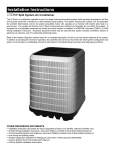
Observe the rocker arms and trip rods for smooth
operation. Check at points A through E in Fig. 2 by
listening or feeling for escaping air, or squirting a
small amount of oil around the suspected leak.
The oil will bubble if air is leaking. Refer to the
sections noted in the Check Chart for detailed
service procedures.
Check Chart
NOTE: Service the air valve every 3 million cycles. If
the air motor stalls, service the air valve immediately.
Ref.
Letter
Problem
Refer to:
A
Rocker assemblies Service rocker arms
(29) not operating.
(see pages 17 and
18).
B
Air escaping around Service trip rod
trip rod or push rods. and air valve
(see pages 11–16).
Service push rod
seals (see pages 17
and 18).
C
Air escaping around Service air valve
air valve (25).
and air valve gaskets
(see pages 11–16).
D
Air escaping around Service slide blocks
or out of exhaust
and air valve seals
manifold (45).
(see pages 11–16).
E
Air escaping around Service piston and
piston rod (4).
rod seals (see pages
19 and 20).
F
Air motor stalls.
Service air valve (see
the NOTE above, and
refer to pages 11–16).
Install the detent, trip
rod, and air valve kits
(see pages 21–24).
22
29 (under the cover)
C (25), F
A, B
(4) E
(45) D
Fig. 2
29
A, B
06547A
308213
9
Service
Pressure Relief Procedure
WARNING
SKIN INJECTION HAZARD
The system pressure must be manually
relieved to prevent the system from
starting or spraying accidentally. Fluid
under high pressure can be injected through the
skin and cause serious injury. To reduce the risk of
an injury from injection, splashing fluid, or moving
parts, follow the Pressure Relief Procedure
whenever you:
D
D
D
D
are instructed to relieve the pressure,
stop spraying/dispensing,
check or service any of the system equipment,
or install or clean the spray tips/nozzles.
1. Lock the gun/valve trigger safety.
Required Service Tools
D Phillips screwdriver
D Flat blade screwdriver
D 16 mm box wrench
D Set of metric socket wrenches
D Set of metric allen wrenches
D Set of adjustable wrenches
D Torque wrench
2. Shut off the air supply to the pump.
3. Close the bleed-type master air valve (required in
your system).
4. Unlock the gun/valve trigger safety.
5. Hold a metal part of the gun/valve firmly to the side
of a grounded metal pail, and trigger the gun/valve
to relieve pressure.
6. Lock the gun/valve trigger safety.
7. Open the drain valve (required in your system)
and/or pump bleeder valve, having a container
ready to catch the drainage.
8. Leave the drain valve open until you are ready to
spray/dispense again.
If you suspect that the spray tip/nozzle or hose is
completely clogged, or that pressure has not been fully
relieved after following the steps above, very slowly
loosen the tip guard retaining nut or hose end coupling
and relieve pressure gradually, then loosen completely.
Now clear the tip/nozzle or hose.
10
308213
D Pliers
D Rubber mallet
D O-ring pick
D Soft brush (for cleaning)
D Large vise, with soft jaws
D Thread sealant
D Thread lubricant
D Multi-purpose grease
D Heavy-duty lithium grease (for air valve)
Service
WARNING
To avoid serious injury and equipment
damage, do not lift the equipment by the
Premier air motor lift ring if the total
weight of the equipment exceeds 550 lb
(250 kg). The lift ring cannot support that
weight.
Air Motor Shroud
NOTE: Reference numbers and letters in parentheses
in the text refer to the callouts in the figures and the
parts drawing.
Air Valve Replacement
NOTE: Service the air valve every 3 million cycles. If
the air motor stalls, service the air valve immediately.
To replace the entire air valve assembly, order Part
No. 222799 and perform the following procedure. To
service the air valve, refer to pages 13–16.
NOTE: Air Valve Repair Kit 222959 includes the subplate seals (27{) and gasket (26{).
WARNING
Disassembly
WARNING
To reduce the risk of serious injury whenever you
are instructed to relieve pressure, always follow the
Pressure Relief Procedure on page 10.
1. Stop the pump at the middle of its stroke. Relieve
the pressure before performing any service.
2. Disconnect the air supply and the ground wire.
3. If necessary, disconnect the displacement pump
from the air motor, as explained in your separate
pump manual.
4. Unscrew the air inlet swivel (22). See Fig. 3.
5. Remove the three screws (13) and washers (51).
Lift the shroud (53) off the motor.
Reassembly
1. Make sure the rocker arm cover pad (63) and
cover plug (57) are in place.
2. Place the shroud (53) on the motor so the three
notches in the top center align with the outer holes
in the lift ring (3). Apply sealant to the three screws
(13) and attach the shroud to the lift ring with the
screws and washers (51).
3. Install the air inlet swivel (22).
To reduce the risk of serious injury whenever you
are instructed to relieve pressure, always follow the
Pressure Relief Procedure on page 10.
1. Stop the pump at the middle of its stroke. Relieve
the pressure before performing any service.
2. Remove the air motor shroud as described under
Air Motor Shroud Disassembly, at left.
3. Use a 6 mm allen wrench to remove the six socket
screws (28) holding the air valve (25) to the motor.
Remove the air valve.
4. Inspect the subplate gasket (26{) and seals (27{)
for wear or damage. Always replace the gasket
(26{) when replacing the air valve. Grease the
grooves of the slide plates (G), then install the
seals (27{) in the grooves with the curved sides
facing out (see the Detail in Fig. 3).
5. Grease the ends of the trip rod (106).
6. Install the new air valve (25), using a 6 mm allen
wrench and the six socket screws (28). Torque to
22–23 NSm (195–205 in-lb).
4. If the displacement pump was removed, reconnect
it as explained in your separate pump manual.
5. Reconnect the air supply and the ground wire.
7. Reinstall the air motor shroud as described under
Air Motor Shroud Reassembly, at left.
308213
11
Service
2
13
51
22
1
Torque to 22–23 NSm (195–205 in-lb)
2
Apply sealant.
3
Grease ends of trip rod.
53
57
{ These parts are included in Air Valve Repair Kit
222959, which may be purchased separately.
Detail of Slide Plate Seals
4
63
5
3
Grease the grooves of
the slide plates (G).
Install the seals (27{) in
the grooves of the slide
plates (G) with the
curved sides facing out.
5
27{
G
4
02301
G
27{
26{
106{
3
28
1
25
06549A
Fig. 3
12
308213
Service
Air Valve Service
2. Remove the air motor shroud as described under
Air Motor Shroud Disassembly, on page 11.
NOTE: Service the air valve every 3 million cycles. If
the air motor stalls, service the air valve immediately.
3. Follow steps 3 and 4 under Air Valve Replacement on page 11.
NOTE: Air Valve Repair Kit 222959 is available. Parts
included in the kit are marked with a symbol ({). For
the best results, use all the parts in the kit.
NOTE: Trip Rod Kit 222981 and Detent Kit 222982 are
available to replace these complete assemblies. Parts
included in Kit 222981 are marked with a symbol (})
and parts included in Kit 222982 are marked with a
checkmark (n).
Disassembly
WARNING
4. Using a 4 mm allen wrench, remove the socket
screws (104) holding the two slide plates (124) to
the valve housing (101). Lift the slide plates off the
housing, being careful not to scratch the polished
surfaces. Clean the slide plate surfaces and edges
and inspect for damage. See Fig. 4.
5. Lift the valve carriage (111) out of the valve housing (101). The detent assemblies (J) will slide out
of the carriage; be careful not to drop them. Set
them aside.
To reduce the risk of serious injury whenever you
are instructed to relieve pressure, always follow the
Pressure Relief Procedure on page 10.
6. Remove the screws (104) holding the top rod
fitting (103) to the valve housing (101). Turn the
fitting 90_ and remove it. Using an o-ring pick,
remove the seal (102). Repeat for the bottom rod
fitting.
1. Stop the pump at the middle of its stroke. Relieve
the pressure before performing any service.
7. Remove the trip rod assembly (T) from the housing (101). Set it aside.
3
Jn
4
2
104
104
2
103}
1
102}
1
6
102}
1
6
103}
1
104
2
5
124
111
101
1
Lubricate.
2
Apply thread sealant.
3
Grease ends of trip rod (T).
4
Torque to 9 NSm (75 in-lb) and unscrew as needed for plate (124) to be flush with housing (101)
5
Torque to 2–3 NSm (20–30 in-lb)
6
Lips must face into housing (101).
}107
104
5
2
}T
3
} These parts are included in Trip Rod Kit
222981, which may be purchased separately.
n These parts are included in Detent Kit 222982,
which may be purchased separately.
5
02271
Fig. 4
308213
13
Service
8. With your fingers, snap the slide blocks (119) off of
the valve carriage (111) to free the o-rings (120).
Clean and inspect the slide blocks. See Fig. 8.
9. Remove the screws (104) and disassemble the
bearing retainers (122), bearing rollers (121), and
pins (123). Clean and inspect these parts.
10. Clean and inspect the valve carriage (111). Remove and replace the bearings (107}).
NOTE: If you are using Detent Kit 222982, it is not
necessary to disassemble the detents. Just replace the
old detents with the new ones provided in the kit (see
Reassembly, step 9).
a. Hold the detent roller (115) with a pliers while
turning the plunger guide (113) slightly with a
wrench, until the locking tabs of the guide
disengage from the windows in the plunger
(114). See Fig. 5.
b. Use a flatblade screwdriver to pry out the
detent roller (115) and pin (117). See Fig. 8.
14. Inspect the carriage bumpers (128) and replace if
worn or damaged.
Reassembly
1. Install the detent plates (105) on the valve housing
(101). Apply thread sealant and torque the screws
(104) to 9 N.m (75 in-lb). Lubricate the plates with
heavy-duty lithium grease. See Fig. 8.
2. Assemble the trip rod.
NOTE: If you are using Trip Rod Kit 222981, it is not
necessary to assemble the trip rod. Skip steps a
through c, and go to step 3.
113
115
02249
Fig. 5
12. To disassemble the trip rod:
NOTE: If you are using Trip Rod Kit 222981, it is not
necessary to disassemble the trip rod. Just replace the
old trip rod with the new one provided in the kit (see
Reassembly, step 3).
WARNING
MOVING PARTS HAZARD
Use caution when disassembling the trip
rod. The trip rod spring (110) is under
tension. When the trip rod is unscrewed
tension is released, and parts may be projected
through the air with considerable force.
308213
b. Disassemble the trip rod assembly. Inspect the
press-fit bearings (129) in place in the spring
guides (108). Clean and inspect all parts.
13. Inspect the two detent plates (105) in place on the
valve housing (101). Remove if worn or damaged.
11. To disassemble the detents:
14
a. Place the flats of one trip rod (106) in a vise
with soft jaws and unscrew the other trip rod
(106) with a wrench. Be careful not to scratch
the trip rods (106). See Fig. 8.
a. Press fit the bearings (129) flush with the
inside surface of the spring guides (108).
Apply thread sealant to one of the trip rods
(106) and screw the shaft (109) onto the rod.
b. Install the spring guides (108) in the spring
(110), with the flanges facing out. Apply thread
sealant to the second trip rod and slide both
trip rods into the spring guides.
c.
Compress the spring so the shaft (109) and
trip rod engage two or three threads. Place the
flats of one trip rod in a vise with soft jaws.
Use a wrench on the flats of the other rod and
torque to 17–23 NSm (150–200 in-lb).
3. Install the trip rod assembly (T}) in the housing
(101). Grease the ends of the trip rod. See Fig. 4.
4. Lubricate the seal (102{}) and slide it onto the trip
rod (T}) and into the top hole of the housing (101)
with the lips facing into the housing. Lubricate
the rod fitting (103{}) and install in the housing
(see Fig. 4). Apply thread sealant and torque the
screws (104) to 2–3 NSm (20–30 in-lb). Repeat for
the bottom of the housing.
Service
5. Install the bearings (107}) on the valve carriage
(111). Apply thread sealant and torque the screws
(104) to 2–3 NSm (20–30 in-lb).
6. Install the bearing retainers (122) in the recesses
of the valve carriage (111). Apply thread sealant
and torque the screws (104) to 9 NSm (75 in-lb).
Lubricate the pins (123n) and install them in the
bearing rollers (121n). Lubricate the retainers
(122) and install the bearing rollers (121n).
7. Lubricate the o-rings (120{) and install them on
the valve carriage (111). Snap the slide blocks
(119) in place with the lip (K) facing toward the
nearest end of the carriage. Be sure the o-rings do
not roll out or twist. Lubricate the slide blocks.
9. Insert the detent assemblies into the valve carriage
(111) so the detent rollers (115) face out of the
carriage. Set the carriage into the valve housing
(101) so the detent rollers engage the detent
plates (105) on the housing. See Fig. 7.
124
111
Jn
104
2
4
8. Assemble the detents.
115
NOTE: If you are using Detent Kit 222982, it is not
necessary to assemble the detents. Skip steps a and
b, and go to step 9.
a. Lubricate the roller pin (117) and install it in the
detent roller (115). Lubricate the spring (112)
and install in the plunger guide (113). Lubricate
the plunger (114). Push the detent roller and
pin assembly into the plunger.
b. Align the windows in the plunger (114) with the
tabs of the plunger guide (113). Stand the
detent assembly on the workbench and push
down on the plunger guide to seat the roller
(115) in the plunger. Make sure the plunger
tabs lock in the windows. See Fig. 6. Repeat
for the other detent assembly.
2
Apply thread sealant.
4
Torque to 9 NSm (75 in-lb) and unscrew as needed for plate (124) to be flush with housing (101).
n These parts are included in Detent Kit 222982,
which may be purchased separately.
02269
Fig. 7
10. Grease the slide plates (124) and install them in
the valve housing (101), with the o-ring grooves
facing out of the housing. Apply thread sealant and
torque the screws (104) evenly to 9 NSm (75 in-lb),
then unscrew as needed for plates (124) to be
flush with housing (101). See Fig. 7
11. Replace the subplate gasket (26{) and seals
(27{). Grease the o-ring grooves of the slide
plates (G), then install the seals (27{) in the
grooves with the curved sides facing out (see the
Detail in Fig. 3 on page 12).
114
113
12. Install the air valve (25), using a 6 mm allen
wrench and the six socket screws (28). Torque to
22–23 NSm (195–205 in-lb). See Fig. 3.
115
02249
Fig. 6
101
13. Reinstall the air motor shroud as described under
Air Motor Shroud Reassembly, on page 11.
308213
15
Service
WARNING
128
MOVING PARTS HAZARD
Use caution when disassembling the trip
rod. The trip rod spring (110) is under
tension. When the trip rod is unscrewed
tension is released, and parts may be projected
through the air with considerable force.
1
3
106}
9
2
108}
5
104
113n
1
K
10
129}
2
7
112n
124
104
4
1
114n
2
1
2
104
103{}
1
102{}
1
6
110}
117n
1
115n
101
129}
1
8
1
7
105
108}
119
{120
1
109}
1
107}
4
2
106}
104
123n
2
121n 122
1
Lubricate with heavy-duty lithium grease.
2
Apply thread sealant.
3
Grease ends of trip rods (106).
4
Torque to 9 NSm (75 in-lb).
1
102{}
1
103{}
1
5
2
3
1
128
Torque to 2–3 NSm (20–30 in-lb).
6
Lips must face into the housing (101).
7
Press fit flush with the inside surface of the guide (108).
8
Lip (K) must face toward the nearest end of the carriage (111).
9
Torque to 17–23 NSm (150–200 in-lb).
10
Torque to 9 NSm (75 in–lb) and unscrew as needed for
plates (124) to be flush with housing (101).
308213
5
104
5
Fig. 8
16
111
6
9
104
1
2
01346
{ These parts are included in Air Valve Repair Kit 222959,
which may be purchased separately.
} These parts are included in Trip Rod Kit 222981, which
may be purchased separately. The kit also includes the
assembled trip rod.
n These parts are included in Detent Kit 222982, which may
be purchased separately.
Service
Subplate and Rocker Assemblies
NOTE: Air Valve Repair Kit 222959 is available. Parts
included in the kit are marked with a symbol ({). For
the best results, use all the parts in the kit.
Disassembly
10. Remove the two screws (42), the top rod fitting
(20), and the push rod (19) from the motor cap (2).
Using an o-ring pick, pull out the seal (21). Inspect
these parts for wear. Repeat for the bottom push
rod assembly.
Reassembly
WARNING
To reduce the risk of serious injury whenever you
are instructed to relieve pressure, always follow the
Pressure Relief Procedure on page 10.
1. Stop the pump at the middle of its stroke. Relieve
the pressure before performing any service.
2. Follow the steps under Air Motor Shroud Disassembly on page 11.
3. Use an allen wrench to remove the six socket
screws (28) holding the air valve (25) to the subplate (23). See Fig. 3 on page 12. Remove the air
valve.
NOTE: To replace or service the air valve, refer to
pages 11–16.
4. Remove the gasket (26) and the two seals (27).
Inspect these parts for wear or damage.
5. Remove the two screws (13) and washers (51)
holding the bottom cover (61) to the bottom rocker
arm cover (62). See Fig. 9.
6. Remove the pad (63, see Fig. 3 on page 12) from
the top rocker assembly. Hold the stud (30) with a
wrench while unscrewing the nut (33). Pull the stud
(30) out and disassemble the rocker assembly.
Push the sleeve (31) out of the rocker arm (29).
Inspect the rocker arm, sleeve, and bearings (32)
for wear.
7. Disassemble the bottom rocker assembly as
explained in step 6.
8. Using a 17 mm box wrench, remove the capscrew
(43) and gasket (47) holding the exhaust manifold
(45) to the subplate (23). Remove the two liners
(44) from the cavities in the manifold. Check that
the vertical slot (V) in the manifold is clear of dirt or
blockage; clean with a brush or compressed air.
See Fig. 9.
9. Using an allen wrench, unscrew the eight socket
screws (41) holding the subplate (23) to the cylinder (1). Remove the subplate and the gasket (24).
Inspect these parts for wear or damage.
1. Lubricate the seal (21{) and insert it in the motor
cap (2) with the lips facing into the cap. Install
the rod fitting (20{). Grease the end of the push
rod (19) and insert it in the fitting. Apply thread
sealant and torque the screws (42) to 2–3 NSm
(20–30 in-lb). Repeat for the bottom push rod
assembly. See Fig. 9.
2. Place the gasket (24) on the back side of the
subplate (23), aligning the holes in both parts. With
the air inlet port (P) facing up, install the subplate
on the cylinder (1) with the eight socket screws
(41). Torque to 10–12 NSm (90–110 in-lb).
3. Install the two liners (44) in the cavities of the
exhaust manifold (45). Attach the manifold to the
subplate with the gasket (47) and capscrew (43),
using a 17 mm box wrench. Torque to 24–27 NSm
(18–20 ft-lb).
4. Lubricate the sleeve (31) and two bearings (32)
and install them in the rocker arm (29). Position
the rocker arm between the top flanges of the
subplate (23).
5. Note that the rocker arm cover (62) has two tabs
that are off-center. Install the cover so the end with
the two tabs is toward the outside of the subplate
(see Fig. 9). Insert the stud (30) through the cover
and rocker arm, then install the nut (33). Torque to
22–23 NSm (195–205 in-lb). Replace the rocker
arm cover pad (63, see Fig. 3 on page 12).
6. Assemble the bottom rocker assembly as explained in steps 4 and 5. Install the bottom cover
(61) and secure to the rocker arm cover with the
two screws (13) and washers (51).
7. Install the two seals (27{) and the gasket (26{).
See the Detail in Fig. 3 on page 12.
8. Install the air valve (25), using a 6 mm allen
wrench and six socket screws (28). Torque to
22–23 NSm (195–205 in-lb).
9. Follow the steps under Air Motor Shroud Reassembly on page 11.
308213 17
Service
{ These parts are included in Air Valve Repair Kit
222959, which may be purchased separately.
z These parts are included in Premier Cylinder
Rebuild Kit 16P239, which may be purchased
separately.
2
19
8
42
2
20{
21{
2
30z
1
32z
7
32z
1
1
5
1
29z
31z
P
62
1z
33z
46
41
24z
3
4
23
62
V
45
1
Lubricate.
2
Apply sealant.
3
Torque to 22–23 NSm (195–205 in-lb).
4
Torque to 10–12 NSm (90–110 in-lb).
5
Torque to 2–3 NSm (20–30 in-lb).
6
Torque to 24–27 NSm (18–20 ft-lb).
7
Lips must face into motor cap (2).
8
Grease the end of push rods (19).
43
6
44
47
61
51
13
06550A
Fig. 9
18
308213
Service
Piston and Piston Rod Seals
NOTE: Air Motor Repair Kit 222958 is available. Parts
included in the kit are marked with an asterisk (*). For
the best results, use all the parts in the kit.
Disassembly
WARNING
To reduce the risk of serious injury whenever you
are instructed to relieve pressure, always follow the
Pressure Relief Procedure on page 10.
1. Stop the pump at the middle of its stroke. Relieve
the pressure before performing any service.
2. Follow the steps under Air Motor Shroud Disassembly on page 11.
3. Disassemble the subplate and rocker assemblies,
as explained on page 17.
4. Remove the six screws (13), the lift ring (3), and
the o-ring (11*). See Fig. 10.
5. Using a 17 mm socket wrench, remove the fifteen
capscrews (12) holding the motor cap (2) to the
cylinder (1). Lift the motor cap off the cylinder.
Remove and inspect the o-ring (10).
6. Disconnect the air motor from the displacement
pump (see your separate pump manual). Leave
the adapter (R) attached to the piston rod.
7. Using a rubber mallet, drive the piston assembly
(5) out of the cylinder (1). Do not use a hammer.
8. Remove and inspect the piston o-ring (9*). Check
the piston and piston rod for scoring or damage.
Leave the piston rod and adapter (R) assembled
unless any of these parts requires replacement.
9. If it is necessary to disassemble the adapter (R)
from the piston rod, be careful not to scratch the
piston rod. Using adjustable wrenches on the flats
of the piston rod, unscrew it from the adapter (R).
10. Remove the screws (14) and the bottom support
bracket (35). Press the bearing (6), o-ring (11*),
seal (7*) and wiper (8*) out the bottom of the
cylinder (1). Inspect these parts for wear or damage.
11. Check the inner surface of the cylinder (1) for
scoring or other damage.
Reassembly
1. Lubricate the ID of the cylinder (1), using a rag
soaked in grease. See Fig. 10.
2. Lubricate the seals and o-ring (7*, 8*, 11*). The
bottom of the bearing (6) has a narrow o-ring
groove on the outer surface. Install the o-ring (11*)
in this groove. Install the wiper (8*) in the bearing,
so the notch of the wiper faces down, out of the
bearing. At the top of the bearing, install the seal
(7*) so the lips face up, toward the cylinder (1).
3. Press the bearing assembly into the neck of the
cylinder (1) from the bottom until it is seated.
4. Install the bottom support bracket (35). Apply
thread sealant to the screws (14) and torque to
6–7 NSm (55–65 in-lb).
5. If the adapter (R) was disassembled, screw the
piston rod onto the adapter (R). Using adjustable
wrenches on the flats of the piston rod, torque to
318–349 NSm (234–257 ft-lb).
6. Lubricate the o-ring (9*) and install it on the piston
(5).
7. Lubricate the piston rod. Lower the piston assembly into the cylinder (1), carefully sliding the adapter and rod down through the bearing (6).
8. Reconnect the air motor to the displacement pump
(see your separate pump manual).
9. Lubricate the o-ring (10) and install it on the motor
cap (2). Place the motor cap on the cylinder (1) so
the push rod hole (M) is aligned with the flat surface (F) of the cylinder. Attach the cap with the
fifteen capscrews (12), using a 17 mm socket
wrench. Torque to 39–43 NSm (29–32 ft-lb).
10. Lubricate the o-ring (11*) and install it on the
underside of the lift ring (3). Align the lift ring with
the six inner holes in the motor cap, with the
grounding lug (49) positioned as shown. Apply
thread sealant and install the six screws (13).
11. Reassemble the subplate and rocker assemblies,
as explained on page 17.
12. Follow the steps under Air Motor Shroud Reassembly on page 11.
308213
19
Service
13
49
2
3
11*z
5
1
12
2
M
10z
1
5
9*z
1
1
7
R
1z
1
Lubricate.
2
Apply sealant.
3
Notch faces down, out of bearing (6).
4
Torque to 6–7 NSm (55–65 in-lb).
5
Torque to 39–43 NSm (29–32 ft-lb).
6
Lips must face up, toward cylinder (1).
7
Lubricate inside diameter with rag soaked in grease.
9
Torque to 318–349 NSm (234–257 ft-lb).
* These parts are included in Air Motor Repair Kit
222958, which may be purchased separately.
z These parts are included in Premier Cylinder
Rebuild Kit 16P239, which may be purchased
separately.
9
F
7*z
1
6
6
8*z
1
11*z
1
3
35
14
2
4
06551A
Fig. 10
20
308213
Parts
Model 222800 Premier Air Motor, Series C
NOTE: Some parts of this assembly are listed and
pictured on page 22.
51
13
22
57
Ref.
No.
Part No.
Description
3
11*z
13
184353
109484
107558
14
105468
15
22
189977
112955
35
48
49
50
51
53
54
57
60
61
63
64
65
66
191989
104582
104029
190072
108788
276457
113918
111909
158585
120027
192881
192883
192882
100132
RING, lift
O-RING; buna-N
SCREW, cap, hex hd; M8 x 1.25;
25 mm (0.98 in.) long
SCREW, cap, hex hd; M6 x 1;
12 mm (0.47 in.) long
MOUNT; 3/8–16 unc–2A
SWIVEL, air inlet, 90_;
1 in. npt(f) x 1 in. npsm(f)
BRACKET, support
WASHER, grounding
LUG, grounding
GASKET; polyethylene
WASHER, flat; 8 mm
SHROUD, motor
PAD, top
PLUG, button
NIPPLE; 1 in. npt
COVER, bottom
PAD, rocker arm cover
PAD, front
PAD, bottom
WASHER, flat
54
64
53
Y
49
48
13
Qty.
1
1
11
6
3
1
1
1
1
6
5
1
1
1
1
1
1
1
1
3
3
*
11*z
60
These parts are included in Air Motor Repair Kit
222958, which may be purchased separately.
z These parts are included in Premier Cylinder Re-
See page 22
build Kit 16P239, which may be purchased separately.
63
Y Foreign language warning labels are available at no
cost. Order Part No. 290396 (German), 290397
(French), or 290398 (Spanish).
See page 24
66
50
15
65
50
35
14
51
61
13
06548B
308213
21
Parts
NOTE: Some parts of this assembly are listed and pictured on page 21.
12
42
19
2
20{
21{
10z
5
9*z
1z
30z
32z
32z
29
31z
62
24z
33z
23
41
46
46
z*7
27z{n
26z{n
25
44
28
6
z*8
z*11
62
43
45
22
308213
47
01345B
Parts
Model 222800 Premier Air Motor, Series C (shown)
NOTE: Some parts of this assembly are listed and pictured on page 21.
Ref.
No.
Part No.
Description
1z
2
5
6
7*z
8*z
9*z
10z
11*z
12
120026
184374
15B959
184351
109492
109493
109485
109486
109484
109487
19
20{
21{
23
24z
25
184357
276066
109494
184463
184376
222799
CYLINDER, motor
1
CAP, motor
1
PISTON ASSEMBLY
1
BEARING; acetal
1
SEAL, bearing; polyurethane
1
WIPER; polyurethane
1
O-RING; buna-N
1
O-RING; buna-N
1
O-RING; buna-N
1
SCREW, cap, hex hd; M10 x 1.5;
30 mm (1.18 in.) long
15
ROD, push
2
FITTING, rod
2
SEAL, rod; polyurethane
2
SUBPLATE
1
GASKET; cork/rubber
1
VALVE, air motor;
see page 24
1
GASKET; cork/rubber
1
SEAL; buna-N
2
SCREW, cap, socket hd; M8 x 1.25;
50 mm (1.97 in.) long
6
ARM, rocker
2
STUD
2
SLEEVE, rocker arm
2
BEARING, rocker; acetal
4
26{nz184377
27{nz184467
28
109490
29z
30z
31z
32z
184359
110036
184607
184360
Qty.
Ref.
No.
Part No.
Description
33z
105329
41
109489
42
107100
43
109491
44
45
46
47
62
276076
186264
100721
167730
192686
NUT, lock, with nylon insert;
M8 x 1.25
2
SCREW, cap, socket hd; M6 x 1.0;
20 mm (0.79 in.) long
8
SCREW, cap, socket hd; M5 x 0.8;
12 mm (0.47 in.) long
4
SCREW, cap, hex hd; M10 x 1.5;
50 mm (1.97 in.) long
1
LINER; polyurethane
2
MANIFOLD, exhaust
1
PLUG, pipe, socket hd; 1/4–18 npt 3
GASKET, copper
1
COVER, rocker arm
2
Qty.
*
These parts are included in Air Motor Repair Kit
222958, which may be purchased separately.
{
These parts are included in Air Valve Repair Kit
222959, which may be purchased separately.
n These parts are included in Detent Kit 222982,
which may be purchased separately.
z These parts are included in Premier Cylinder Re-
build Kit 16P239, which may be purchased separately.
NOTE: Remote Exhaust Manifold (184559) is available with a 1 in. npt(f) outlet
308213
23
Parts
Part No. 222799 Air Valve, Series A
128
106}
108}
129}
104
n113
104
103{}
n112
124
102{}
n114
104
110}
n117
n115
101
129}
127Y
105
108}
119
{120
109}
107}
106}
104
104
102{}
n123
n121
122
111
104
128
24
308213
103{}
01346
Parts
Part No. 222799 Air Valve, Series A
Ref.
No.
Part No.
Description
101
102{}
103{}
104
184375
109494
276067
107100
105
106}
107}
108}
109}
110}
111
112n
113n
114n
115n
117n
119
120{
276060
184358
276083
184361
184465
184485
184372
184484
276064
184370
184619
184369
184363
109514
HOUSING, valve
1
SEAL, rod; polyurethane
2
FITTING, rod; acetal
2
SCREW, cap, socket hd; M5 x 0.8;
12 mm (0.47 in.) long
24
PLATE, detent
2
ROD, trip
2
BEARING; acetal
2
GUIDE, spring
2
SHAFT
1
SPRING, compression
1
CARRIAGE, valve
1
SPRING, compression
2
GUIDE, plunger; acetal
2
PLUNGER
2
ROLLER, detent
2
PIN, roller
2
BLOCK, slide
2
O-RING; urethane
2
Qty.
Ref.
No.
Part No.
Description
121n
122
123n
124
127Y
128
129}
109513
276068
184605
184362
184614
184615
184603
ROLLER, bearing
RETAINER, bearing
PIN, roller
PLATE, slide
LABEL, caution
BUMPER
BEARING, guide; acetal
Qty.
{
These parts are included in Air Valve Repair Kit
222959, which may be purchased separately.
}
These parts are included in Trip Rod Kit 222981,
which may be purchased separately.
4
4
4
2
2
2
2
n These parts are included in Detent Kit 222982,
which may be purchased separately.
Y Replacement Danger and Warning labels, tags and
cards are available at no cost.
308213
25
Technical Data
Category
Data
Maximum air input pressure
0.7 MPa, 7 bar (100 psi)
Operating pressure range
.07–0.7 MPa, 0.7–7 bar (10–100 psi)
Maximum recommended speed
50 cycles per min
Operating temperature
12.8 to 65.6_C (55 to 150_F)
Air motor piston effective area
800 cm@ (124 in.@)
Air motor piston diameter
321 mm (12.64 in.)
Stroke length
120 mm (4.75 in.)
Air inlet size
1 npsm(f)
Weight
approx. 50 kg (110 lb)
26
308213
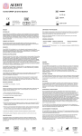
Dimensions
Top View
455 mm
(17.9 in.)
585 mm
(23.0 in.)
06554
1 in.
npsm(f)
Air Inlet
Side View
438.4 mm
(17.3 in.)
158.8 mm
(6.25 in.)
Downstroke
424.5 mm
(16.7 in.)
38.3 mm
(1.5 in.)
Upstroke
06553
135.0 mm
(5.3 in.)
67.5 mm
(2.7 in.)
116.9 mm
(4.6 in.)
Bottom View
87.9 mm
(3.5 in.)
Three M16 x 2.0 Holes
Three 3/8–16 Mounting Studs
101.5 mm
(4.0 in.)
50.7 mm
(2.0 in.)
06555
308213
27
Graco Standard Warranty
Graco warrants all equipment manufactured by Graco and bearing its name to be free from defects in material and workmanship on the
date of sale to the original purchaser for use. With the exception of any special, extended, or limited warranty published by Graco,
Graco will, for a period of twelve months from the date of sale, repair or replace any part of the equipment determined by Graco to be
defective. This warranty applies only when the equipment is installed, operated and maintained in accordance with Graco’s written
recommendations.
This warranty does not cover, and Graco shall not be liable for general wear and tear, or any malfunction, damage or wear caused by
faulty installation, misapplication, abrasion, corrosion, inadequate or improper maintenance, negligence, accident, tampering, or substitution of non–Graco component parts. Nor shall Graco be liable for malfunction, damage or wear caused by the incompatibility of
Graco equipment with structures, accessories, equipment or materials not supplied by Graco, or the improper design, manufacture,
installation, operation or maintenance of structures, accessories, equipment or materials not supplied by Graco.
This warranty is conditioned upon the prepaid return of the equipment claimed to be defective to an authorized Graco distributor for
verification of the claimed defect. If the claimed defect is verified, Graco will repair or replace free of charge any defective parts. The
equipment will be returned to the original purchaser transportation prepaid. If inspection of the equipment does not disclose any defect
in material or workmanship, repairs will be made at a reasonable charge, which charges may include the costs of parts, labor, and
transportation.
THIS WARRANTY IS EXCLUSIVE, AND IS IN LIEU OF ANY OTHER WARRANTIES, EXPRESS OR IMPLIED, INCLUDING BUT
NOT LIMITED TO WARRANTY OF MERCHANTABILITY OR WARRANTY OF FITNESS FOR A PARTICULAR PURPOSE.
Graco’s sole obligation and buyer’s sole remedy for any breach of warranty shall be as set forth above. The buyer agrees that no other
remedy (including, but not limited to, incidental or consequential damages for lost profits, lost sales, injury to person or property, or any
other incidental or consequential loss) shall be available. Any action for breach of warranty must be brought within two (2) years of the
date of sale.
Graco makes no warranty, and disclaims all implied warranties of merchantability and fitness for a particular purpose in connection
with accessories, equipment, materials or components sold but not manufactured by Graco. These items sold, but not manufactured
by Graco (such as electric motors, switches, hose, etc.), are subject to the warranty, if any, of their manufacturer. Graco will provide
purchaser with reasonable assistance in making any claim for breach of these warranties.
In no event will Graco be liable for indirect, incidental, special or consequential damages resulting from Graco supplying equipment
hereunder, or the furnishing, performance, or use of any products or other goods sold hereto, whether due to a breach of contract,
breach of warranty, the negligence of Graco, or otherwise.
FOR GRACO CANADA CUSTOMERS
The parties acknowledge that they have required that the present document, as well as all documents, notices and legal proceedings
entered into, given or instituted pursuant hereto or relating directly or indirectly hereto, be drawn up in English. Les parties reconnaissent avoir convenu que la rédaction du présente document sera en Anglais, ainsi que tous documents, avis et procédures judiciaires
exécutés, donnés ou intentés à la suite de ou en rapport, directement ou indirectement, avec les procedures concernées.
Graco Information
TO PLACE AN ORDER, contact your Graco distributor, or call one of the following numbers
to identify the distributor closest to you:
1–800–328–0211 Toll Free
612–623–6921
612–378–3505 Fax
All written and visual data contained in this document reflects the latest product information available at the time of publication.
Graco reserves the right to make changes at any time without notice.
For patent information, see www.graco.com/patents.
Original instructions. This manual contains English. MM 308213
Graco Headquarters: Minneapolis
International Offices: Belgium, China, Japan, Korea
GRACO INC. AND SUBSIDIARIES S P.O. BOX 1441 S MINNEAPOLIS MN 55440–1441 S USA
28
Copyright 1993, Graco Inc. All Graco manufacturing locations are registered to ISO 9001.
www.graco.com
Revision V, March 2014
308213