1
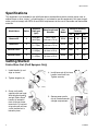
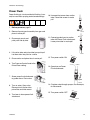
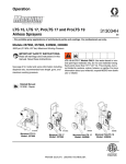
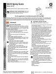
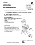
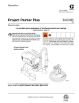
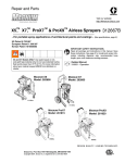
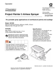
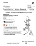
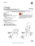
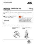
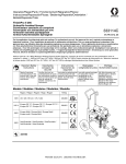
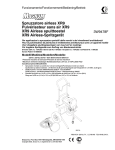
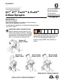
Operation
X5™
, X7™
, ProX7™ & ProX9™
Airless Sprayers
US Patent 6,752,067
European Patent 1 208 287
Korean Patent 10-0668583
Taiwan Patent No. D124860 for "Pro X7 Airless Paint Sprayer (Design)"
Chinese Patent ZL200730154436.7 for Pro X7
The manual provided with
this sprayer contains
English and Español.
Visit our website;
http://MAGNUM.Graco.com
312001G
- For portable spray applications of architectural paints and coatings (Specifications, page 2.)
IMPORTANT SAFETY INSTRUCTIONS.
Read all warnings and instructions in this
manual. Save these instructions. See page
2 for model and series information including
dispense rate, recommended hose length,
guns, and maximum working pressure.
X5 & X7 Models ONLY: Use water-based or
mineral spirit-type materials only. Do not use
materials having flash points lower than 70° F
(21° C). For more information about your
material, request MSDS from distributor or
retailer.
MAGNUM X5
Model: 262800
ti11304a
MAGNUM X7
Model: 262805
MAGNUM ProX7
Model: 261815
ti11305a
ti9369a
Graco Inc. P.O. Box 1441 Minneapolis, MN 55440-1441
Copyright 2007, Graco Inc. is registered to I.S. EN ISO 9001
MAGNUM ProX9
Model: 261820
ti9368a
Specifications
Specifications
This equipment is not intended for use with flammable or combustible materials used in places such as
cabinet shops or other “factory”, or fixed locations. If you intend to use this equipment in this type of application, you must comply with NFPA 33 and OSHA requirements for the use of flammable and combustible
materials.
Model Name
Series
Dispense
Rate gpm
(lpm)
Hose Length and
Diameter
Maximum Working
Pressure
Gun
Model
PSI
MPa
bar
MAGNUM X5
A
0.24 gpm
(0.91 lpm)
1/4 in. x 25 ft
(6.4 mm x 7.5 m)
SG10
2800
19
193
MAGNUM X7
A
0.31 gpm
(1.17 lpm)
1/4 in. x 25 ft
(6.4 mm x 7.5 m)
SG10
3000
21
207
MAGNUM ProX7
A
0.34 gpm
(1.29 lpm)
1/4 in. X 50 ft
(6.4 mm x 15 m)
SG20
3000
21
207
MAGNUM ProX9
A
0.38 gpm
(1.44 lpm)
1/4 in. X 50 ft
(6.4 mm x 15 m)
SG20
3000
21
207
Getting Started
Fold-n-Store Cart (ProX Sprayers Only)
1. Unfold handle (a) and
align as shown.
d
a
4. Install hose rack (d) to frame
handle. Install lock nuts.
Tighten securely.
2. Tighten wingnuts (b).
b
3. Grasp cart handle
securely with one hand.
With the other hand lift
and pull Fold-n-Store™
handle (a) located in
front of sprayer frame,
toward you. Lift up front
of sprayer until you hear
a click and the cart is
locked in place.
ti9675a
ti9369a
5. Secure power cord in
clip (e) located beneath
storage compartment.
c
ti9679a
e
2
ti9719a
312001G
Warnings
Warnings
The following warnings are for the setup, use, grounding, maintenance and repair of this equipment. The
exclamation point symbol alerts you to a general warning and the hazard symbol refers to procedure-specific risks. Refer back to these warnings. Additional, product-specific warnings may be found throughout
the body of this manual where applicable.
Grounding Instructions
This product must be grounded. In the event of an electrical short circuit, grounding reduces the risk of
electric shock by providing an escape wire for the electric current. This product is equipped with a cord
having a grounding wire with an appropriate grounding plug. The plug must be plugged into an outlet that
is properly installed and grounded in accordance with all local codes and ordinances.
WARNING
GROUNDING
• Improper installation of the grounding plug is able to result in a risk of electric shock.
• When repair or replacement of the cord or plug is required, do not connect the grounding wire
to either flat blade terminal.
• The wire with insulation having an outer surface that is green with or without yellow stripes is
the grounding wire.
• Check with a qualified electrician or serviceman when the grounding instructions are not completely understood, or when in doubt as to whether the product is properly grounded.
• Do not modify the plug provided; if it does not fit the outlet, have the proper outlet installed by
a qualified electrician.
• This product is for use on a nominal 120V circuit and has a grounding plug similar to the plug
illustrated in the figure below.
ti9164a
•
•
Only connect the product to an outlet having the same configuration as the plug.
Do not use an adapter with this product.
Extension Cords:
• Use only a 3-wire extension cord that has a 3-blade grounding plug and a 3-slot receptacle
that accepts the plug on the product.
• Make sure your extension cord is not damaged. If an extension cord is necessary, use 12
AWG
(2.5 mm2) minimum to carry the current that the product draws.
An undersized cord results in a drop in line voltage and loss of power and overheating.
312001G
3
Warnings
WARNING
FIRE AND EXPLOSION HAZARD
Flammable fumes, such as solvent and paint fumes, in work area can ignite or explode. To help
prevent fire and explosion:
• Do not spray flammable or combustible materials near an open flame or sources of ignition
such as cigarettes, motors, and electrical equipment. For X5 and X7 models: only use
water-based or mineral spirit-type materials with a flash point greater than 70° F (21° C).
• Paint or solvent flowing through the equipment is able to result in static electricity. Static electricity creates a risk of fire or explosion in the presence of paint or solvent fumes. All parts of
the spray system, including the pump, hose assembly, spray gun, and objects in and around
the spray area shall be properly grounded to protect against static discharge and sparks. Use
Graco conductive or grounded high-pressure airless paint sprayer hoses.
• Verify that all containers and collection systems are grounded to prevent static discharge.
• Connect to a grounded outlet and use grounded extensions cords. Do not use a 3-to-2
adapter.
• Do not use a paint or a solvent containing halogenated hydrocarbons.
• Keep spray area well-ventilated. Keep a good supply of fresh air moving through the area.
Keep pump assembly in a well ventilated area. Do not spray pump assembly.
• Do not smoke in the spray area.
• Do not operate light switches, engines, or similar spark producing products in the spray area.
• Keep area clean and free of paint or solvent containers, rags, and other flammable materials.
• Know the contents of the paints and solvents being sprayed. Read all Material Safety Data
Sheets (MSDS) and container labels provided with the paints and solvents. Follow the paint
and solvents manufacturer’s safety instructions.
• Fire extinguisher equipment shall be present and working.
• Sprayer generates sparks. When flammable liquid is used in or near the sprayer or for flushing
or cleaning, keep sprayer at least 20 feet (6 m) away from explosive vapors.
SKIN INJECTION HAZARD
• Do not aim the gun at, or spray any person or animal.
• Keep hands and other body parts away from the discharge. For example, do not try to stop
leaks with any part of the body.
• Always use the nozzle tip guard. Do not spray without nozzle tip guard in place.
• Use Graco nozzle tips.
• Use caution when cleaning and changing nozzle tips. In the case where the nozzle tip clogs
while spraying, follow the Pressure Relief Procedure for turning off the unit and relieving the
pressure before removing the nozzle tip to clean.
• Do not leave the unit energized or under pressure while unattended. When the unit is not in
use, turn off the unit and follow the Pressure Relief Procedure for turning off the unit.
• High-pressure spray is able to inject toxins into the body and cause serious bodily injury. In the
event that injection occurs, get immediate surgical treatment.
• Check hoses and parts for signs of damage. Replace any damaged hoses or parts.
• This system is capable of producing 3000 psi. Use Graco replacement parts or accessories
that are rated a minimum of 3000 psi.
• Always engage the trigger lock when not spraying. Verify the trigger lock is functioning properly.
• Verify that all connections are secure before operating the unit.
• Know how to stop the unit and bleed pressure quickly. Be thoroughly familiar with the controls.
4
312001G
Warnings
WARNING
EQUIPMENT MISUSE HAZARD
Misuse can cause death or serious injury.
• Always wear appropriate gloves, eye protection, and a respirator or mask when painting.
• Do not operate or spray near children. Keep children away from equipment at all times.
• Do not overreach or stand on an unstable support. Keep effective footing and balance at all
times.
• Stay alert and watch what you are doing.
• Do not operate the unit when fatigued or under the influence of drugs or alcohol.
• Do not kink or over-bend the hose.
• Do not expose the hose to temperatures or to pressures in excess of those specified by Graco.
• Do not use the hose as a strength member to pull or lift the equipment.
ELECTRIC SHOCK HAZARD
Improper grounding, setup, or usage of the system can cause electric shock.
• Turn off and disconnect power cord before servicing equipment.
• Use only grounded electrical outlets.
• Use only 3-wire extension cords.
• Ensure ground prongs are intact on sprayer and extension cords.
• Do not expose to rain. Store indoors.
PRESSURIZED ALUMINUM PARTS HAZARD
Do not use 1, 1, 1-trichloroethane, methylene chloride, other halogenated hydrocarbon solvents or
fluids containing such solvents in pressurized aluminum equipment. Such use can cause serious
chemical reaction and equipment rupture, and result in death, serious injury, and property damage.
BURN HAZARD
Equipment surfaces can become very hot during operation. To avoid severe burns, do not touch
hot equipment. Wait until equipment has cooled completely.
MOVING PARTS HAZARD
Moving parts can pinch or amputate fingers and other body parts.
• Keep clear of moving parts.
• Do not operate equipment with protective guards or covers removed.
• Pressurized equipment can start without warning. Before checking, moving, or servicing
equipment, follow the Pressure Relief Procedure in this manual. Disconnect power or air
supply.
TOXIC FLUID OR FUMES HAZARD
Toxic fluids or fumes can cause serious injury or death if splashed in the eyes or on skin, inhaled,
or swallowed.
• Read MSDS’s to know the specific hazards of the fluids you are using.
• Store hazardous fluid in approved containers, and dispose of it according to applicable guidelines.
PERSONAL PROTECTIVE EQUIPMENT
You must wear appropriate protective equipment when operating, servicing, or when in the operating area of the equipment to help protect you from serious injury, including eye injury, inhalation of
toxic fumes, burns, and hearing loss. This equipment includes but is not limited to:
• Protective eye wear
• Clothing and respirator as recommended by the fluid and solvent manufacturer
• Gloves
• Hearing protection
312001G
5
Installation
Installation
Grounding and Electric
Requirements
Smaller gauge or longer extension cords may
reduce sprayer performance.
Sprayer must be grounded. Grounding reduces
the risk of static and electric shock by providing an
escape wire for electrical current due to static build
up or in the event of a short circuit.
• The 120 Vac sprayers require a 120
Vac, 60 Hz, 15A circuit with a grounding receptacle.
•
•
•
Never use an outlet
that is not grounded
or an adapter.
ti5573a
ti9207a
Do not use the sprayer if the
electrical cord has a damaged ground prong.
Only use an extension cord
with an undamaged 3-prong
plug.
Thermal Overload
ti5572a
Recommended extension cords for use with
this sprayer:
• 50 ft (15.0 m) 14 AWG (2.1 mm2)
• 100 ft (30.0 m) 12 AWG (3.3 mm2)
Spray gun: ground through connection to a properly grounded fluid hose and pump.
6
Fluid supply container: follow local code.
Solvent pails used when flushing: follow local
code. Use only conductive metal pails, placed on a
grounded surface such as concrete. Do not place
the pail on a nonconductive surface, such as paper
or cardboard, which interrupts grounding continuity.
Grounding the metal pail: connect a ground wire
to the pail by clamping one end to pail and other
end to ground such as a water pipe.
Maintaining grounding continuity when flushing or
relieving pressure: hold
metal part of the spray gun
firmly to the side of a
grounded metal pail, then
trigger the gun.
Motor has a thermal overload switch to shut itself
down if overheated. If unit overheats, allow approximately 45 minutes for unit to cool. Once cool,
switch will close and unit will restart.
To reduce risk of injury from motor starting unexpectedly when it cools, always turn power switch
OFF if motor shuts down.
312001G
Component Identification
Component Identification
A
Airless spray gun
Dispenses fluid.
B
Power switch
Turns sprayer ON and OFF.
C
Pressure control knob
Increases (clockwise) and decreases (counter-clockwise) fluid pressure
in pump, hose, and spray gun.
C1
Setting Indicator
To select function, align symbol on pressure control knob with setting
indicator, page 9.
D
Pump fluid outlet fitting
Threaded connection for paint hose.
InstaClean™ fluid filter
(ProX Sprayers Only)
•
E
•
Filters fluid coming out of pump to reduce tip plugging and improve
finish.
Self cleans only during pressure relief.
F
ProX Power-Piston™
Pump (behind Easy
Access door, not shown)
(ProX Sprayers Only)
Pumps and pressurizes fluid and delivers it to paint hose.
F1
Easy Access door
(ProX Sprayers Only)
Easy Access door permits quick access to outlet valve. To remove door,
insert flat blade of screwdriver into slot on the bottom of the door (as
shown on page, 7).
G
Suction tube
Draws fluid from paint pail into pump.
H
Prime tube (with diffuser)
Drains fluid in system during priming and pressure relief.
J
Prime/Spray valve
•
•
•
In PRIME position (pointing down) directs fluid to prime tube.
In SPRAY position (pointing forward) directs pressurized fluid to
paint hose.
Automatically relieves system pressure in overpressure situations.
K
Storage compartment
(ProX Sprayers Only)
Provides onboard storage for spray tips and/or tools.
L
Inlet screen
Prevents debris from entering pump.
M
Paint hose
Transports high-pressure fluid from pump to spray gun.
N
Fold-n-Store™ Handle
(ProX Sprayers Only)
Used to fold cart frame for hanging on wall.
Q
Tip guard
Reduces risk of fluid injection injury.
•
R
Reversible spray tip
•
Atomizes fluid being sprayed, forms spray pattern and controls fluid
flow according to hole size.
Reverse unclogs plugged tips without disassembly.
S
Gun trigger safety lever
(page 9)
Prevents accidental triggering of spray gun.
T
Gun fluid inlet fitting
Threaded connection for paint hose.
U
Power Flush attachment
Connects garden hose to suction tube for power flushing water-base
fluids.
V
Gun fluid filter
Filters fluid entering spray gun to reduce tip clogs.
W
Hose wrap Rack
Stows paint hose. (X7, ProX7, and ProX9 only)
X
Pail hanger
(X7, Prox7, and ProX9)
For transporting pail by its handle.
AA
QuickAccess™ Inlet
Permits quick access to inlet valve to clear debris (ProX9 only).
312001G
7
Component Identification
ti9724a
U
ti9346a
B
W
K
J
F1
F
ti9670a
N
X
H
C
C1
G
ti9368a
AA
ti9669a
E
D
L
R
Q
S
V (SG20)
A
V (SG10)
T
M
8
ti9668a
ti11455a
ti9667a
312001G
Operation
Operation
Trigger Lock
Always engage the trigger lock when you stop
spraying to prevent the gun from being triggered
accidentally by hand or if dropped or bumped.
2. Turn Prime/Spray valve to
PRIME to relieve pressure.
ti9346a
ti8922a
ti8923a
Trigger Locked (SG10)
3. Hold gun firmly to
side of pail. Trigger
the gun to relieve
pressure.
Trigger Unlocked (SG10)
ti9207a
4. Engage trigger
lock.
ti8908a
ti8909a
ti8923a
ti8908a
Trigger Locked (SG20)
Trigger Unlocked (SG20)
Pressure Relief Procedure
Follow this Pressure Relief Procedure whenever
you stop spraying and before cleaning, checking,
servicing, or transporting equipment.
1. Turn power switch OFF and unplug
power cord.
(SG10)
(SG20)
Leave Prime/Spray valve in the PRIME
position until you are ready to spray again.
If you suspect the spray tip or hose is clogged or
that pressure has not been fully relieved after following the steps above, VERY SLOWLY loosen tip
guard retaining nut or hose end coupling to relieve
pressure gradually, then loosen completely. Clear
hose or tip obstruction. Read Unclogging Spray
Tip, page 13.
ti2810a
Pressure Control Knob Settings
ti5597a
High Pressure
Spray
Low Pressure Prime/ Rolling
Spray
Clean
To select function, align symbol on pressure control knob with setting indicator on sprayer.
312001G
9
Setup
Setup
Prime and Flush Storage Fluid
1. Unscrew tip and guard
assembly from gun.
ti9714a
Before you use your sprayer for the first time or begin a
new spraying project, you need to prime the sprayer and
flush the storage fluid out of the sprayer.
2. Uncoil hose and connect
one end to gun. Use two
wrenches to tighten
securely
Oil- or Water-based Materials
ti9681a
3. Connect other
end of hose to
sprayer.
ti11456a
(X5 & X7)
To spray lacquers with the ProX7 or ProX9,
you must purchase lacquer conversion kit
256212, and follow priming procedure for
oil-based materials. The X5 and X7 units are
not intended for lacquers.
•
When spraying water-based materials,
flush the system thoroughly with water.
•
When spraying oil-based materials, flush
the system thoroughly with mineral spirits
or compatible, oil-based flushing solvent.
•
To spray water-based materials after
spraying oil-based materials, flush the
system thoroughly with water first. The
water flowing out of prime tube should be
clear and solvent-free before you begin
spraying the water-based material.
•
To spray oil-based materials after spraying water-based materials, flush the system thoroughly with mineral spirits or a
compatible oil-based flushing solvent first.
The solvent flowing out of the prime tube
should not contain any water.
•
When flushing with solvents, ground pail
and gun. Read Grounding and Electric
Requirements, page 6.
•
To avoid fluid splashing back on your skin
or into your eyes, always aim gun at inside
wall of pail.
ti9674a
(ProX7 & ProX9)
If hose is already connected, make sure
connections are tight.
4. Turn OFF power switch.
ti2810a
5. Turn Pressure Control Knob
all the way left
(counter-clockwise) to
minimum pressure.
ti9344a
1. Make sure the power switch is
OFF and the sprayer is
unplugged.
ti2810a
10
312001G
Setup
2. Separate prime tube (smaller)
from suction tube (larger).
10. Turn power switch OFF.
ti2810a
ti2039a
3. Place prime tube in waste
pail.
11. Transfer suction tube to
paint pail and submerge
suction tube in paint.
ti9653a
12. Turn power switch ON.
ti9652a
ti5580a
4. Submerge suction tube in
water or flushing solvent.
13. When you see
paint coming out
of prime tube:
ti9651a
5. Turn Prime/Spray Valve to
PRIME.
a. Point gun into
waste pail.
b. Unlock gun
trigger lock.
ti9346a
c. Pull and hold
gun trigger.
d. Turn
Prime/Spray
valve to
SPRAY.
6. Plug sprayer in a grounded outlet.
7. Turn power switch ON.
ti5580a
ti8909a
(SG10)
(SG20)
ti9345a
14. Continue to trigger gun into waste pail until you
see only paint coming out of gun.
15. Release trigger.
Engage trigger
lock.
8. Align setting indicator with
Prime/Clean setting on
Pressure Control knob until
pump starts, page 9.
ti8923a
ti9718a
9. When sprayer starts pumping, flushing solvent
and air bubbles will be purged from system.
Allow fluid to flow out of prime tube, into waste
pail, for 30 to 60 seconds.
16. Transfer prime
ti8908a
tube to paint
(SG10)
(SG20)
pail and clip
prime tube to
suction tube.
• Motor stopping indicates pump and hose
are primed with paint.
•
312001G
ti8922a
If motor continues to run the sprayer is not
properly primed. To reprime repeat step 8.
11
Setup
Install Tip and Guard on Gun
Spraying Techniques
Preventing Excessive Tip Wear
•
Spray should be atomized (evenly distributed,
no gaps at edges). Start at low pressure setting, increase pressure a little at a time until you
see a good spray pattern, without tails.
•
Spray at lowest pressure that atomizes paint.
•
If maximum sprayer pressure is not enough for
a good spray pattern, tip is too worn. See
Reversible Spray Tip Selection Chart, page 15.
1. Engage trigger lock.
ti8908a
ti8923a
(SG10)
(SG20)
2. Verify tip and guard parts are assembled in
order shown.
retaining nut
black rubber gasket and
metal seat
tails-gaps
at edges
good
spray pattern
pressure
too low
guard
ti5592a
ti8911a
tip
Use tip to align seat
in guard
If tails persist when spraying at the highest
pressure, a smaller tip is needed or the
material may need to be thinned.
Tip must be pushed
all the way into guard
Adjust Spray Pressure
ti9574a
ti5606a
3. Screw tip and guard assembly
on gun. Tighten retaining nut.
This sprayer is set up for most airless spraying
applications. Details on tip selection, tip wear, coat
thickness, etc. are provided on page 14.
Motor only runs when gun is triggered. Sprayer
is designed to stop pumping when gun trigger
is released.
ti9313a
Align setting indicator with function symbol on
Pressure Control knob, page 9.
12
•
Turning knob to right (clockwise), increases
pressure at gun.
•
Turning it left (counter-clockwise), decreases
pressure.
•
General spraying instructions are provided in
Getting Started with Basic Spraying Techniques section of this manual, page 16.
312001G
Setup
Unclogging Spray Tip
To avoid fluid splashback:
• Never pull gun trigger when arrow-shaped handle is between SPRAY and UNCLOG positions.
•
Tip must be pushed all the way into guard.
1. To UNCLOG
tip obstruction,
engage trigger
lock.
4. Unlock
trigger
lock. Pull
trigger to
clear clog.
ti8922a
ti8909a
(SG10)
(SG20)
5. When obstruction is
cleared, engage trigger
lock and rotate
arrow-shaped handle
back to SPRAY position.
ti8923a
ti9049a
ti8908a
(SG10)
(SG20)
Point the arrow-shaped handle on the spray tip
forward to SPRAY and backward to UNCLOG
obstructions.
2. Point arrow-shaped
handle backward to
UNCLOG position.
3. Aim gun at piece of
scrap or cardboard.
ti9048a
312001G
13
Setup
Tip Selection
Selecting Tip Hole Size
Tips come in a variety of hole sizes for spraying a
range of fluids. Your sprayer includes an 0.015 in
(0.38 mm) tip for use in most spraying applications.
Use the following table to determine the range of
recommended tip hole sizes for each fluid type. If
you need a tip other than the one supplied, see the
Reversible Tip Selection Chart on page 15.
•
Maximum tip hole sizes supported by the
sprayer:
– X5: 0.015 in. (0.38 mm)
– X7: 0.017 in. (0.43 mm)
– ProX7: 0.017 in. (0.43 mm)
– ProX9: 0.019 in. (0.48 mm)
HINTS:
• As you spray, the tip wears and enlarges. Starting with a tip hole size smaller than the maximum will allow you to spray within the rated
flow capacity of the sprayer.
Coatings
Tip Hole Size
Stains
0.011 in. (0.28 mm)
✔
0.013 in. (0.33 mm)
✔
0.015 in. (0.38 mm)
Enamels
Primers
Interior Paints
✔
✔
✔
✔
✔
✔
✔
✔
✔
✔
0.017 in. (0.43 mm)
Exterior Paints
✔
0.019 in. (0.48 mm)
Choosing the Correct Tip
Fan Width
Consider coating and surface to be sprayed. Make
sure you use best tip hole size for that coating and
best fan width for that surface.
Fan width is the size of the spray pattern, which
determines the area covered with each stroke. Narrower fans deliver a thicker coat, and wider fans
deliver a thinner coat.
Tip Hole Size
HINTS:
• Select a fan width best suited to the surface
being sprayed.
Tip hole size controls flow rate - the amount of
paint that comes out of the gun.
HINTS:
• Use larger tip hole sizes with thicker coatings
and smaller tip hole sizes with thinner coatings.
•
Maximum tip hole sizes supported by sprayer:
•
Wider fans allow provide better coverage on
broad, open surfaces.
•
Narrower fans provide better control on small,
confined surfaces.
– X5: 0.015 in. (0.38 mm)
– X7: 0.017 in. (0.43 mm)
– ProX7: 0.017 in. (0.43 mm)
– ProX9: 0.019 in. (0.48 mm)
•
14
Tips wear with use and need periodic replacement.
312001G
Setup
Reversible Tip Selection Chart
Understanding Tip Number
The last three digits of tip number (i.e.: 221413)
contain information about hole size and fan width
on surface when gun is held 12 in. (30.5 cm) from
surface being sprayed.
First digit when doubled
= approximate
fan width
413 tip has
8-10 in.
fan width
413 tip has
a 0.013 in.
hole size
Tip
Part
No.
Hole Size
221311
6 - 8 in.
(152 - 203 mm)
0.011 in.
(0.28 mm)
221411
8 - 10 in.
(203 - 254 mm)
0.011 in.
(0.28 mm)
221313
6 - 8 in.
(152 - 203 mm)
0.013 in.
(0.33 mm)
221413
8 - 10 in.
(203 - 254 mm)
0.013 in.
(0.33 mm)
221415
8 - 10 in.
(203 - 254 mm)
0.015 in.
(0.38 mm)
221515
10 - 12 in.
(254 - 305 mm)
0.015 in.
(0.38 mm)
221417
8 - 10 in.
(203 - 254 mm)
0.017 in.
(0.43 mm)
221517
10 - 12 in.
(254 - 305 mm)
0.017 in.
(0.43 mm)
221619
12 - 14 in.
(305 - 356 mm)
0.019 in.
(0.48 mm)
ti5559a
Last two digits = tip hole size in thousands of an inch
Fan Width 12 in.
(305 mm) from
surface
Example: For an 8 to 10 in. (203 to 254 mm) fan
width and 0.013 (0.33 mm) hole size, order Part No.
221413.
312001G
15
Getting Started With Basic Techniques
Getting Started With Basic Techniques
Use a piece of scrap cardboard to practice these
basic spraying techniques before you begin spraying the surface.
•
Hold gun 12 in. (30 cm) from surface and aim
straight at surface. Tilting gun to direct spray
angle causes an uneven finish.
12 in.
(30 cm)
even
finish
Triggering Gun
Pull trigger after starting stroke. Release trigger
before end of stroke. Gun must be moving when
trigger is pulled and released.
thick
uneven
finish
ti5585a
thin
•
ti2037a
Flex wrist to keep gun pointed straight. Fanning
gun to direct spray at angle causes uneven finish.
even finish
thin
thick
Aiming Gun
Aim tip of gun at bottom edge of previous stroke,
overlapping each stroke by half.
thin
ti2038a
ti2036a
16
312001G
Shutdown and Cleaning
Shutdown and Cleaning
Pail Flushing
•
•
•
For short term shutdown periods (overnight to two days) refer to Short Term Storage, page 22.
6. Place prime tube in waste
pail.
For flushing after spraying oil-based coatings, use compatible oil-based flushing
fluid or mineral spirits. Read Priming and
Flushing Storage Fluid, page 10.
For flushing after spraying water-based
coatings, use water. Read Priming and
Flushing Storage Fluid, page 10 or Power
Flush, page 19.
ti9652a
7. Submerge suction tube in
water or flushing solvent.
ti9651a
8. Turn pressure control knob to
the Prime/Clean setting.
1. Relieve pressure, page 9.
2. Remove tip and guard assembly from gun and
place in flushing fluid.
3. Lift suction tube and prime tube from paint pail.
Let them drain into paint pail for a while.
ti9344a
9. Turn power switch ON.
4. Separate prime tube (smaller)
from suction tube (larger).
ti5580a
10. Flush until approximately 1/3 of the flushing
fluid is emptied from the pail.
ti2039a
11. Turn power switch OFF.
5. Place empty waste and
water or solvent pails
side by side.
ti2018a
ti9726a
312001G
17
Shutdown and Cleaning
Step 12 is for returning paint in hose back to
paint pail. One 50-ft hose holds approximately
1-quart (1-liter) of paint.
12. To preserve paint
in hose:
a. Point gun
into paint
pail.
13. While continuing to trigger
gun, quickly move gun to
redirect spray into waste
pail. Continue triggering
gun into waste pail until
flushing fluid dispensed
from gun is relatively
clear.
ti9745a
ti8908a
ti8923a
ti8922a
ti8909a
b. Unlock gun
trigger lock.
14. Stop triggering
gun. Engage the
trigger lock.
(SG10)
(SG20)
(SG10)
(SG20)
15. Turn prime/spray
valve to Prime.
c. Pull and hold
gun trigger.
d. Turn
Prime/Spray
valve to
SPRAY.
ti9346a
16. Turn power switch
OFF.
ti9345a
ti2018a
17. Clean InstaClean Fluid Filter and gun, page 21.
e. Turn power
switch ON.
ti5580a
18. Fill unit with Pump Armor™ storage fluid. Read
Long Term Storage, page 22.
o preserve paint in hose, trigger gun into paint pail
to expel the remaining paint.
f.
18
Continue to hold gun trigger until you see
paint diluted with flushing fluid starting to
come out of gun.
312001G
Shutdown and Cleaning
Power Flush
Power flushing is a faster method of flushing. It can
only be used after spraying water-based coatings.
10. Unscrew inlet screen from suction
tube. Place inlet screen in waste
pail.
1. Relieve pressure, page 9.
2. Remove tip and guard assembly from gun and
place in waste pail.
ti2040a
11. Connect garden hose to suction
tube with Power Flush attachment.
Leave prime tube in waste pail.
3. Place empty waste and
paint pails side by side.
ti9726a
4. Lift suction tube and prime tube from paint pail.
Let them drain into paint for a while.
5. Place suction and prime tube in waste pail.
6. Turn Pressure Control knob to the
Prime/Clean setting.
ti2042a
12. Turn power switch ON.
ti5580a
13. Open lever on Power
Flush attachment.
ti9344a
7. Screw power flush attachment
to garden hose. Close valve.
OPEN
ti9413a
ti2043a
14. Circulate water through sprayer, into waste pail,
for 20 seconds.
8. Turn on water. Open valve.
Rinse paint off suction tube,
prime tube and inlet screen.
15. Turn power switch OFF.
9. Turn lever to close power flush
attachment.
ti9727a
ti2018a
312001G
19
Shutdown and Cleaning
Step 16 is for returning paint in hose back to
paint pail. One 50-ft (15-m) hose holds approximately 1-quart (1-liter) of paint.
18. Stop triggering
gun. Engage
trigger lock.
ti8923a
ti8908a
(SG10)
16. To preserve paint
in hose:
(SG20)
19. Turn prime/spray
valve to Prime.
a. Point gun into
paint pail.
ti9346a
b. Unlock gun
trigger lock.
ti8922a
20. Turn power switch OFF.
ti8909a
(SG10)
(SG20)
c. Pull and hold
gun trigger.
d. Turn
Prime/Spray
valve to
SPRAY.
ti2810a
ti9413a
21. Turn off garden hose. Close
Power Flush attachment.
ti9345a
e. Turn power
switch ON.
22. Unscrew Power Flush
attachment from suction tube.
ti5580a
f.
Continue to hold gun trigger until you see
paint diluted with water starting to come out
of gun.
17. While continuing to
trigger gun, quickly move
gun to redirect spray into
waste pail. Continue
triggering gun into waste
pail until water coming
out of gun is relatively
clear.
20
23. Clean InstaClean Fluid Filter
and gun, page 21.
ti2047a
24. Fill unit with Pump Armor™ storage fluid. Read
Long Term Storage, page 22.
ti9745a
312001G
Shutdown and Cleaning
Cleaning InstaClean™ Fluid
Filter (ProX Sprayers Only)
The InstaClean Fluid Filter prevents particles from
entering paint hose. After each use, remove and
clean it to insure peak performance.
4. Tighten outlet fitting and
reconnect hose (a) to
sprayer. Use two
wrenches to tighten
securely.
a
ti9674a
1. Relieve pressure, page 9.
Cleaning Gun
2.
•
a. Disconnect airless
spray hose (a) from
sprayer
b. Unscrew outlet fitting
(b).
b
c
a
ti9347a
c. Remove InstaClean
Fluid Filter (c).
b. Screw outlet fitting
(b) into sprayer.
d
d
ti9668a
ti11455a
(SG10)
•
Remove tip and guard and
clean with water or flushing
solvent. A soft brush can be
used to loosen and remove
dried on material if needed.
•
Wipe paint off outside of gun
using a soft cloth moistened
with water or flushing solvent.
3. Check InstaClean Fluid Filter (c) for debris. If
needed, clean filter with water and a soft brush.
a. Install closed
(square) end of
InstaClean Fluid
Filter (c) in sprayer.
Clean gun fluid
filter (d) with
water or flushing
solvent and a
brush every time
you flush the
system. Replace
gun filter if
damaged.
(SG20)
ti9671a
c
b
ti9347a
312001G
21
Storage
Storage
Short Term Storage
Long Term Storage
(up to 2 days)
(more than 2 days)
1. Relieve pressure, page 9.
2. Leave suction tube and
prime tube in paint pail.
•
Always circulate Pump Armor storage fluid
through system after cleaning. Water left
in sprayer will corrode and damage pump.
•
Follow Shutdown and Cleaning, page 17,
or Power Flush Cleaning, page 19.
1. Place suction tube in
Pump Armor storage
fluid bottle and prime
tube in waste pail.
ti9353a
ti2057a
3. Cover paint pail and hoses
tightly with plastic wrap.
2. Turn Prime/Spray valve
to PRIME.
ti9346a
ti9350a
3. Turn power switch ON.
ti8923a
4.
ti8908a
a. Engage trigger
lock.
b. Leave gun
attached to
hose.
ti5580a
(SG10)
(SG20)
c. If you have not
already
cleaned them,
remove tip and
guard from
ti9671a
gun and clean with water or flushing solvent. A soft brush can be used to loosen
and remove dried on material if needed.
d. Wipe paint off outside of gun using a soft
cloth moistened with water or flushing solvent.
22
4. Turn pressure control knob
clockwise until the pump
turns on.
ti9343a
5. When storage fluid comes
out of prime tube (5-10
seconds) turn power switch
OFF.
ti2018a
6. Turn Prime/Spray valve to
SPRAY to keep storage
fluid in sprayer during
storage.
ti9345a
312001G
Storage
Stowing Sprayer
CAUTION
•
Before storing sprayer make sure all water is
drained out of sprayer and hoses.
Fold-n-Store Storage
•
Do not allow water to freeze in sprayer or hose.
•
Do not store sprayer under pressure.
The sprayer cart can be folded for convenient and
compact storage.
Folding the Sprayer (ProX Sprayers Only)
1. Screw inlet screen onto
suction tube.
1. Grasp cart handle
securely with one hand.
With the other hand, lift
and pull Fold-n-Store
handle (a) in front of
sprayer frame, toward
you.
a
ti9433a
ti9425a
2. Coil hose. Leave it
connected to sprayer.
Wrap hose around hose
wrap bracket.
2. Push front of sprayer
down, toward floor
while holding cart
handle securely with
your other hand as
shown.
ti9366a
ti9432a
3. Secure a plastic bag around
suction tube to catch any
drips.
4. Store sprayer indoors.
ti5552a
b
312001G
ti9428a
23
Storage
Unfolding the Sprayer (ProX Sprayers Only)
1. If folded for compact,
shelf storage, unfold
handle (a) and align
as shown.
Storage Options (ProX Sprayers Only)
a
•
The folded sprayer can be
stored on a wall as
shown.
2. Tighten wingnuts (b).
ti9675a
b
ti9677a
•
3. Remove suction tube
from hook (c) in the back
of the sprayer.
c
For compact, shelf
storage, loosen, but
do not remove, wingnuts (c) and fold handle down as shown.
c
ti9676a
ti9430a
4. Grasp cart handle
securely with one hand.
With the other hand lift
and pull Fold-n-Store
handle (a) located in
front of sprayer frame,
toward you. Lift up front
of sprayer until you hear
a click and the cart is
locked in place.
ti9431a
24
312001G
Maintenance and Service
Maintenance and Service
CAUTION
Protect the internal drive parts of this sprayer
from water. Openings in shroud allow cooling of
mechanical parts and electronics inside. If water
gets into these openings, the sprayer could malfunction or be permanently damaged.
Caring for Sprayer
Paint Hoses
Check hose for damage every time you spray. Do
not attempt to repair hose if hose jacket or fittings
are damaged. Do not use hoses shorter than 25 ft
(7.6 m). Wrench tighten, using two wrenches.
Tips
Keep sprayer and all accessories clean and in good working
order.
ti9354a
To avoid overheating motor,
keep vent holes in shroud clear
for air flow. Do not cover sprayer
while spraying.
•
Always clean tips with
compatible solvent and
brush after spraying.
•
Tips may require
replacement after 15 gallons (57 liters) or they
may last through 60 gallons (227 liters) depending on abrasiveness of paint.
•
ti2055a
Do not spray with worn tip.
Pump Packings
When pump packings wear,
paint will begin to leak down
outside of pump.
• Replace pump packings at
first sign of leaking or additional damage could occur.
ti9355a
•
Purchase a pump repair kit
and install according to
instructions provided with
kit.
ti9356a
•
312001G
Consult a Graco/MAGNUM
authorized service center.
25
Troubleshooting
Troubleshooting
Check everything in this Troubleshooting Table
before you bring the sprayer to a Graco/MAGNUM
authorized service center.
Problem
Cause
Power switch is on and sprayer is Pressure is set at zero pressure.
plugged in, but motor does not
run, and pump does not cycle.
Motor or control is damaged.
Electric outlet is not providing
power.
Solution
Turn pressure control knob clockwise to increase pressure setting.
Take sprayer to Graco/MAGNUM
authorized service center.
• Try a different outlet or plug in
something that you know is
working to test outlet.
•
Reset building circuit breaker
or replace fuse.
Extension cord is damaged.
Replace extension cord. Read
Grounding and Electric Requirements, page 6.
Sprayer electric cord is damaged. Check for broken insulation or
wires. Replace electric cord if
damaged.
Paint and/or water is frozen or
Unplug sprayer from outlet. If frohardened in pump.
zen do NOT try to start sprayer
until it is completely thawed or you
may damage the motor, control
board and/or drivetrain.
Make sure power switch is OFF.
Place sprayer in a warm area for
several hours. Then plug in powercord and turn sprayer ON.
Slowly increase pressure setting
to see if motor will start.
If paint is hardened in sprayer,
pump packings, valves, drivetrain
or pressure switch may need to
be replaced. Take sprayer to
Graco/MAGNUM authorized service center.
26
312001G
Troubleshooting
Problem
Pump does not prime.
Cause
Solution
Prime/Spray Valve is in SPRAY
position.
Inlet screen is clogged or suction
tube is not immersed.
Turn Prime/Spray Valve to PRIME
position (pointing down).
Clean debris off inlet screen and
make sure suction tube is
immersed in fluid.
Remove suction tube from paint.
Prime pump with water or
solvent-based flushing fluid, page
10.
Remove suction tube and place a
pencil into the inlet section to dislodge the ball, allowing pump to
prime properly. OR Power Flush
sprayer, page 19.
AutoPrime may need replacement. Turn power switch ON and
listen for “tap” in pump. If you do
not hear “tap”, AutoPrime is damaged. Take sprayer to Graco/MAGNUM authorized service center.
Remove inlet fitting. Clean or
replace ball and seat.
ProX7 and ProX9: Insert screw
driver in slot and remove
Easy-Access™ door, page 7.
Unscrew outlet valve with a 3/4 in.
socket. Remove and clean
assembly.
Pump was not primed with
flushing fluid.
Inlet valve check ball is stuck.
Inlet valve check ball or seat is
dirty
Outlet valve check ball is stuck.
Suction tube is leaking.
Pump does not prime with fluid.
312001G
X5 and X7: Remove outlet fitting
and clean outlet check ball.
Tighten suction tube connection.
Inspect for cracks or vacuum
leaks.
Remove suction tube from paint.
Prime pump with water or solvent-based flushing fluid.
27
Troubleshooting
Problem
Cause
Pump cycles but does not build up Pump is not primed.
pressure.
Inlet screen is clogged .
Suction tube is not immersed in
paint.
Suction tube is leaking.
Prime/Spray Valve is worn or
obstructed with debris.
Pump check ball is stuck.
Pump cycles, but paint only dribbles or spurts when spray gun is
triggered.
Pressure is set too low.
Spray tip is clogged.
InstaClean fluid filter is clogged.
Spray gun fluid filter is clogged.
Spray tip is too large or worn.
28
Solution
Prime pump.
Clean debris off inlet screen and
make sure suction tube is
immersed in fluid.
Make sure suction tube is
immersed in paint.
Tighten suction tube connection.
Inspect for cracks or vacuum
leaks. If cracked or damaged,
replace suction tube.
Take sprayer to Graco/MAGNUM
authorized service center.
Read Pump does not prime section in Troubleshooting, page 27.
Slowly turn Pressure Control
Knob clockwise to increase pressure setting which will turn motor
on to build pressure.
Unclog spray tip, page 13.
Clean or replace InstaClean fluid
filter, page 21.
Clean or replace gun fluid filter,
page 21.
Replace tip.
312001G
Troubleshooting
Problem
Pressure is set at maximum but
cannot achieve a good spray
pattern.
Cause
Reversible spray tip is in
UNCLOG position.
Spray tip is too large for sprayer.
Spray tip is worn beyond
capability of sprayer.
Extension cord is too long or not
heavy enough gauge.
Spray gun stopped spraying.
When paint is sprayed, it runs
down the wall or sags.
312001G
Solution
Rotate arrow-shaped handle on
spray tip so it points forward in
SPRAY position, page 13.
Select smaller spray tip.
Replace spray tip.
Replace extension cord.
Grounding and Electrical
Requirements, page 6.
Spray gun fluid filter is clogged.
Clean or replace spray gun fluid
filter, page 21.
InstaClean fluid filter is clogged. Clean or replace InstaClean fluid
filter, page 21.
Inlet screen is clogged.
Clean debris off inlet screen.
Pump valves are worn.
Check for worn pump valves.
a. Prime sprayer with paint
b. Trigger gun momentarily.
When trigger is released,
pump should cycle
momentarily and stop. If
pump continues to cycle,
pump valves may be worn.
Material is too thick.
Thin material.
Hose is too long (if extra section is Remove section of hose.
added).
Pump was not primed with flush- Remove suction tube from paint.
ing fluid.
Prime pump with water or solvent-based flushing fluid.
Suction tube is leaking.
Tighten suction tube connection.
Inspect for cracks or vacuum
leaks.
Prime/Spray valve is plugged.
Clean/replace prime tube as necessary. Take sprayer to
Graco/MAGNUM authorized service center if valve is plugged.
Spray tip is clogged.
Unclog spray tip, page 13.
Coat is going on too thick.
Move gun faster.
Choose a tip with smaller hole
size.
Choose tip with wider fan.
Make sure gun is far enough from
surface.
29
Troubleshooting
Problem
Cause
When paint is sprayed, coverage
is inadequate.
Coat is going on too thin.
Fan pattern varies dramatically
while spraying.
Pressure control switch is worn
and causing excessive pressure
variation.
Solution
Move gun slower.
Choose tip with larger hole size.
Choose tip with narrower fan.
Make sure gun is close enough to
surface.
Take sprayer to Graco/MAGNUM
authorized service center.
OR
Sprayer does not turn on promptly
when resuming spraying.
Cannot trigger spray gun.
Spray gun trigger lock is locked.
Paint is coming out of pressure
control switch.
Prime/Spray valve actuates
automatically relieving pressure
through prime tube.
Paint leaks down outside of pump.
Motor is hot and runs intermittently. Motor automatically shuts
off due to excessive heat. Damage can occur if cause is not corrected.
Thermal Overload, page 6.
30
Pressure control switch is worn.
System is over pressurizing.
Rotate trigger safety lever to
unlock trigger lock, page 9.
Take sprayer to Graco/MAGNUM
authorized service center.
Take sprayer to Graco/MAGNUM
authorized service center.
Pump packings are worn.
Vent holes in enclosure are
plugged or sprayer is covered.
Replace pump packings.
Keep vent holes clear of
obstructions and overspray and
keep sprayer open to air.
Extension cord is too long or not a Replace extension cord. Read
heavy enough gauge.
Grounding and Electrical
Requirements, page 6.
Unregulated electrical generator Use electrical generator with a
being used has excessive voltage. proper voltage regulator. Sprayer
requires 120VAC, 60 Hz,
1500-Watt generator.
312001G
Technical Data
Technical Data
MAGNUM X5
MAGNUM X7
0-2800 psi (0-19 MPa, 0-193 bar)
0-3000 psi (0-21 MPa, 0-207 bar)
6.0A (open frame, universal)
6.0A (open frame, universal)
1/2
5/8
0.24 gpm (0.91 lpm)
0.31 gpm (1.17 lpm)
1/4 in. x 25 ft (6.4 mm x 7.5 m)
1/4 in. x 25 ft (6.4 mm x 7.5 m)
0.015 in. (0.38 mm)
0.017 in. (0.43 mm)
16 lb (7.3 kg)
26 lb (11.8 kg)
19.2 lb (8.7 kg)
29.2 lb (13.2 kg)
Length
14.5 in. (36.8 cm)
19.3 in. (49.0 cm)
Width
12.4 in. (31.5 cm)
15.3 in. (38.9 cm)
Height
17.9 in. (45.5 cm)
37.0 in. (94.0 cm)
Length
N/A
19.3 in. (49.0 cm)
Width
N/A
15.3 in. (38.9 cm)
Height
N/A
29.2 in. (74.2 cm)
Working pressure range
Electric motor
Operating horsepower
Maximum delivery (with tip)
Paint hose
Maximum tip hole size
Weight, sprayer only
Weight, sprayer, hose & gun
Dimensions (Upright):
Dimensions (Folded):
Power cord
Fluid inlet fitting
Fluid outlet fitting
Inlet screen (on suction tube)
Wetted parts, pump & hose
Wetted parts, gun
Generator requirement
18 AWG, 3-wire, 6 ft (1.8 m)
3/4 in. internal thread (standard garden hose thread)
1/4 NPSM external thread
35 mesh (450 micron)
stainless steel, brass, leather, ultra-high molecular weight polyethylene
(UHMWPE), carbide, nylon, aluminum, PVC, polypropylene,
fluroelastomer
aluminum, brass, carbide, nylon, plated steel, stainless steel,
UHMWPE, zinc
1500 Watt minimum
Electrical power requirement
120 Vac, 60 Hz, 15A, 1 phase
Storage temperature range ◆❖
-30° to 160°F (-35° to 71°C)
Operating temperature range ✔
40° to 115°F (4° to 46°C)
◆ When pump is stored with non-freezing fluid. Pump damage will occur if water or latex paint freezes in
pump.
❖ Damage to plastic parts may result if impact occurs in low temperature conditions.
✔ Changes in paint viscosity at very low or very high temperatures can affect sprayer performance.
312001G
31
Technical Data
MAGNUM ProX7
MAGNUM ProX9
0-3000 psi (0-21 MPa, 0-207 bar)
0-3000 psi (0-21 MPa, 0-207 bar)
5.8A (open frame,
permanent magnet DC)
9.4A (open frame,
permanent magnet DC)
3/4
7/8
0.34 gpm (1.29 lpm)
0.38 gpm (1.44 lpm)
1/4 in. x 50 ft (6.4 mm x 15 m)
1/4 in. x 50 ft (6.4 mm x 15 m)
0.017 in. (0.43 mm)
0.019 in. (0.48 mm)
Weight, sprayer only
43 lb (20 kg)
43 lb (20 kg)
Weight, sprayer, hose & gun
46 lb (21 kg)
46 lb (21 kg)
Length
23.75 in. (60.32 cm)
23.75 in. (60.32 cm)
Width
17.5 in. (44.45 cm)
19.25 in. (48.89 cm)
Height
36.5 in. (92.71 cm)
36.5 in. (92.71 cm)
Length
23.25 in. (59.05 cm)
23.25 in. (59.05 cm)
Width
17.5 in. (44.45 cm)
19.25 in. (48.89 cm)
Height
22.00 in. (55.88 cm)
22.00 in. (55.88 cm)
Working pressure range
Electric motor
Operating horsepower
Maximum delivery (with tip)
Paint hose
Maximum tip hole size
Dimensions (Upright):
Dimensions (Folded):
Power cord
Fluid inlet fitting
Fluid outlet fitting
Inlet screen (on suction tube)
Wetted parts, pump & hose
Wetted parts, gun
Generator requirement
16 AWG, 3-wire, 6 ft (1.8 m)
3/4 in. internal thread (standard garden hose thread)
1/4 NPSM external thread
35 mesh (450 micron)
stainless steel, brass, leather, ultra-high molecular weight polyethylene
(UHMWPE), carbide, nylon, aluminum, PVC, polypropylene,
fluroelastomer
aluminum, brass, carbide, nylon, plated steel, stainless steel,
UHMWPE, zinc
1500 Watt minimum
Electrical power requirement
120 Vac, 60 Hz, 15A, 1 phase
Storage temperature range ◆❖
-30° to 160°F (-35° to 71°C)
Operating temperature range ✔
40° to 115°F (4° to 46°C)
◆ When pump is stored with non-freezing fluid. Pump damage will occur if water or latex paint freezes in
pump.
❖ Damage to plastic parts may result if impact occurs in low temperature conditions.
✔ Changes in paint viscosity at very low or very high temperatures can affect sprayer performance.
32
312001G
Notes
Notes
312001G
33
Graco Standard Warranty
Graco Standard Warranty
Graco warrants all equipment referenced in this document which is manufactured by Graco and bearing its name to be free from
defects in material and workmanship on the date of sale to the original purchaser for use. With the exception of any special,
extended, or limited warranty published by Graco, Graco will, for a period of twelve months from the date of sale, repair or replace
any part of the equipment determined by Graco to be defective. This warranty applies only when the equipment is installed,
operated and maintained in accordance with Graco’s written recommendations.
This warranty does not cover, and Graco shall not be liable for general wear and tear, or any malfunction, damage or wear caused
by faulty installation, misapplication, abrasion, corrosion, inadequate or improper maintenance, negligence, accident, tampering,
or substitution of non-Graco component parts. Nor shall Graco be liable for malfunction, damage or wear caused by the
incompatibility of Graco equipment with structures, accessories, equipment or materials not supplied by Graco, or the improper
design, manufacture, installation, operation or maintenance of structures, accessories, equipment or materials not supplied by
Graco.
This warranty is conditioned upon the prepaid return of the equipment claimed to be defective to an authorized Graco distributor
for verification of the claimed defect. If the claimed defect is verified, Graco will repair or replace free of charge any defective parts.
The equipment will be returned to the original purchaser transportation prepaid. If inspection of the equipment does not disclose
any defect in material or workmanship, repairs will be made at a reasonable charge, which charges may include the costs of parts,
labor, and transportation.
THIS WARRANTY IS EXCLUSIVE, AND IS IN LIEU OF ANY OTHER WARRANTIES, EXPRESS OR IMPLIED, INCLUDING
BUT NOT LIMITED TO WARRANTY OF MERCHANTABILITY OR WARRANTY OF FITNESS FOR A PARTICULAR PURPOSE.
Graco’s sole obligation and buyer’s sole remedy for any breach of warranty shall be as set forth above. The buyer agrees that no
other remedy (including, but not limited to, incidental or consequential damages for lost profits, lost sales, injury to person or
property, or any other incidental or consequential loss) shall be available. Any action for breach of warranty must be brought within
two (2) years of the date of sale.
GRACO MAKES NO WARRANTY, AND DISCLAIMS ALL IMPLIED WARRANTIES OF MERCHANTABILITY AND FITNESS
FOR A PARTICULAR PURPOSE, IN CONNECTION WITH ACCESSORIES, EQUIPMENT, MATERIALS OR COMPONENTS
SOLD BUT NOT MANUFACTURED BY GRACO. These items sold, but not manufactured by Graco (such as electric motors,
switches, hose, etc.), are subject to the warranty, if any, of their manufacturer. Graco will provide purchaser with reasonable
assistance in making any claim for breach of these warranties.
In no event will Graco be liable for indirect, incidental, special or consequential damages resulting from Graco supplying
equipment hereunder, or the furnishing, performance, or use of any products or other goods sold hereto, whether due to a breach
of contract, breach of warranty, the negligence of Graco, or otherwise.
FOR GRACO CANADA CUSTOMERS
The Parties acknowledge that they have required that the present document, as well as all documents, notices and legal
proceedings entered into, given or instituted pursuant hereto or relating directly or indirectly hereto, be drawn up in English.
Les parties reconnaissent avoir convenu que la rédaction du présente document sera en Anglais, ainsi que tous documents, avis
et procédures judiciaires exécutés, donnés ou intentés, à la suite de ou en rapport, directement ou indirectement, avec les
procédures concernées.
TO PLACE AN ORDER or to identify the nearest Graco/MAGNUM distributor, contact us at 1-888-541-9788
All written and visual data contained in this document reflects the latest product information available at the time of publication.
Graco reserves the right to make changes at any time without notice.
MM 312001
This manual contains English
Graco Headquarters: Minneapolis
International Offices: Belgium, China, Japan, Korea
GRACO INC. P.O. BOX 1441 MINNEAPOLIS, MN 55440-1441
www.graco.com
2/2007, revised 09/2008
34
312001G