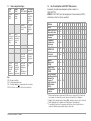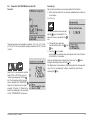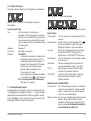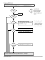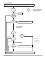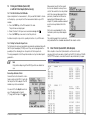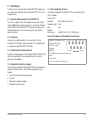
1
Operating Instructions
SECUTEST®SII
Test Instrument for DIN VDE 0701, 0702 and 0751
3-349-223-03
8/11.05
10
9
8
7
6
RS232
5
4
SONDE 5
4
Feature F01
3
L
3
2
N
2
L
VDE 0701
11
VDE T. 240
0702
T. 200
T. 1
N
VDE 0751
12
OFF
13
1
SL
1
MENU
FUNCTION-TEST
230 V
SECUTEST SII
14
15
☞
23
20
18
19
18
17
16
22
Note
Contact problems with exposed conductive parts
when using the standard probe with test tip
In order to assure good contact, surface
coatings must be removed from devices
under test with special tools at a suitable
location so that the surface has a metallic
shine.
The tip of the test probe is not suitable for
scratching away paint, because this may
impair its coating and/or mechanical
strength.
The brush probe may be more suitable than
the test probe in certain individual cases.
These operating instructions describe an
instrument with firmware version 6xx.
21
2
GOSSEN METRAWATT GMBH
Upper left figure
1 Jack for protective conductor at device under test (feature F01)
2 Jack for neutral conductor at device under test (feature F01)
3 Jack for phase conductor at device under test (feature F01)
4 Jack for connecting the probe
5 Jack for connecting the probe
6 Function selector switch
– VDE-…:
Automatic test sequence according to selected standard
– OFF:
Instrument is switched off (no disconnection from mains)
– MENU:
Setup: Device configuration
RSL… : Individual tests
– FUNCTION TEST: Function test
scroll key for menu and parameter selection
7
scroll key for menu and parameter selection
8
9 LCD panel
10 Socket connector for RS 232 interface
11 Signal lamp for mains connection error
key for entry, for starting test sequences and for finger contact
12
13 i help key (context sensitive)
14 Key next to the
symbol for switching test voltage to
the test socket (only possible if symbol LED is blinking)
15 Signal lamp for the functions text
Lower Left figure
16 Push-buttons (left and right) for releasing the handle from its snap-in position
17 Standard outlet socket (test socket) for connecting the device under test
18 Push-buttons (left and right) for releasing the lid
19 Compartment for probe and accessories
20 Lid
21 Test probe
22 Carrying handle and tilt stand
23 Cover or printer module (feature E01)
GOSSEN METRAWATT GMBH
Overview of Available Probe Types
Probe Type
Application
Special Features
Standard probe (test probe with Text current:
coil-cable and alligator clip)
200 mA
none
SK2 1)
Probe with plain cable (not coil-cable),
2 meters long
Test current:
200 mA
SK5 option
(feature KD01 or accessory)
Brush probe 1)
Can be plugged onto all above
listed probes and test probes
1)
Special probe in combination with “automatic
recognition of measuring point change”
function (see chapter 13).
Leakage current, For contacting devices under test with rotating,
protective conduc- vibrating, exposed conductive parts
tor resistance
Accessory
☞
Note
Use of probes other than those specified above:
Cables plugged into jacks 4 and 5 must be short-circuited in
order to perform the probe test, either by plugging the cable
ends together or by means of a conductive surface at the device
under test (4-wire measurement).
Remove any corrosion from the device under test.
!
Data Security
Measurement data, report data and user entries are stored to RAM at the
SECUTEST®PSI printer module (feature E01), as long as the respective
battery supplies the required amount of voltage.
Save your data to a PC on a regular basis in order to prevent any loss of
data at the printer module.
We assume no liability for data loss.
We recommend the following PC programs for data processing and data
management:
• PS3 (transmission of measurement data to a PC, documentation,
management, report generating and deadline follow-up)
• SECU 601 (program for activating the data base function in the
instrument (DBmed option), if not already available as a feature)
• PC.doc-WORD (report and list generation
• PC.doc-ACCESS (test data management)
3
Contents
Page
Contents
Page
1
Applications ...................................................................................6
9
Individual Measurements ............................................................16
1.1
1.2
1.3
1.4
Table: Types of DUTs – Tests – Regulations ....................................................6
Table: Individual Measurements and Regulations ............................................6
Table: Leakage Current Types ........................................................................7
List of Possible Options for SECUTEST®SII Device Series .................................7
2
Safety Features and Precautions ...................................................8
9.1
9.2
9.3
9.3.1
9.3.2
9.3.3
9.4
9.5
9.6
9.7
9.8
9.8.1
9.8.2
Measuring Protective Conductor Resistance ................................................. 16
Insulation Resistance RISO. .......................................................................... 17
Measuring Leakage Current ......................................................................... 19
Contact Current IContact (probe current, housing leakage current) ................... 19
Residual Current ΔI ..................................................................................... 19
Device Leakage Current IDL per DIN VDE 0751 ............................................. 19
Equivalent Leakage Current ......................................................................... 20
Probe Voltage Uprobe – Max. 300 V .............................................................. 21
Alternating / Direct Voltage UAC/DC – Max. 253 V (feature F01) ...................... 22
Resistance R (feature F01) ........................................................................... 22
Measurements with Accessories (feature F01) .............................................. 22
Alternating Current IZ with Clip-On Transformer (feature F01) ........................ 22
Temperature T with Pt100/1000 Sensor (feature F01) .................................. 23
10
Function Test ...............................................................................24
3
Initial Start-Up ................................................................................9
3.1
3.2
Connection to the Mains (230 V, 50 Hz) ..........................................................9
Automatic Recognition of Mains Connection Errors ........................................10
4
General Notes ..............................................................................10
4.1
4.1.1
4.1.2
4.2
4.3
4.4
4.5
4.6
4.7
Online Instructions .......................................................................................10
Automatic Safety Class Selection ..................................................................10
Manual or Automatic Operating Sequences ...................................................10
Online Help .................................................................................................10
Adjusting Contrast .......................................................................................11
Configuring Device Parameters, Setting Date and Time ..................................11
Configuring Measurement and Sequence Parameters ....................................11
Setting Limit Values .....................................................................................11
Saving the Settings ......................................................................................11
5
Classification of Devices Under Test ............................................12
5.1
5.2
Safety Classes ............................................................................................12
Application Parts (electrical medical devices) .................................................12
6
Abbreviations ...............................................................................13
7
Connecting the Device Under Test ...............................................14
8
Configuring Device Parameters ...................................................15
4
11
Measurements – Selector Switch Settings for Standards ...........26
11.1
11.2
11.3
11.4
11.5
11.6
11.7
Test Sequences .......................................................................................... 26
Setting Up Test Sequences .......................................................................... 27
Configuring Measuring Parameters .............................................................. 27
Testing Devices in Accordance with DIN VDE 0701, Parts 1 and 200 ............. 28
Testing Devices in Accordance with DIN VDE 0701, Part 240 ........................ 30
Testing Devices in Accordance with DIN VDE 0702:2004 .............................. 32
Testing Extension Cables for VDE 0701, Part 1, and VDE 0702
(option: EL1 adapter) ................................................................................... 34
Testing Multiple Outlets for VDE 0702 (optional EL1 adapter) ......................... 35
Testing in Accordance with DIN VDE 0751 .................................................... 36
11.8
11.9
GOSSEN METRAWATT GMBH
Contents
Page
Contents
Page
12
Storage in PSI Module (Feature E01)
and Database Operations (Feature KB01 or DBmed option) ........ 38
19
Maintenance - Calibration ........................................................... 46
12.1
12.2
12.2.1
12.2.2
Storing Measurement Data in the PSI Module ................................................38
Database Operations ...................................................................................38
Setting Up Test Sequences with PC Software ................................................38
Storing Test Results to the SECUTEST‚SII ......................................................38
20
Repair and Replacement Parts Service
DKD Calibration Laboratory and Rental Instrument Service ........ 46
21
Product Support .......................................................................... 47
13
Remote Control (Feature KD01 or SK5 Option) ............................ 38
14
Printing via PSI Module (Feature E01)
or with the Printer Adapter (DA-II accessory) ............................. 39
14.1
14.2
Print Out Test Data at the PSI Module ...........................................................39
Printing Test Results in Report Form .............................................................39
15
Direct Print-Out (feature KE01, SECU-dd option) ......................... 39
16
Characteristic Values .................................................................. 40
17
RS 232 Interface .......................................................................... 43
17.1
17.2
17.2.1
17.2.2
17.3
Transmission of Measurement Results to the SECUTEST®PSI ........................43
PC Connection ............................................................................................43
Software Evaluation of Measurement Results ................................................43
Instrument Control via Interface Commands ..................................................43
Interface Configuration and Protocol .............................................................43
18
Appendix ...................................................................................... 44
18.1
Evaluation of Measured Values for Individual Measurements
as well as for Calculated Quantities ..............................................................44
Index ..........................................................................................................45
18.2
GOSSEN METRAWATT GMBH
Condensed instructions for PS3 software for maintenance and equipment
management are provided with the PS3 CD ROM.
They include important instructions regarding the following topics:
• PS3 demo with additional instructions
• Special features for reading measured values in from a data file
5
•
•
•
1.2
Attention!
The test instrument may not be used for measurements
within electrical systems!
Table: Individual Measurements and Regulations
0.2
•
•
•
•
Insulation resistance
•
•
Equivalent leakage
current
•
•
Individual
Measurements
per Regulation
Protective conductor
resistance
DIN VDE 0751
•
Measuring and control
instruments
!
DIN VDE 0702
Laboratory instruments
DIN VDE 0751:2001
DIN VDE 0702:2004
Periodic
Testing
DIN VDE 0751:2001
DIN VDE 0701 Part 240
DIN VDE 0701 Part 1:2000
Devices under test
to be tested in
accordance with the
following regulations
DIN VDE 0751:2001
Start-up
and Modifi- Testing after
Repairs
cations
DIN VDE 0701,
part 240
Table: Types of DUTs – Tests – Regulations
DIN VDE 0701,
part 200
1.1
DIN VDE 0701,
part 1
Applications
Test current [A]
1
•
Voltage generation
devices
•
•
Electric tools
•
•
Electric heating devices
•
•
Electric motor devices
•
•
Lamps
•
•
Devices for entertainment electronics,
information and communications technology
•
•
Absence of voltage
(exposed conductive
parts)
Cable reels, extension
and connection leads
•
•
Patient leakage
current
•
•
Device leakage
current
•
Data processing and
office equipment
Electrical medical devices, application parts
6
•
•
•
•
•
Equivalent (device)
leakage current
•
•
Residual current
•
•
Contact current
•
•
•
•
Key
• Required test
GOSSEN METRAWATT GMBH
1.3
Table: Leakage Current Types
DIN VDE
0701-1
DIN VDE
0702-1
Equivalent
leakage
current
Equivalent
leakage
current
DIN VDE
The following
0751-1 (2001) is measured:
PROBE
(connected to
protective
conductor) to
L&N
Equivalent
PROBE (open
device leakage protective
current
conductor) to
L&N
Contact
current / measurement for
absence of
voltage
Probe to PE
Contact
current / measurement for
absence of
voltage
Protective conductor to PE
Device leakage current
during operation
Protective
conductor
current with
differential
current
measurement
Protective
conductor
current with
differential
current
measurement
Protective conductor interrupted, probe
to PE
Device leakSee chapter
age current
9.3.2
during operation,
differential current method
Key
NC = Normal conditions
PAT = Patient application part
PE = Potential earthing
mains protective conductor
DPE = Protective conductor of the device under test
,
1.4 List of Possible Options for SECUTEST®SII Device Series
Example for complete type designation (article number) of a
SECUTEST®SII:
M7030 E01 KD01 KE01 (only the designation of the basic device, M7030,
and features other than 00 are specified)
Features
01
A
GM
Mains Connection for
Respective Country
B
D
User Interface
Language
C
D
Configuration
(settings in the
setup menu)
D
GM
Printer Module
SECUTEST®PSI
E
w/o
Additional
Test Sockets
(cannot be retrofitted)
F
w/o
Database
DBmed Option
(Z853H)
KB w/o
with
Remote Control
SK5 Special Cable
(Z745K)
KD w/o
with
Direct Printing After
Each Measurement for
Automatic Test
KE w/o
Sequences1)
Read-Out via RS 232,
SECU-dd Option
(Z853L)
with
DKD calibration
certificate
with
1)
2)
3)
4)
GOSSEN METRAWATT GMBH
00
Design
L
w/o
02 03 04 05 06 07 08 09 10 11 99
F
CH
2)
GB
3)
with
with
4)
Each measured value is documented in this case, as opposed to the results of a
test sequence for which the poorest value for each given test is displayed.
Adapter set for international use (feature B00 - earthing contact socket - included)
With configuration for hospital beds of Safety Class 2 (pre-adjusted)
For multimeter functions, for measurements with accessories and for devices
under test without plug, including 3 plug-on quick clips
7
2
Safety Features and Precautions
The SECUTEST®SII test instrument has been manufactured and tested in
accordance with the following safety regulations:
IEC 61010-1 / DIN EN 61010-1 / VDE 0411-1 and DIN VDE 0404,
DIN VDE 0413 Part 2 and 4.
When used for its intended purpose, the safety of the user, the test
instrument and the device under test (electrical equipment or electrical
medical device) is assured.
Read the operating instructions carefully and completely before placing your test
instrument into service. Follow all instructions contained therein. Make sure that
the operating instructions are available to all users of the instrument.
Tests may only be performed by a qualified electrician or under the supervision
and direction of a qualified electrician. The user must be instructed by a qualified
electrician in the execution and evaluation of tests.
☞
Note
Manufacturers and importers of electrical medial devices must
provide documentation for the performance of maintenance by
trained personnel.
Observe the following safety precautions:
• The instrument may only be connected to electrical systems with a
maximum of 230 V which are protected with a fuse or circuit breaker
with a maximum rating of 16 A.
• Measurements within electrical systems are prohibited.
• Be prepared for the occurrence of unexpected voltages at devices
under test (for example, capacitors can be dangerously charged).
• Make certain that the measurement cables are in flawless condition,
e.g. no damage to insulation, no interruptions in cables or plugs etc.
• Grip the test probe firmly, for example during insertion into a jack
socket. Tensioning at the coil cord may otherwise cause the test probe
to snap back resulting in possible injury.
• Measuring of insulation resistance (equivalent leakage current)
The test is conducted with up to 500 V, with a current limit of
I < 10 mA. However, when touching the terminals (L or N), you will get
an electric shock which, in turn, may lead to accidents.
Feature F01: When connecting the DUT via jacks 1 to 3, special care
must be taken to avoid touching the open cables.
8
• Leakage current measurement
During leakage current measurement it is essential to ensure that the
DUT is operated at mains voltage. Exposed conductive parts may be
subject to hazardous contact voltage during the test and may not be
touched under any cricumstances. (A mains shutdown takes place
when the leakage current exceeds approx. 10 mA).
!
Attention!
The function test may only be performed after the DUT has
successfully passed the safety test!
The measuring and test instrument may not be used:
• If it demonstrates visible damage
• With damaged connector cables, measuring cables or patient ports
• If it no longer functions properly
• After extraordinary stresses due to transport
In such cases, the instrument must be removed from operation and
secured against unintentional use.
Meanings of Symbols on the Instrument
The symbols on the instrument have the following meanings:
Warning regarding dangerous electrical voltage
!
Warning concerning a point of danger
(attention: observe documentation!)
Test socket
VDE testing authority approval mark
This device may not be disposed with the trash. For further
details on the WEEE marking, please refer to our website
www.gossenmetrawatt.de and enter search key ’WEEE’.
GOSSEN METRAWATT GMBH
3
Initial Start-Up
3.1
Connection to the Mains (230 V, 50 Hz)
U L – N = 230 V
➭ Connect the mains plug at the test instrument to the mains power
outlet. The function selector switch can be set to any position.
If a mains outlet (earthing contact outlet) is not available, or if only a
3-phase outlet is available, the adapter socket can be used to connect
the phase conductor, the neutral conductor and the protective
conductor. The adapter socket has three permanently attached cables
and is included with the KS13 cable set
L1
N
green-yellow
PE
L1
!
L2
Attention!
If connection is not possible via an earthing contact outlet: Shut
down mains power first.
Then connect the cables from the coupling socket to the mains
using pick-off clips in accordance with the diagram.
Disconnection from mains power is only possible with the mains
plug.
L3
N
PE
green-yellow
L1
L2
L3
N
green-yellow
Mains Connection
GOSSEN METRAWATT GMBH
9
3.2 Automatic Recognition of Mains Connection Errors
The device automatically recognizes mains connection errors if the conditions in the following table have been fulfilled. The user is informed of the
type of error, and all measuring functions are disabled in the event of danger.
Type of Mains
Connection Error
Message
Condition
Measurements
Voltage at protective
conductor PE to finger
contact
( key)
Text appears at
LCD
Press
key
U > 40 V
disabled
Voltage at PE
> 65 V
impossible
(no supply power)
U > 25 V
disabled, although
disabling can be
deactivated1)
UL-N < 90/180 V
possible
under certain
circumstances
Protective conductor PE
and phase conductor L
reversed and/or
neutral conductor N
interrupted
Contact voltage at
protective conductor PE
to neutral conductor N
or phase conductor L
Mains voltage
too low
1)
!
lamp
lights up
Text appears at
LCD
!
lamp
lights up
In SETUP – test sequence – IT system
!
☞
10
Attention!
In either of the first two cases listed in the table above,
immediately disconnect the test instrument from the mains
and eliminate the error!
Note
Voltage at the electrical system’s protective conductor PE may
result in distorted measurement values during testing for the
absence of voltage, or during leakage voltage measurements.
4
General Notes
4.1 Online Instructions
The performance of measurements and tests is quick and easy with the
SECUTEST®SII. Integrated online instructions inform the user regarding all
required connections, necessary work steps, operator errors,
measurement results and more in all measuring modes.
Information and test results appear at the dot matrix LCD in plain text.
4.1.1 Automatic Safety Class Selection
Depending upon the type of mains plug or the connection configuration
for the device under test, the test instrument recognizes the respective
safety class and recommends its use for the measurement to be
performed.
4.1.2 Manual or Automatic Operating Sequences
Depending upon selections made in the setup menu (selector switch in
the Auto position), the next measurement is started automatically after the
current measurement has been completed, or can only be started after
manual acknowledgement. The integrated online instructions are
adequate for most tests and measurements. However, the contents of
these operating instructions should nevertheless be read and observed.
4.2 Online Help
Online help can be queried and displayed at the LCD for all measuring
and test functions, and for almost all settings. Schematic diagrams which
illustrate proper connection of devices under test to the SECUTEST®SII
can be displayed as well.
➭ Press the following key in order to query online help:
➭ Press the same key again in order to exit online help.
☞
Note
Online help can be queried during measurement by pressing
and holding the help key.
GOSSEN METRAWATT GMBH
4.3
Adjusting Contrast
MENU
Set the selector switch to MENU.
Select the Setup menu, “back” is highlighted.
Activate contrast adjustment.
Press and hold the key.
Adjust contrast.
Return to the menu.
Store the contrast setting to permanent memory with the save function in
the setup menu.
GOSSEN METRAWATT GMBH
4.4 Configuring Device Parameters, Setting Date and Time
Device parameters and functions which are valid for all selector switch
positions can be activated or deactivated with the selector switch in the
MENU position using the Setup parameter (see chapter 8 on page 15).
4.5 Configuring Measurement and Sequence Parameters
Measurement and sequence parameters, as well as functions, can be
activated or deactivated in the Setup menu (selector switch in the VDE
position) for the respective test regulation. Refer to chapter 11.3 on page
27 for the significance of the various parameters.
4.6 Setting Limit Values
Upon delivery, the limit values set forth (at the point in time of issue) in
applicable national and international standards are stored to the test instrument. Limit values for each of the respective standards can be queried
and changed if required with the Setup > Limit Values menu (selector switch
in the VDE... position), but changes can only be made which result in even
stricter testing than is required by the respective standard.
Newly entered limit values become effective immediately. However, these
are only stored to memory permanently after activating the Store function
in the Setup menu for the respective standard.
If the limit values set forth in the standards for certain safety classes need
to be restored despite individualized settings, the All Values per Standard
menu function in the Limit Values submenu must be selected and
acknowledged with the Enter key.
If the limit values set forth in the standards are changed, the instrument’s
device software can be updated via the RS 232 interface.
4.7 Saving the Settings
All of the settings and changes which have been entered to the Sequence,
Limit Values (selector switch in the VDE... position) and Zero Point (temperature measurement) (selector switch in the MENU position) menus, as well as
the selected contrast setting are retained until the selector switch is turned,
or the test instrument is disconnected from mains power. If settings and
changes should be retained even after mains power has been interrupted,
they must be saved in the Setup menu for the respective test regulation or
selector switch position (acknowledge the “Save” function).
11
5
Classification of Devices Under Test
5.1 Safety Classes
Devices assigned to all of the following safety classes are equipped with
basic insulation, and provide for protection against electrical shock by
means of various additional precautions as well.
Safety Class I Devices
Exposed, conductive parts are connected to the protective conductor so
that they are not charged with voltage if the basic insulation should fail.
Safety Class II Devices
These devices are equipped with double insulation or reinforced
insulation.
Safety Class III Devices
These devices are powered with safety extra-low voltage (SELV). Beyond
this, no voltages are generated which exceed SELV. These devices may
not be connected to the mains.
Note: The DUT may only be connected to the test instrument at jacks 1
through 3 (Feature F01). Only a visual inspection, an insulation resistance
measurement or a measurement of the supply voltage can be performed,
see parameter “SC III UV” on page 27.
Parameter Classification (in the Sequence... menu)
The SECUTEST®SII always tests in accordance with the strictest limit values of the respectively selected safety class. The test is failed if this limit
value is exceeded. However, devices under test exist for which higher limit
values are allowable.
If parameter classification is activated (= x), the user is asked if higher limit
values are allowable for the DUT. If “Yes” is entered, reevaluation ensues
and the DUT may pass the test.
The test is failed by a DUT with 300 kW with deactivated classification
function (= _), but it is passed with activated classification function (= x) if
the question is answered accordingly.
Similar possibilities for passing the test, although it might otherwise be
failed, are included in DIN VDE 0701, part 1.
If the DUT is connected via the jacks instead of the test socket, other limit
values apply because higher power consumption is possible in this case
(e.g. part 1 specifies a limit value of 1 mA per kW for equivalent leakage
current). See also table: “Maximum Allowable Limit Values for Equivalent
Leakage Current in mA” on page 20.
5.2
Application Parts (electrical medical devices)
Type B Application Parts
(body)
Devices of this type are suitable for both internal and external patient
applications, except for use in direct proximity to the heart.
These devices provide for adequate protection against shock especially
as regards:
• Reliable leakage current
• Reliable protective conductor connection if utilized
Devices of the following safety classes are allowable: I or II.
Type BF Application Parts
(body float)
Same as type B, but with type F insulated application parts.
Type CF Application Parts
(cardiac float)
Devices of this type are suitable for use directly at the heart. The
application part may not be grounded.
Devices of the following safety classes are allowable: I or II.
Examples
If the insulation resistance test is failed, or if interference suppression
capacitors have been replaced, equivalent leakage current measurement
must be performed on DUTs with heating elements in accordance with
DIN VDE 0702.
12
GOSSEN METRAWATT GMBH
6
Abbreviations
AE
B, BF, CF
OE
ΔI
ΔImax
EDLA1/A2
Error condition: application part grounded
Classifications for application parts
Operational earth
Differential current, residual current
Maximum residual current (during function test)
Equivalent device leakage current with designation A1/A2
(cross-reference in the standard)
EDLPX±PE
Equivalent device leakage current for portable x-ray
+PE: with additional PE conductor
–PE: without additional PE conductor
EDLSCII
Equivalent device leakage current for devices with
additional safety class 2 components
HE
Error condition: housing grounded
IL, I , IHL, Iprobe Leakage current (differential, probe or contact current)
IRe
Residual current
Equivalent device leakage current
IEL, IEDL
Earth leakage current (current at protective conductor)
IPE
IT system
The IT system has no direct contact between active
conductors and grounded parts: bodies within the
electrical system are grounded.
ILmax
Maximum load current (during function test)
Current at clip-on meter
IZ
L
Phase conductor
PF
Power factor
MedGV
German medical device ordinance
MPG
German medial product law
MSELV
Medical safety extra-low voltage
N
Neutral conductor
NC
Normal conditions
P
Active power
PA
Functional earth (equipotential bonding)
GOSSEN METRAWATT GMBH
R
Resistance (only with feature F01)
RISO, R-ISO
Insulation resistance
R-ISO APP-PE Insulation resistance: application part to PE
R-ISO INT. CARD. Insulation resistance: intracardiac
(application at the heart)
R-ISO NL-PE Insulation resistance: neutral/phase conductor to PE
RPE, R-PE
Protective conductor resistance
R-SL±Mains
Protective conductor resistance limit value for
+mains: DUT with mains power cable
–mains: DUT without mains power cable
(protective conductor resistance limit value for mains
power cable only = 0.1 Ω)
S
Apparent power
SELV
Safety extra-low voltage
SFC
Single-fault condition
PE
Protective conductor
UAC/DC
AC/DC voltage (only with feature F01)
Reference voltage: voltage to which all leakage voltages
UREF
make reference (as a rule nominal line voltage)
U-ISO
Test voltage for insulation measurement
UL-N
Line voltage
Voltage with which testing was executed.
UMEAS
Displayed for all leakage current measurements.
Uprobe
Probe voltage
t
On-time
Temp
Resistance temperature (only with feature F01)
W
Electrical energy
ZVEH
General Association of German Electricians
13
7
Connecting the Device Under Test
➭ Connect the DUT in accordance with the schematic diagrams included
in the online help function.
Connection of the DUT to the test instrument depends upon:
• Type of connection:
– With plug (“to test socket” parameter), applies to EL1 adapter as well
– Without plug, single or multi-phase connection
(“to jacks” parameter), only with feature F01
– No connection to tester (“permanent connection” parameter)
• Whether or not an adapter is used:
– Adapter to socket (customer specific adapter)
– AT3-med to socket, adapter for devices
which are equipped with 5-pole, 16 A CEE plugs
– AT3-III to socket, adapter for devices
which are equipped 5-pole, 32 A CEE plugs,
see AT3-III operating instructions for test sequence.
• The DUT’s safety class (I, II or III)
☞
Note
The DUT must be switched on for all tests. Switches, relays,
temperature regulators etc. must all be taken into consideration.
The test instrument automatically recognizes whether or not the DUT is
connected to jacks 1 through 3. If the instrument is equipped with feature
B00, 01 or 03, the instrument also recognizes whether or not a DUT has
been connected to the test socket. As a default setting, the program
sequence assumes that the plug from the DUT has been connected to
the test socket.
☞
14
Note
Safety Class II Devices with Safety Class I Mains Plugs
If the device under test is equipped with a safety class I plug
although it complies with safety class II, safety class I is recognized by the test instrument. If this is the case, switch from safety
class I to safety class II in the initial menu.
If the test instrument is unable to automatically recognize how the DUT
has been connected, the recommended connection setup should be
double checked and determined manually if necessary.
➭ Position the
sequence.
cursor at the second line in the start menu for the test
➭ A selection of possible connection setups can be displayed by activatkey.
ing the
➭ Select the desired connection setup with the
acknowledge with the
key.
cursor and
Omitting the Protective Conductor Test in the Case of Fully Insulated Devices
You are testing a fully insulated safety class I device (e. g. screen, submersible pump, etc.), which is not equipped with an external protective
conductor contact.
The decision as to the necessity of a protective conductor test in this case
is to be taken by a qualified electrician who should also assume responsibility.
You can omit the protective conductor test by pressing the key
as
soon as the following instruction is shown: „Please connect the probe
with the protective conductor of the DUT“.
Protective Conductor and Insulation Resistance Measurements for Permanently
Installed Devices Under Test
!
Attention!
Deactivate the electrical system which supplies power to the
device under test before connecting the test instrument!
➭ Remove the mains fuses from the device under test and disconnect
the neutral conductor N inside the device under test.
Measuring Contact Current (absence of voltage)
Make sure that the contacted parts are not grounded.
GOSSEN METRAWATT GMBH
8
Configuring Device Parameters
MENU
General device parameters can be
configured and saved using Setup with
the selector switch in the MENU position.
Select Setup/Menu and acknowledge.
Select parameter and acknowledge, change setting and acknowledge.
Settings x / – … = function activated / deactivated
Limit values ...
Illumination
Background illumination for the LCD. One of three
different conditions can be selected with the up and
down scroll keys:
x: continuously on, –: off
Numbers 1 through 9: duration in minutes after
which illumination is automatically deactivated.
Test time
Duration of a single test (0 … 255 s)
Reference voltage: Voltage to which leakage current makes reference
(as a rule nominal line voltage)
Earth fault
During the short-circuit test, testing is also performed
to determine whether or not a connection exists
between L/N and PE (short-circuit to exposed
conductive part). We assume that a short-circuit to
an exposed conductive part exists in the event of
leakage current greater than 15 mA from L/N to PE.
This value should be increased for some DUTs (in
particular high-current consumers), because greater
leakage currents are present.
GOSSEN METRAWATT GMBH
Mains wait
Line voltage is initially applied to the test socket.
However, testing does not begin until after the
number of seconds selected in “Mains wait” has
elapsed, e.g. in order to suppress measured values
during the warm-up phase.
Modem function available upon request
Modem...
Test Sequence ...
Settings x / – … = function activated / deactivated
Single-fault
If the single-fault condition has been activated, the test
is interrupted as a failure as soon as an error occurs.
Auto Class PSI
Test results (passed or failed ) for the various selector
switch positions are automatically assigned to the 8
statistics channels.
inc. Service Error
Measurement results are compensated by taking
service error into consideration (measuring error).
IT Network
Testing in IT systems can be performed by suppressing
tests for UPE-N. The UPE-N test determines whether or
not voltage is present at PE. (Leakage current measurement results may otherwise be distorted.)
Acst Sig, Seq
An acoustic signal is generated for: incorrect connection of the DUT, error in the electrical supply
system and the next test step.
Acst Sig, Meas
An acoustic signal is generated for: measured value
fluctuations and test current polarity reversal.
Auto Point
This function can be enabled with the help of an
upgrade program, e.g. Z745K (see chapter 13 on
page 38). An acoustic signal indicates whether or not
the probe is connected to the protective conductor.
The test sequence is run automatically.
Rapid signal frequency: probe connected
Slow signal frequency: next measuring point
Direct Printing
See chapter 15 on page 39.
Reports ...
Reports which have been saved to memory can be
selected from a list with an ID number and displayed
(see chapter 14.2 on page 39).
Service ...
– Time and date settings
(if a printer module is used, the same time and date
must also be entered to the PSI- menu)
– Service functions (password required)
15
9
Individual Measurements
MENU
9.1
Measuring Protective Conductor Resistance
Resistance is measured:
• Between each exposed conductive part of the housing and the
earthing contacts at the mains and the device plug (if a removable
mains connector cable is used), or the protective conductor terminal
for permanently installed devices.
• As a 4-pole measurement
• Between the earthing contacts at the mains plug and the earthing
contacts at the device plug for device connector cables
• Between the earthing contacts at the mains plug and the earthing
contacts at the coupling socket for extension cables
Connecting Safety Class I Devices to the Test Socket
When the DUT is connected, resistance is measured between the protective conductor terminal at the test socket or at the PE jack, and the probe
connection at the DUT (contact with conductive parts of the housing).
➭ In order to measure protective conductor resistance, contact a
conductive part of the housing with the probe, which is connected
to the protective conductor.
Definition
Protective conductor resistance
is the sum of the following
resistances:
• Connector cable or device
connector cable resistance
• Contact resistance at plug
and terminal connections
• Extension cable resistance if
utilized
16
During measurement, the connector cable must only be moved to the
extent it is accessible during repair, modification or testing.
If a change in resistance occurs during the manual test step of the continuity test, it must be assumed that the protective conductor is damaged,
or that one of the connector contacts is no longer in flawless condition.
Testing Extension Cables
See test sequence in chapter 11.7 on page 34.
Ω
☞
Note
“DUT connection: SC I/II” is not displayed when the test is
performed individually, but rather only during the automatic test
sequence.
GOSSEN METRAWATT GMBH
Combined Test – Differential Protective Conductor Resistance
Zero balancing is also possible for protective conductor measurement. With
zero balancing, all subsequent measurements are adjusted with an offset
such that 0 Ω is displayed for a selected reference point which is
connected to the protective conductor. When test points are contacted
with the probe which are electrically connected to this reference point, differential resistance ΔRPE between the reference point and the contacted
test point is displayed.
The mains release key
must be activated during measurement in order
to perform zero balancing. The acquired value can either be applied (the
value remains in memory until the instrument is disconnected from mains
power), permanently saved or deleted.
Maximum Allowable Limit Values for Protective Conductor Resistance
for Connector Cables with Lengths of up to 5 m
Test Standard
VDE 0701
Part 1:2000
VDE 0702:2004
VDE 0751:2001
Test Current
2)
RPE
Housing –
Device Plug
RPE
Housing –
Mains Plug
0.3 Ω 1)
> 200 mA
VDE 0751:2001
1)
OpenCircuit Voltage
+ 0.1 Ω 2)
for each
additional 7.5 m
4 V < UL < 24 V
0.2 Ω
This value may not exceed 1 Ω for permanently connected data processing
systems (DIN VDE 0701, part 240).
Total protective conductor resistance: max. 1 Ω
9.2
Insulation Resistance RISO.
Definition
Safety Class I
Insulation resistance is
measured between shortcircuited mains terminals and
the protective conductor.
Safety Classes II and III
Insulation resistance is
measured between shortcircuited mains terminals and
external conductive parts
which can be contacted with
the probe.
for SC
II
Ω
Exception for Permanently Installed Safety Class I Devices
!
Attention!
Deactivate the electrical system which supplies power to the
device under test before connecting the test instrument!
➭ Remove the mains fuses from the device under test and disconnect
the neutral conductor N inside the device under test.
➭ Connect the probe to phase conductor L at the device under test in
order to measure insulation resistance.
GOSSEN METRAWATT GMBH
17
Minimum Allowable Limit Values for Insulation Resistance
Sequence
☞
Note
All switches at the device under test must be set to the on position during measurement of insulation resistance, including temperature controlled switches and temperature regulators as well.
Measurement must be performed in all program stages for
devices equipped with program controllers.
Test Standard
Test Voltage
RISO
SC I
SC II
SC III
Heat
VDE 0701
Part 1:2000
1 MΩ
2 MΩ
0.25 MΩ
0.3 MΩ ∗
VDE 0702:
2004
1 MΩ
2 MΩ
0.25 MΩ
0.3 MΩ ∗
2 MΩ
7 MΩ
70 MΩ
70 MΩ
500 V
VDE 0751:
2001
R-ISO
* with activated heating elements
(if heating power > 3 kW and RISO < 0.3 MΩ: leakage current measurement
required)
Start measurement.
Nominal voltage is 500 V DC in this case.
Nominal voltage can be adjusted within a range of 50 V to 550 V DC.
☞
18
Notes Concerning Test Standard 0702
If the measured value is less than 0.3 MΩ for safety class I devices which
include a heating element, equivalent leakage current must be measured
as described in chapter 9.4 on page 20, and this test must be passed.
The same applies to mains powered safety class II electronic devices if
the required value of 2 MΩ is not complied with.
All exposed, conductive parts of safety class II and III devices, as well as
of battery-powered devices must be scanned with the probe and insulation resistance and/or leakage current must be measured.
Batteries must be disconnected from their terminals during testing of
battery powered devices.
Note
When insulation measurement is first started from the menu,
nominal voltage is always set to 500 V. Open-circuit voltage is
always greater than nominal voltage.
GOSSEN METRAWATT GMBH
9.3
!
Measuring Leakage Current
Attention!
During leakage current measurement it is essential to ensure
that the DUT is operated at mains voltage. Exposed conductive
parts may be subject to hazardous contact voltage during the
test and may not be touched under any cricumstances. (A
mains shutdown takes place when the leakage current exceeds
approx. 10 mA).
Select the Ixx measurement and start.
9.3.2 Residual Current ΔI
Sum of instantaneous current values which flow via the L and N conductors at the device mains connection (also known as differential current).
Residual current is practically identical to fault current in the event of an
error. Fault current: Current which is caused by an insulation defect, and
which flows via the defective point.
Attention: Residual current also includes contact current.
9.3.3 Device Leakage Current IDL per DIN VDE 0751
Device leakage current is determined by means of differential current
measurement.
Maximum Allowable Limit Values for Leakage Current in mA
+20
0
Relative Magnitude (dB):
U(f)
20 log U(f=10)
Each time line voltage is
applied to the test socket,
L and N are reversed, if
this function has been selected in the leakage current menu (see chapter
9.3 on page 19).
Frequency response is
taken into consideration in
accordance with the diagram to the right when
leakage current is
measured.
Test
Standard
IPE
VDE 0701
-1: 2000
SC I: 3.5
1 mA/kW *
IContact
NC
SFC
NC
0.5
–20
–40
VDE 0701
-240
–60
VDE 0702:
2004
ΔI
IDL
SFC
SCI: 3.5
1 mA/kW *
SC II: 0.5
0.25
SC I: 3.5
1 mA/kW *
0.5
3.5
General 0.5
10
102
103
104
105
106
Frequency (f) in Hz
VDE 0751:
2001
Notes 1 & 3 2.5
Note 2 5.0
SC II 0.1
9.3.1 Contact Current IContact (probe current, housing leakage current)
Current which flows from housing
parts which are not connected to
the protective conductor via an
L
1
external conductive connection
μΑ
N
to earth or another part of the
housing. Flow of current via the
2
protective conductor is excluded
1 Test socket (w/o protective conductor contact)
in this case.
2 Device housing
The current’s AC component is
measured. The DC component can also be measured by means of individual measurement (but not with a test sequence).
GOSSEN METRAWATT GMBH
* for devices with a heating power > 3.5 kW
Note 1:
Devices which do not have any exposed conductive parts which are
connected to the protective conductor, and which correspond with
IDL and, if applicable, IPL, e.g. data processing equipment with
shielded power pack
Note 2:
Permanently connected devices with protective conductor
Note 3:
Portable x-ray devices with mineral insulation
Key
IContact
ΔI
IDL
Housing leakage current (probe or contact current)
Residual current
Device leakage current
19
9.4
Maximum Allowable Limit Values for Equivalent Leakage Current in mA
Equivalent Leakage Current
General
Measurement of equivalent leakage current is required for:
• DIN VDE 0701 and 0702,
after passing the insulation
L
test
mA
Test Standard
IEL
VDE 0701-1:
2000
SC I: 3.5
1 mA/kW 1)
SC II: 0.5
VDE 0702:
2004
3.5
1 mA/kW 1)
SC II 0.2 2)
N
~
DUT
VDE 0751:
2001
Probe
SL
Equivalent Device Leakage Current IEDL (DIN VDE 0751)
Measurement of equivalent device leakage current is required for:
• Electrical medial devices in accordance with DIN VDE 0751, part 1
Test Setup
A high-impedance power supply
L
mA
is connected between the shortN
circuited mains terminals and all
exposed metal parts of the
DUT
housing (which are connected to
one another).
PE
~
Probe
Measurement
Current which flows over the
insulation at the device under test
is measured.
IEHL
SC I (PE or parts connected to PE)
1
Permanently connected devices with PE
10
Portable x-ray devices with additional PE
5
Portable x-ray devices without additional PE
2
Devices with mineral insulation
5
IEL Equivalent leakage current
IEHL Equivalent housing leakage current
PE Protective conductor
1)
For devices with heating power of greater than 3.5 kW
2) This limit value is not taken into consideration in the DIN VDE 0751 standard.
Connection
Refer to the schematic diagrams included with the online help for
connection instructions.
Connection Exception for Permanently Installed Safety Class I Devices
Current is measured between the probe, with which the L and N conductors must be contacted, and the protective conductor terminal PE at the
device under test for permanently installed safety class I devices under test.
!
Attention!
Disconnect mains power before connecting the test instrument!
➭ Remove the mains fuses from the device under test and disconnect
the neutral conductor N inside the device under test.
➭ Connect the probe to phase conductor L and neutral conductor N at
the device under test in order to measure equivalent leakage current.
Connection Exception for Multi-phase Devices
Equivalent leakage current measurement is not appropriate for multiphase devices.
20
GOSSEN METRAWATT GMBH
Sequence
Current, which would flow during leakage current measurement conducted in accordance with device regulations and with nominal line voltage, is displayed during this type of equivalent leakage current measurement.
Leakage current measurement in accordance with the respective device
regulations is usually not possible, because the device would have to be
set up in an electrically isolated fashion, or connected to an earth isolated
power supply to this end.
9.5 Probe Voltage Uprobe – Max. 300 V
Voltage is measured between the mains PE terminal at the test instrument
and the probe. In this case the probe can also be used as a phase finder.
Equivalent Leakage Current IEL DIN VDE 070x / 2 K
Start the Uprobe measurement.
Select the I-EL measurement and start.
Equivalent leakage current is measured between short-circuited N and L,
and the protective conductor PE.
Measuring circuit resistance is equal to 2 kΩ for VDE 0701/0702 for
simulation of mean body resistance of a human being.
Equivalent Device Leakage Current IEDL for VDE 0751 / 1 K
Select the I-EDL measurement and start.
Equivalent device leakage current is measured between short-circuited N
and L, and the probe.
Measuring circuit resistance is equal to 1 kΩ for VDE 0751 for the
simulation of mean patient resistance.
GOSSEN METRAWATT GMBH
21
9.6 Alternating / Direct Voltage UAC/DC – Max. 253 V (feature F01)
Direct, alternating and pulsating voltages of up to 253 V can be measured
between the N (2) and L (3) connector jacks.
9.8
Measurements with Accessories (feature F01)
9.8.1 Alternating Current IZ with Clip-On Transformer (feature F01)
Connection
Select the UAC/DC measurement and start.
9.7 Resistance R (feature F01)
Resistance of up to 150 kΩ can be measured between the PE (1) and N
(2) connector jacks.
Alternating current can be measured in two measuring ranges
(1 mA … 10 A ~, 1 A … 100 A~) with a clip-on current-voltage
transformer connected to the N (2) and L (3) jacks (e.g. the WZ12C).
Select the R measurement and start.
Start the IZ measurement.
Select measuring range.
22
GOSSEN METRAWATT GMBH
9.8.2 Temperature T with Pt100/1000 Sensor (feature F01)
Connection
Zero Balancing
Sensor cable resistance can be compensated with this function:
➭ Short circuit the ends of the sensor leads and determine resistance as
shown below.
Zero Balancing
The determined value can be stored
directly ( key) or changed first. The
data entry menu is opened with the
key.
Temperature can be measured within a range of –200 °C to +850 °C with
a Pt100 or Pt1000 sensor (default setting) connected to the PE (1) and N
(2) jacks.
Select the Temp measurement and start.
Select Pt100 or Pt1000 by means of
“select measuring range” with the
key. The temperature unit of measure
can be selected in the “TEMPERATURE”
setup menu. Selection can be made
amongst °C (Celsius), °F (Fahrenheit) or
Kelvin. Zero balancing is also accessible
via the “TEMPERATURE” setup menu.
GOSSEN METRAWATT GMBH
➭ Change the measured value
manually with the help of the
keys.
and
key in order to
➭ Press the
acknowledge the selected value, and to display other menu functions
at the bottom of the window.
before
Save the selected value by activating the “store value” key
exiting the balancing function with the
key.
The “delete value” command can only be accessed via the “change value”
menu. The “no zero balancing” setting is saved at the same time by
key.
activating the
23
10
Function Test
The device under test can be subjected to a
function test with line voltage via the
integrated test socket.
Function Test
In addition to testing with the selector switch in the function test position,
or with the Function parameter in the MENU position (feature F01 only), a
function test can also be performed immediately after safety testing has
been passed in accordance with the selected standard (not possible for
safety class III devices).
!
☞
☞
24
Attention!
The function test may only be performed after the DUT has
successfully passed the safety test.
Note
Each time line voltage is applied to the test socket, phase
conductor L and neutral conductor N are automatically reversed,
if the “mains polarity reversal” function has been activated (= x) in
the I leakage selector switch position.
Note
The function test is only possible if the device under test has
been connected to the test socket (21).
Measurements
The function test includes the following measurements:
– Voltage U-LN between the L and N conductors
– Residual current ΔI
(corresponds to fault current between L and N)
– Load current IL
– Active power P
– Apparent power S (calculated)
– Power factor PF (cos ϕ calculated, display > 10 W)
– Electrical energy W
– On-time t for UL–N at the socket (21)
The following values are also displayed for all selector switch positions
except MENU, after the function test has been completed:
– Maximum residual current ΔImax
– Maximum load current ILmax
– Maximum active power Pmax
Power factor is calculated from active power and apparent power. Power
factor corresponds to cos ϕ for sinusoidal quantities (line voltage and load
current).
!
Attention!
Starting the Function Test
For reasons of safety, the device under test must be switched
off before the function test is started. This precaution prevents
inadvertent start-up of a device under test which may represent
a hazard during operation, e.g. a circular saw or a disc grinder.
Ending the Function Test
After completion of the function test, devices under test must
be turned off with their own switch – especially devices with
relatively high inductivity.
GOSSEN METRAWATT GMBH
Short-Circuit Test
1 Test for shorts between conductors
N and L.
2 Test to determine whether or not
the N or L conductors are shortcircuited to the protective
conductor.
The test socket can be rendered voltage-free with the key (14), or the
function test can be ended with the
key (12).
☞
Note
A short-circuit at the device under test is recognized automatically by the test instrument. A message appears at the display
(9), and the function test is disabled.
If the
lamp blinks (15), line voltage can be switched to the test socket
with the key (14), and the measurement can be started. If the lamp (15) is
lit continuously, line voltage is present at the test socket.
GOSSEN METRAWATT GMBH
25
11
Measurements – Selector Switch Settings for Standards
If measurements need to be performed in accordance with given standards which require specific tests, and if results need to be documented
with a test report, an automatic test sequence is advisable instead of individual measurements.
➭ Connect the SECUTEST®SII to mains power.
A mains connection test is initialized (see chapter 3.2 on page 10).
➭ Connect the DUT to the test socket at the SECUTEST®SII (see chapter 7 on page 14). The test instrument initializes connection type
recognition.
to the appropriate standard.
➭ Set the selector switch
If the test instrument is equipped with features B00, 01 or 03, and if
the DUT has been connected to the test socket, safety class recognition
is performed. Otherwise, the safety class must be specified manually.
Move the cursor up into the third line in the initial window with the
key, and acknowledge with the
key. A safety class can now be
selected with the
and
keys and acknowledged with the
key.
➭ The test sequence can be configured in the Setup… menu, limit values
can be changed if necessary and database options can be selected.
➭ The test sequence is started by selecting Start test and acknowledging
key (see following chapter, “Test Sequences”.
with the
Tests which have already been included in chapters 9 through 14 are not
described here again. The only exception is measurement of extension
cables.
26
11.1 Test Sequences
Test sequences for the various standards are always run in the same
order, assuming that the device under test has been properly connected
and the mains connection test has been passed.
The test sequence can be run step by step with manual activation of each
subsequent step if this function has been specified, or automatically. Step
by step manual operation can be selected if “Manual Sequence” has been
activated under Sequence... in the setup menu in the initial window.
• Visual inspection: If “Visual Inspection” has been activated under
Sequence…
If a part is recognized as defective by the user, it must be identified as
such by selecting it with the cursor and acknowledging with the
key.
• Protective conductor measurement (for SC I devices under test only)
☞
Note
If a protective conductor connection is not possible, the mea(when the message „Connect
surement can be skipped with
probe to protective conductor“ is shown on the display).
• Evaluation of protective conductor testing
• Insulation resistance measurement
DIN VDE 0751: Only if ISO-R is activated under Sequence…
in the setup menu
DIN VDE 0702: Only if ISO-R is activated in the initial window
• Evaluation of insulation test
• Leakage current measurement
• Evaluation of each individual leakage current measurement
• Evaluation of the overall test
• Perform function test if required:
The function test can be performed each time a safety test has been
successfully completed. The blinking signal lamp indicates that the
function test should be started. Beyond this, the function test can also
be started from the Function Test selector switch position. See chapter
10 on page 24 regarding performance of the function test.
• Display test results
(the worst measured values for the test sequence)
• Save test results and print if required
GOSSEN METRAWATT GMBH
11.2 Setting Up Test Sequences
All possible sequence settings for all of the regulations are listed below.
Select the Sequence ... menu and acknowledge.
Select the Setup... menu from the initial program window and
acknowledge
Repair tests, periodic testing
Save
All of the settings in the setup menu, i.e.
configuration of measuring parameters and current
limit values, can be saved with this command. These
values remain active even after setting the selector
switch to a different position, and after disconnection
from mains power.
Sequence …
See page 27.
Limit values …
See chapter 4.6 on page 11.
Database …
Start with ID No.
x: Before each measurement is started, an entry
prompt appears requesting entry of an ID no.
An individual number can be entered (max. 20
characters) with the keypad at the PSI module
(optional), read in with a barcode scanner
(optional) or directly selected from a list.
If an incorrect entry is made:
Only complete lines can be deleted, and deletion
is only possible with the
key at the instrument.
ID no. = test sequence (feature KB01 or DBmed option)
See chapter 12 on page 38.
11.3 Configuring Measuring Parameters
Depending upon the test regulation, various measuring parameters can
be configured for the test sequence (settings: x / – = function activated /
deactivated). All possible parameters for all of the regulations are listed
below. The Sequence ... menu is accessed via the setup parameter in the
initial program window for the respective regulation.
GOSSEN METRAWATT GMBH
Select a parameter, acknowledge, change and acknowledge the change.
General Parameters
Visual inspection
Manual sequence
Auto-store
Polarity reversal
Classification
SC III UV
R-ISO LN-PE
This menu appears at the very beginning of the test
sequence.
Each test step must be acknowledged with the
key (see test sequence in chapter 8 on page 15
regarding test duration for automatic sequence)
After testing is finished, test data are automatically
stored to the SECUTEST®SII (feature KB01 or
Dbmed option), or the SECUTEST®PSI (accessory).
L an N are reversed each time line voltage is applied
to the test socket.
Questions regarding classification appear if limit
values are exceeded (see chapter 5 on page 12).
Supply voltage is measured instead of insulation
resistance for active devices under test.
Insulation resistance measurement is performed
between phase/neutral conductors and the
protective conductor.
Additional Parameters for DIN VDE 0702/0751
Auto test method
The instrument recognizes whether or not the device
under test can be switched on: Leakage or residual
current, or insulation resistance and earth leakage
current, are measured accordingly
Adapter for socket Limit values are activated for permanently connected
devices. A device under test which is normally
permanently installed can be connected to the test
socket via an adapter. No voltage may be applied to the
test socket when this test method is used.
27
11.4 Testing Devices in Accordance with DIN VDE 0701, Parts 1 and 200
The following measurements can be performed in accordance with the
above mentioned standard:
• Protective conductor measurement RPE (permanent connection or
with plug)
– Part 1/200: Test current: ±200 mA DC
• Insulation resistance measurement RISO
Part 1
The following safety class I through III appliances and electrical equipment
can be tested in this selector switch position, for example:
• Devices with electric motors
• Electrical heating devices
• Electrical tools
• Light fixtures
SC I extension cables can also be tested (see chapter 11.7 on page 34).
Part 200
Mains powered, safety class I through III electronic devices, e.g.
consumer electronics, can be tested in this selector switch position:
• Stereo equipment, televisions
The following maximum values for equivalent leakage current apply for
mains powered electronic devices per DIN VDE 0701, part 200:
– Devices with single-phase power supply:1 mA
– Devices with multi-phase power supply: 0.5 mA
Check connection parameters and start test.
To Socket
Class
Ext. Cable
ID No.
Setup …
☞
28
This is the default setting. Refer to chapter 7 on page
14 for other types of connection.
If the test instrument is equipped with features B00,
01 or 03, and if the DUT has been connected to the
test socket, safety class recognition is performed
(SC I or SC II). Otherwise, the safety class must be
specified manually.
x: Extension cables or connector cables which are
longer than 5 m can be tested with the help of the
EL1 adapter (optional), either separately or in
combination with a device.
See parameters database in chapter 11.2 on page
27.
See chapter 11.2 on page 27 regarding setup of the
measuring sequence.
Note
Extension cables can only be tested in the VDE 0701 part 1 and
VDE 0702 selector switch positions if the EL1 accessory
adapter is used (see chapter 11.7 on page 34).
GOSSEN METRAWATT GMBH
Test Sequence per VDE 0701
Select connection, select test regulation VDE 0701 part 1 or 200, classify the DUT (SC I, II or III), part 1: extension cable X/– (with/without)
Visual inspection
OK?
Yes/No
Yes
Test
OK?
Framed with dashed line:
The test is only run if it has been activated in
the initial program window, or in the Setup
menu under Sequence ...
Switch DUT on
Short-circuit
at DUT?
No
No
Safety Class I only: Contact all exposed, conductive parts with the
probe. The test can be repeated as often as desired for various
protective conductor parts with the manual sequence*
SC I: RPE
OK?
Yes
Yes
or
No
IL
OK?
RISO+IEL
OK?
* If it is not clear whether or not all
exposed, conductive parts are
connected to one another or to the
protective conductor, testing can be
performed in the manual mode.
No
Yes
No
Test
OK?
Yes
No
Start
function test
Switch line voltage to test socket, start function test
Display results, save/print report
GOSSEN METRAWATT GMBH
29
11.5 Testing Devices in Accordance with DIN VDE 0701, Part 240
Testing safety class I and II data processing equipment and office machines as
individual devices and in combination with one another.
The following measurements can be performed in accordance with the
above mentioned standard:
• Protective conductor RPE (permanent connection or with plug)
Test current: DC ±200 mA
• Housing leakage current I
• According to DIN VDE 0701, part 240, the device protective conductor must be tested after maintenance, repair or modification of data
processing equipment and office machines, and exposed, conductive
parts must be tested for the absence of voltage. This applies to:
• Safety class I devices for all exposed, conductive parts which are
accessible to the user, and which are not connected to the protective
conductor
• Safety class II devices (totally insulated devices) for all exposed,
conductive parts which are accessible to the user
with the mains plug poled in both directions
Setting Up the Test Sequence
See chapter 11.4 regarding the test sequence.
Special Parameters
Combined Testing
Safety class I and II devices can be tested individually or in
combination. All protective conductor connections are tested
first for interconnected safety class I devices, and then – as is
also the case for interconnected safety class II devices – all
exposed, conductive parts.
Connecting the Device Under Test
➭ Connect the test instrument and the DUT as described below:
– Connect both devices to separate mains outlets.
The outlets to which the test instrument and the safety class I DUT
are connected must share a common protective conductor!
– Or connect the test instrument to the mains and the DUT to the
test socket at the test instrument.
30
Data Processing / Office Machines
Permanently connected or with plug
To test socket at the instrument
The requirement for testing with the mains
plug poled in both directions can be fulfilled
by connecting the DUT to the test
socket at the instrument, and by
activating mains polarity reversal under
“Sequence” in the setup menu. Each
time the key (14) is activated, phase
conductor L and neutral conductor N
are reversed at the test socket.
!
Attention!
Testing with mains polarity reversal or with the mains plug poled
in both directions results in interruption of supply power to the
affected data processing equipment or office machine. This test
may thus only be conducted with the consent of the operator of
the data processing equipment or office machine.
If the DUT is defective, the electrical system’s RCCB may be
tripped during testing which would also result in interruption of
supply power to the affected equipment or office machine.
The manufacturer of the test instrument assumes no liability for
loss of data or other damage which results from use of the test
instrument.
GOSSEN METRAWATT GMBH
Test Sequence per VDE 0701, Part 240
Select connection, select test regulation VDE 0701, part 240, classify the DUT (SC I, II or III), combination testing X/– (yes/no)
Visual inspection
OK?
Yes/No
Yes
Test
OK?
Switch DUT on
Framed with dashed line:
The test is only run if it has been
activated in the initial program
window, or in the Setup menu under
Sequence ...
Short-circuit
at DUT?
No
No
SC I: RPE
OK?
Contact all exposed, conductive parts with the probe.
The test can be repeated as often as desired for various protective
conductor parts with the manual sequence*.
Yes
No
IL
OK?
* If it is not clear whether or not all
exposed, conductive parts are
connected to one another or to the
protective conductor, testing can
be performed in the manual mode.
Switch line voltage to test socket, start measurement
Reverse mains polarity, perform measurement again
Yes
No
Start
function test
Switch line voltage to test socket, start function test
Display results (for combination testing: additional display of differential resistance), save/print report
GOSSEN METRAWATT GMBH
31
11.6 Testing Devices in Accordance with DIN VDE 0702:2004
The following measurements can be performed in accordance with the
above mentioned standard:
• Protective conductor RPE (permanent connection or with plug)
Test current: DC ±200 mA
• Insulation measurement RISO (can be deactivated,
e.g. if danger exists that voltage sensitive components in data
processing systems might be damaged) plus equivalent leakage
current
or
• Contact current for safety class II
or
• Differential current
Check connection parameters and start test.
To Socket
Class
Ext. Cable
ISO-R
ID No.
Setup …
32
This is the default setting. Refer to chapter 7 on page
14 for other types of connection.
If the test instrument is equipped with features B00,
01 or 03, and if the DUT has been connected to the
test socket, safety class recognition is performed
(SC I or SC II). Otherwise, the safety class must be
specified manually.
x: Extension cables or connector cables which are
longer than 5 m can be tested with the help of the
EL1 adapter (optional), either separately or in
combination with a device.
x: Insulation resistance measurement is performed.
See parameters database in chapter 11.2 on page
27.
See chapter 11.2 on page 27 regarding setup of the
measuring sequence.
GOSSEN METRAWATT GMBH
Test Sequence per VDE 0702:2004
Select connection, select test regulation VDE 0702, classify DUT (SC I, II or III), extension cable X/– (with/without)
Visual inspection
OK?
Yes/No
Yes
Test
OK?
Framed with dashed line:
The test is only run if it has been activated in the initial program window, or in
the Setup menu under Sequence ...
Switch DUT on
Short-circuit
at DUT?
No
No
SC I: RPE
OK?
Contact all exposed, conductive parts with the probe
Yes
If there are reservations against
an insulation measurement
RISO
OK?
Yes/No
RISO and IL OK?
No
IL*
OK?
IL*
OK?
No
Yes
RISO and IL OK: Yes
No
Start
function test
* Residual current,
contact current (direct)
or equivalent leakage current
Switch line voltage to test socket, start function test
Display results, save/print report
GOSSEN METRAWATT GMBH
33
11.7 Testing Extension Cables for VDE 0701, Part 1, and VDE 0702
(option: EL1 adapter)
Extension Cables up to 5 m Long
Protective conductor resistance between the earthing contact at the
mains plug and all exposed metal parts may not exceed 0.3 Ω for safety
class I devices. This value may not exceed 1 Ω for permanently
connected data processing systems (DIN VDE 0701, part 240).
Extension and Connector Cables Longer than 5 m
Per DIN VDE 0702, an additional cable resistance of 0.1 Ω, however, not
more than 1 Ω, is allowable as of a length of 5 m for each additional
7.5 m.
Resistance testing for cables longer than 5 m is thus advisable (see also
limit values on page 17).
☞
Performing the Test
➭ Connect the extension cable to the EL1 adapter as shown in the figure
above.
➭ Select the “Ext. Cable” test from the initial menu with the cursor and
acknowledge with the
key: Ext. Cable x WITH EL1.
➭ Select “Start Test” with the
key.
➭ Start the measurement sequence with the
key.
➭ First perform and acknowledge visual inspection of the extension cable.
➭ Enter the length of the cable with the
the
key.
and
keys. Acknowledge with
Note
The EL1 accessory adapter is required for testing for shortcircuiting and interruption of single-phase extension cables.
Connecting the Extension Cable or the Multiple Outlet
PROBE
5
Device Under Test =
Extension Cable
4
(21)
SECUTEST
EL1
☞
34
Note
The keys in the adapter’s handle have no function.
GOSSEN METRAWATT GMBH
11.8 Testing Multiple Outlets for VDE 0702 (optional EL1 adapter)
➭ up to version 5.10:
Do not select “WITH EL1” in the initial menu. The following must
appear in the line: Ext. Cable – WITH EL1. “Manual sequence” must be
selected.
➭ from version 5.11 onwards:
Select “X WITH EL1” in the initial menu. The following must
appear in the line: Ext. Cable X WITH EL1. “Manual sequence” must be
selected.
➭ A visual inspection must always be performed. It may thus be
necessary to unreel the cable from its drum or reel.
➭ Protective conductor resistance measurement: Contact the first outlet
with the EL1 adapter. Each time you are ready to contact the next
outlet, press the
key to repeat the test.
➭ After measurement has been completed for all outlets, reinsert the test
probe in order to continue with the performance of subsequent tests
as described in chapter 11.6.
GOSSEN METRAWATT GMBH
35
11.9 Testing in Accordance with DIN VDE 0751
The following measurements can be performed in accordance with the
above mentioned standard:
• Protective conductor measurement RPE, test current: 200 mA DC
• Insulation measurement RISO (can be additionally activated)
– R-ISO LN-PE
(Insulation resistance LN to protective conductor)
• Equivalent device leakage current IEDL
• Device leakage current (direct measurement or by means of differential
current)
• Patient leakage current with probe
Check connection parameters and start test.
(Patient leakage current is not possible with SFC „Mains at Application Part“)
• Equivalent patient leakage current with probe
Leakage current is converted to reference voltage (see limit values,
chapter 8 on page 15).
Reference voltage must be matched to the supply voltage range.
36
To
Socket
This is the default setting. Refer to chapter 7 on page 14 for
other types of connection.
Class
If the test instrument is equipped with features B00, 01 or 03,
and if the DUT has been connected to the test socket, safety
class recognition is performed (SC I or SC II).
In all other cases, or if it is not clear whether or not all
exposed, conductive parts are connected to one another or
to the protective conductor, the safety class can be selected
manually.
Type
Select the type of device under test from a list (device type).
If “Old devices” is selected, limit values specified in
DIN VDE 0702 are used.
Ap. parts... (BF): The type of application parts can be changed manually:
Select the “Ap. Parts” line with the
or
key, acknowledge
with the
key and change with the
or
key.
ID No.
See parameters database in chapter 11.2 on page 27.
Setup … Refer to chapter 11.2 on page 27 regarding setup of the
measuring sequence.
GOSSEN METRAWATT GMBH
Test Sequence per VDE 0751
Select connection, select test regulation VDE 0751, classify the DUT (SC I or II), application part? (type B/BF/CF)
Test
OK?
Visual inspection
OK?
Yes/No
Yes
Switch DUT on
Framed with dashed line:
The test is only run
– If it has been activated in the initial
program window, or in the Setup
menu under Sequence ...
or
– If at all possible
Short-circuit
at DUT?
No
No
SC I: RPE
OK?
Yes
No
RISO
OK?
Yes
No
IEDL
ΔI OK?
IDL
Yes
No
IEPL
IPL OK?
Contact all exposed, conductive parts with the probe.
The test can be repeated as often as desired for various protective
conductor parts with the manual sequence*.
* If it is not clear whether or not all
exposed, conductive parts are
connected to one another or to the
protective conductor, testing can be
performed in the manual mode.
Contact all exposed, conductive parts with the probe.
ΔI or IDL: only if the device is switched electronically
Application parts B, BF, CF
Yes
No
Start
function test
Switch line voltage to test socket, start function test
Display results, save/print report
GOSSEN METRAWATT GMBH
37
12
Storage in PSI Module (Feature E01)
and Database Operations (Feature KB01 or DBmed option)
12.1 Storing Measurement Data in the PSI Module
Upon completion of a measurement – „Test passed/Test failed“ is shown
on the display – you can save the measurement data to the memory of
the PSI module.
➭ Press the STORE key at the PSI module to this end.
A text entry field is shown.
➭ You may now enter your comments on the measurement and/or an
identification number.
➭ Press the STORE key once more to save the measurement data and
your comments.
The message: „Data are stored“ is displayed.
A detailed description is given in the operating instructions of your PSI
module under chapter „How to display, print and store protcol“.
12.2 Database Operations
12.2.1 Setting Up Test Sequences with PC Software
This function must be activated with the help of upgrade software, e.g.
the Z853H program.
Up to 99 test sequences can be uploaded for each of the selector switch
positions from a PC via the serial port at the SECUTEST®SII test instrument. After testing has been performed, the test results are saved to the
same database, if a PSI module has not been connected. The maximum
possible sum of test sequences and test results is 127.
Test results are stored to the PSI module if one has been connected.
The database can be used in different ways:
(see also chapter 11.2 on page 27)
1. Stored test results can be displayed
(select the ID no. and then activate the “from database” function).
The desired test sequence can be selected with the scroll keys.
2. If “ID no. = test sequence” has been activated (X), the first two
characters of the ID number determine the test sequence.
38
Example:
ID number = 037890sk3r
Test sequence number 03 is executed.
Test sequence 03 is the test sequence which appears at the
third position from the top of the list.
If this number does not exist, the default sequence is executed.
3. Executed test sequences are stored to memory at the instrument as
test results. The test results can also be displayed at a later point in
time with the “test sequence settings” submenu in the “general setup”
menu.
☞
Note
The database can only be generated or deleted with the help of
a PC with a terminal program, or appropriate application
software.
12.2.2 Storing Test Results to the SECUTEST®SII
This function must be activated with the help of upgrade software, e.g.
the Z853H program.
If no PSI module has been connected, up to 99 reports can be stored to
the test instrument. The reports can be viewed as required at the instrument and can be printed out, for example with the help of DA-II software
or a terminal program.
The reports are sorted by time and date and are displayed with the ID
number. If no ID number was assigned, date and time are automatically
saved instead.
13
Remote Control (Feature KD01 or SK5 Option)
This function must be activated with the help of upgrade software, e.g.
the Z745K program.
The protective conductor measurement is expanded to include the
function: “automatic recognition of measuring point change”.
During protective conductor measurement, the instrument recognizes
whether or not the probe is in contact with the protective conductor, and
indicates these two possible conditions by means of different acoustic
signals.
This function is helpful if several protective conductor connections need to
be tested. The function can be activated with the “auto measuring point”
function in the “test sequence setup” menu (see “changes to the switch
position menu” above).
GOSSEN METRAWATT GMBH
14
Printing via PSI Module (Feature E01)
or with the Printer Adapter (DA-II accessory)
14.1 Print Out Test Data at the PSI Module
Upon completion of a measurement – „Test passed/Test failed“ is shown
on the display – you can print out the measurement data via your PSI
module.
➭ Press the PRINT key at the PSI module to this end.
The print menue is displayed.
➭ Select „Protocol“ with your cursor and acknowledge with
.
➭ Press the PRINT key once more to start the print-out.
A detailed description is given in the operating instructions of your PSI module.
14.2 Printing Test Results in Report Form
Test instruments can be connected to commercially available printers with
the DA-II printer adapter (Z745M), even if they are not equipped with a
parallel port, thus allowing for on-site print-out of test reports etc.
The only prerequisite is that the printer module is set up for direct report
generation.
☞
Measurement results for the current
test can be stored to memory, the results of the current test can be printed
out to the corresponding report form,
previously stored test results can be
queried (scroll: DBmed option, see
chapter 12) and all saved measurement
results can be printed out from this
menu.
Print-out is executed directly to the
Centronics printer via printer adapter
DA-II.
The matching report form is automatically selected for the standard selected with the selector switch.
15
Direct Print-Out (feature KE01, SECU-dd option)
After completion of each test (individual test or at the end of a test
sequence), test results are read out directly via the RS 232 interface. If the SECUTEST®PSI has been connected, the results are printed directly to paper.
Note
Only printers disposing of the ASCII type font are suitable for
use.
Connecting a Centronics Printer
Connect the test instrument to a Centronics printer via the RS 232 port with
the help of the DA-II adapter. The PSI
module may not be connected.
You can shift to the Report menu from
any of the displayed test results
(1st page) with the help of the
key.
GOSSEN METRAWATT GMBH
39
16
Characteristic Values
Measuring
Measuring Range / Resolu- Nominal Open-Cir- Nominal Short- Internal Reference
cuit Volt- Current Circuit
ResisResist.
Error
Nominal Range of
tion
Voltage
RREF
age U0
IN
Cur. IK tance RI
Use
UN
0.000 … 2.100 Ω
1 mΩ
4.5 … 9 V
>200 mA
±(5% rdg. + 10 d)
Device Protective
—
—
—
—
DC
DC
> 10 d
Conductor
2.11 … 31.00 Ω
10 mΩ
Resistance RPE
0.050 … 1.500 MΩ 1 kΩ
±(5% rdg. +10 d)
50 … 500 1.0 • UN …
> 1mA < 10 mA
—
—
Insulation Resistance 1.01 … 10.00 MΩ 10 kΩ
1.5 • UN
V DC
RISO
10.1 … 310.0 MΩ 100 kΩ
±(10% rdg. +10 d)
0.00 … 21.00 mA
10 μA
230 V~
Equivalent Leakage
—
– 20/
—
< 3.5 mA > 72 kΩ 1/2 kΩ 5 ±(5% rdg. +10 d)
20.1 … 120.0 mA 100 μA
Current IEL or. IDL
+10 %
0.0 ... 310.0 μA
100 nA
Equivalent Patient
230 V~
1 kΩ
1 μA
—
– 20/
—
< 3.5 mA > 72 kΩ
±(5% rdg. +10 d)
Leakage Current IEPL 0.300 ... 2.100 mA
±10 Ω
+10 %
2.00 ... 11.00 mA
10 μA
Function Test
Tests per DIN VDE 0701 / 0702 / 0751
Func- Measured Quantity
tion
2)
3)
40
0 … 310 μA 6
0.300 … 3.500 mA
0.1 μA
1 μA
0.0 ... 310.0 μA
0.300 ... 3.100 mA
100 nA
1 μA
3.10 ... > 15.00 mA
10 μA
0.000 … 3.100 mA~
3.00 … 31.00 mA~2
1 μA
10 μA
Line Voltage UL–N
Load Current IV
207.0 ... 253.0 V~
0 ... 16.00 A RMS
0.1 V
10 mA
Active Power P
0 ... 3700 W 3
1W
Apparent Power S
Power Factor LF,
sinusoidal: cos ϕ
Differential Current
ΔI between L and N
per DIN VDE 0702
±(2.5% rdg. + 5d)
> 10 d
±(2.5% rdg. +5 d)
> 10 d
±(10% rdg. +10d)
Overload Capacity
Value Duration
253 V
cont.
253 V
cont.
±(2.5 % rdg. +5 d)
> 10 d
253 V
cont.
±(2.5% rdg. +5 d)
> 10 d
253 V
cont.
cont.
—
—
—
—
1/2 kΩ 5
—
±(5% rdg. +10 d)
±(2.5% rdg. +5 d)
> 10 d
253 V
—
—
—
—
1 kΩ
—
±(5% rdg. +10 d)
±(2.5% rdg. +5 d)
> 10 d
253 V
—
—
—
—
—
—
±(10% rdg. +10 d)
> 10 d
±(5% rdg. +5 d)
> 10 d
2
2
—
—
—
—
—
—
—
—
—
—
—
—
253 V
20 A
253 V
20 A
cont.
10 min.
cont.
10 min.
2
2
253 V
cont.
0 ... 4000 VA
1 VA
Calculated value UL–N • IV
0.00 ... 1.00
0.01
Calculated value P / S, display > 10 W
0.00 ... 31.00 mA~
10 μA
—
0 ... 253.0 V
0.1 V
—
, and
The device leakage current step of the test sequence is executed by means of
differential current measurement for testing per DIN VDE 0751.
As of 25 mA: shutdown by residual current measurement within 100 ms
Measured value P and calculated value S are compared and the smaller of the two is displayed.
UProbe
1)
Contact Current or
Housing Leakage
Current IProbe or IDL
Patient Leakage
Current IPL
AC/DC Components Measured
Separately
Differential
Current ΔI
between L and N 1
Intrinsic Error
—
Probe voltage
—
4)
5)
6)
—
±(2.5% rdg. +5 d)
±(2.5% rdg. +5 d)
±(5% rdg. +10 d)
> 20 d
±(5% rdg. +10 d)
cont.
24
> 20 s
±(10% rdg. +5 d)
±(10% rdg. +10 d)
> 10 d
±(5% rdg. +5 d)
—
±(2.5% rdg. +5 d)
> 10 d
Measuring circuit becomes highly resistive, indication at display
For DIN VDE 0701/0702: 2 kΩ, for DIN VDE 0751: 1 kΩ
This measuring range with DIN VDE 0751 only
GOSSEN METRAWATT GMBH
Multimeter Measurements for Devices with Feature F01
Function
UAC/DC
Measured Quantity Measuring Range /
Nominal Range of
Use
Resolution
OpenCircuit
Voltage
U0
0 ... 253.0 V
, and
0.1 V
—
—
0 ... 150.0 kΩ
Voltage
Low Voltage, SC III
R
Resistance
IClip
Current with
Clip-On CurrentVoltage Transformer
WZ12C
Temp.
Temperature
with Pt100/Pt1000
Sensor
Reference Ranges
Line Voltage
Line Frequency
Waveshape
Ambient Temperature
Relative Humidity
Load Resistance
Nominal Ranges of Use
Line Voltage
Line Frequency
Line Voltage
Waveshape
Temperature
Ambient Conditions
Storage Temperature
Operating Temperature
Accuracy Range
Relative Humidity
Elevation
Deployment
ShortCircuit
Current
IK
Internal
Resistance
RI
Measuring
Error
Intrinsic Error
—
±(2.5 % rdg. +5 d)
—
±(5% rdg. +10 d)
> 10 d
Overload Capacity
Value
Duration
253 V
cont.
100 Ω
< 20 V –
1.1 mA
—
—
±(1% rdg. +3 d)
253 V
cont.
0.000 ... 10.00 A
1 mA
—
—
1.5 MΩ
—
±(3% rdg. +10 d)
253 V
cont.
0 ... 100 A
1A
—
—
1.5 MΩ
—
> 10 d
without clip-on device
253 V
cont.
cont.
1.1 mA
—
—
±(2% rdg. +1 °C)
±(1% rdg. +1 °C)
±(2% rdg. +1 °C)
10 V
< 20 V –
10 V
cont.
10 V
cont.
– 200 ... – 50 °C
1 °C
– 50.1 ... + 300.0 °C 0.1 °C
+300 ... +850 °C
1 °C
230 V ±0.2%
50 Hz ±0.1%
Sine (deviation between effective and rectified
value < 0.5%)
+23 °C ±2 K
40 … 60%
Linear
207 V … 253 V
50 Hz
Sine
0 °C … + 50 °C
– 20 °C ... + 60 °C
– 10 °C ... + 50 °C
0 °C ... + 50 °C
Max. 75%, no condensation allowed
Max. 2000 m
Indoors, except within specified ambient
conditions
GOSSEN METRAWATT GMBH
Influencing Quantities and Influence Error
Influencing Quantity /
Sphere of Influence
Designation
Influence Error
per
± … % of Measured Value
DIN VDE 0404
Position Change
E1
Change in Test Setup Supply Power
E2
2.5
Specified influence error applies per
10 K change in temperature:
Temperature Fluctuation
0 … 21 °C and 25 … 40 °C
—
E3
1 in case of PE measurement
0.5 for all other measuring ranges
Current at Device Under Test
E4
2.5
Low-Frequency Magnetic Fields
E5
2.5
Impedance at Device Under Test
E6
2.5
Capacitance, Insulation Measurement
E7
2.5
E8
2 for capacitive load (for equivalent
leakage current)
Waveshape of Measured Current
49 … 51 Hz
45 … 100 Hz
1 (for contact current)
2.5 for all other measuring ranges
41
Power Supply
Line Voltage
Line Frequency
Power Consumption
for function test
Electrical Safety
Safety Class
Nominal Voltage
Test Voltage
Measuring Category
Fouling Factor
Safety Shutdown
207 V … 253 V
50/60 Hz
Approx. 30 VA
Continuous max. 3600 VA,
power is conducted through the instrument only,
switching capacity ≤ 16 A
I per IEC 61010-1/EN 61010-1/VDE 0411-1
230 V
3.7 kV 50 Hz
II
2
Where differential current at the
DUT > 25 mA
Shutdown time: < 100 ms
Probe current: > 10 mA, < 1 ms
Electromagnetic Compatibility
Generic Standard
DIN EN 61326:2002
Interference Emission
Multiple dot matrix display, 128 x 128 pixels
LxWxH: 292 mm x 138 mm x 243 mm
Standard instrument: approx. 4.0 kg
Housing:
IP 40
Terminals:
IP 20 per
DIN VDE 0470 part 1 / EN 60529
Extract from table on the significance of IP codes
IP XY
(1st digit X)
0
1
Protection against
foreign object entry
not protected
≥ 50.0 mm dia.
2
≥ 12.5 mm dia.
2
3
4
≥ 2.5 mm dia.
≥ 1.0 mm dia.
3
4
RS 232 Interface
Type
Configuration
Connection
IP XY
(2nd digit Y)
0
1
Protection against the
penetration of water
not protected
vertically falling drops
vertically falling drops with
enclosure tilted 15°
spraying water
splashing water
RS 232C, serial, per DIN 19241
9600, N, 8, 1
9-pin subminiature socket connector
Class
EN 55022
B
Interference Immunity
Test value
EN 61000-4-2
Contact/atmos. - 4 kV/8 kV A
EN 61000-4-3
10 V/m
C
EN 61000-4-4
Mains connection - 2 kV
B
EN 61000-4-5
Mains connection - 1 kV
A
EN 61000-4-6
Mains connection - 3 V
A
EN 61000-4-11
0.5 period / 100%
A
42
Mechanical Design
Display
Dimensions
Weight
Protection
Feature
GOSSEN METRAWATT GMBH
17
RS 232 Interface
The RS 232 port is used to connect the SECUTEST®PSI module (accessory), which can be installed to the lid of the SECUTEST®SII, to a PC or a
barcode scanner.
17.1 Transmission of Measurement Results to the SECUTEST®PSI
Test results – except for results from individual measurements (selector
switch in MENU position) and the function test – can be transmitted from
the SECUTEST®SII to the SECUTEST®PSI module, where they can be
stored and printed out in the form of measuring, test and statistical
reports at any time.
17.2 PC Connection
Connection to an IBM compatible PC is also possible. The PC is
connected to the interface at the test instrument, or to the interface port
at a previously installed SECUTEST®PSI module.
17.2.1 Software Evaluation of Measurement Results
Convenient software programs such as PC.doc-WORD, ACCESS or PS3
allow for easy generation of measuring and test reports, as well as
archiving of measured data.
17.3 Interface Configuration and Protocol
The interface included with the SECUTEST®SII is in compliance with the
RS 232 standard.
Technical Data:
Baud Rate
9600 baud, permanently set
Character Length 8 bits
Parity
none
Stop Bits
1
Data Protocol
per DIN 19244, X_ON / X_OFF protocol
Connector Pin Assignments for 9-Pin Subminiature Socket Connector:
1: External in + (for internal use only)
1
2: TXD (transmitter output)
3: RXD (receiver input)
4: External in +
6
5: GROUND
6: +5 V (500 mA output, for barcode scanner only)
7: Ext. in –
8: Control output
9: +9 V (1.5 A output, for PSI module only)
3
2
7
4
8
5
9
17.2.2 Instrument Control via Interface Commands
All key functions included with the SECUTEST®SII can be simulated with
the help of interface protocols, and the following parameters can be
queried:
• Type of measurement and measuring range
• Test setup
• Measurement sequence progress
• Detailed measurement results
GOSSEN METRAWATT GMBH
43
18
Appendix
18.1 Evaluation of Measured Values for Individual Measurements
as well as for Calculated Quantities
In order to assure that the limit values for the individual measurements
are always observed, device measuring error must be taken into
consideration.
The table in the appendix allows for calculation of the required minimum
display value for each respective measurement which must appear at the
instrument in consideration of measuring error (under nominal conditions
of use), in order to assure that the required limit value is not fallen short of
(DIN VDE 0413, part 1). Intermediate values can be interpolated.
Tables for the calculation of minimum display values for insulation
resistance and maximum display values for protective conductor
resistance, equivalent leakage current, probe current and residual
current in consideration of device measuring error:
RISO MΩ
Limit Value
0.100
0.250
0.500
1.000
2.000
5.000
7.000
10.00
20.00
75.00
Measuring Error for Test Sequences
The test instrument takes respective measuring error into consideration
during automatic test sequences, and corrected results are entered into
the test report, as long as this function has been activated in the setup
switch position under “include service error”.
1)
Maximum
Display Value
0.085
0.180
0.275
0.370
0.465
0.560
0.655
0.750
0.845
0.940
1.035
Limit Value
0.100
0.200
0.300
0.400
0.500
0.600
0.700
0.800
0.900
1.000
1.100
Depending upon resolution
IEL mA
Maximum
Display Value
1.00
0.85
3.50
3.23
7.00
6.55
10.00
9.40
15.00
14.15
20.00
18.90
Limit Value
44
RPE Ω
Minimum
Display Value
0.115
0.273
0.535
1.060
2.200
5.350
7.450
10.60 or 12.5 1
23.00
83.50
Iprobe mA
Maximum
Display Value
0.085
0.227
0.465
0.940
1.890
3.315
IRI mA
Limit Value
Limit Value
0.100
0.250
0.500
1.000
2.000
3.500
0.25
0.50
1.00
2.00
3.50
5.00
7.00
10.00
15.00
20.00
25.00
Maximum
Display Value
0.12
0.35
0.80
1.70
3.05
4.40
6.20
8.90
13.40
17.90
22.40
GOSSEN METRAWATT GMBH
18.2 Index
I
S
A
Illumination ..............................................................15
Incl. Service Error ....................................................15
Individual Measurements ..........................................16
Insulation Resistance ...........................................6, 17
Insulation Resistance Limit Values ............................18
Interface ..................................................................43
IT Network ...............................................................15
Safety Class I Devices .............................................. 12
Safety Class II Devices ............................................. 12
Safety Class III Devices ............................................ 12
Saving Settings to Memory ...................................... 11
SC I I I UV ............................................................... 27
Service ................................................................... 15
Setting Date and Time ............................................. 15
Setting Limit Values ................................................. 11
Short-Circuit Test .................................................... 25
Single Fault ............................................................. 15
SK5 Option ............................................................. 38
Absence of Voltage ................................................ 6, 7
Acoustic Signal, Measurement ................................. 15
Acoustic Signal, Sequence ....................................... 15
Adapter for Socket ................................................... 27
Alternating / Direct Voltage UAC/DC ......................... 22
Auto Class PSI ........................................................ 15
Auto Point ............................................................... 15
Auto Test Method .................................................... 27
Auto-Store .............................................................. 27
C
L
Limit Values ............................................................15
M
Classification ..................................................... 12, 27
Configuring Device Parameters .......................... 11, 15
Configuring Measurement Parameters ...................... 11
Connecting the Device Under Test ............................ 14
Contact Current ......................................... 6, 7, 14, 19
Contrast Adjustment ................................................ 11
Mains Connection Errors ..........................................10
Mains Power Outlet ....................................................9
Mains Wait ..............................................................15
Manual Sequence ....................................................27
Measurements with Accessories ...............................22
Measuring Error .......................................................44
Modem ...................................................................15
D
O
DBmed Option ......................................................... 38
Device Leakage Current ................................... 6, 7, 19
Differential Current Method ........................................ 7
Direct Printing ......................................................... 15
Online Help .............................................................10
E
Earth Fault .............................................................. 15
Equivalent Device Leakage Current ............. 6, 7, 20, 21
Equivalent Leakage Current .............................. 6, 7, 21
Extension Cables ..................................................... 34
F
Features ................................................................... 7
Finger Contact ........................................................ 10
First Measured Values ............................................. 28
Frequency Response ............................................... 19
Function Test .......................................................... 24
GOSSEN METRAWATT GMBH
P
Patient Leakage Current .............................................6
Periodic Testing .........................................................6
Polarity Reversal ......................................................27
Printer Adapter ........................................................39
Probe Voltage Uprobe ..............................................21
Protective Conductor Resistance .................................6
T
Test Current .............................................................. 6
Test Sequence ........................................................ 15
Test Time ............................................................... 15
Testing after Repairs ................................................. 6
Type B Application Parts .......................................... 12
Type BF Application Parts ........................................ 12
Type CF Application Parts ........................................ 12
V
Visual Inspection ..................................................... 27
Z
Zero Balancing .................................................. 17, 23
R
Reference Voltage ..............................................15, 36
Reports ...................................................................15
Residual Current ..................................................6, 19
Residual Current Method ............................................7
Resistance R ...........................................................22
R-ISO LN-PE ............................................................27
45
19
Maintenance - Calibration
Housing Maintenance
No special maintenance is required for the housing. Keep outside
surfaces clean. Use a slightly dampened cloth for cleaning. Avoid the
use of cleansers, abrasives or solvents.
Calibration
According to the new DIN VDE 0702:2004-06 standard the following applies as from 1/6/2004:
„Measuring instruments used for periodic testing must be inspected and
calibrated at regular intervals.“
Please contact us to fix an appointment for the inspection and calibration
of your test instruments: GOSSEN METRAWATT Calibration Center,
Phone 0911-8602-256, address see below.
Device Return and Environmentally Compatible Disposal
The instrument is a category 9 product (monitoring and control instrument) in accordance with ElektroG (German Electrical and Electronic Device Law). This device is not subject to the RoHS directive.
We identify our electrical and electronic devices (as of
August 2005) in accordance with WEEE 2002/96/EG
and ElektroG with the symbol shown to the right per
DIN EN 50419 .
These devices may not be disposed with the trash.
Please contact our service department regarding the
return of old devices.
46
20
Repair and Replacement Parts Service
DKD Calibration Laboratory* and Rental Instrument Service
If required please contact:
GOSSEN METRAWATT GMBH
Service Center
Thomas-Mann-Str. 20
90471 Nürnberg, Germany
Phone: +49-(0)-911-8602-0
Fax:
+49-(0)-911-8602-253
E-mail: [email protected]
This address is only valid in Germany.
Please contact our representatives or subsidiaries for service in other
countries.
*
Calibration Lab for Measured Electrical Quantities: DKD – K – 19701
Accredited per DIN EN ISO/IEC 17025
Accredited quantities: direct voltage, direct current value, direct current resistance,
alternating voltage, alternating current value, AC active power, AC apparent power,
DC power, capacitance, frequency
GOSSEN METRAWATT GMBH
Competent Partner
GOSSEN METRAWATT GMBH is certified in accordance with
DIN EN ISO 9001:2000.
Our DKD calibration lab is accredited by the Physikalisch-Technischen
Bundesanstalt (German Federal Institute of Physics and Metrology) and
the Deutscher Kalibrierdienst (German Calibration Service) in accordance
with DIN EN ISO/IEC 17025 under registration number DKD–K–19701.
We offer a complete range of expertise in the field of metrology: from test
reports and factory calibration certificates, right on up to DKD calibration
certificates. Our spectrum of offerings is rounded out with free test equipment management.
Our service department includes an on-site DKD calibration bench. If errors
are discovered during calibration, our specialized personnel are capable of
completing repairs using original replacement parts. As a full service calibration lab, we can calibrate instruments from other manufacturers as well.
GOSSEN METRAWATT GMBH
21
Product Support
If required please contact:
GOSSEN METRAWATT GMBHProduct Support Hotline
Phone: +49-(0)-911-8602-112
Fax:
+49-(0)-911-8602-709
E-mail [email protected]
47
Edited in Germany • Subject to change without notice • PDF version available from the Internet
GOSSEN METRAWATT GMBH
Thomas-Mann-Str. 16-20
90471 Nürnberg • Germany
Phone: +49-(0)-911-8602-0
Fax: +49-(0)-911-8602-669
E-mail: [email protected]
www.gossenmetrawatt.com