1
TELEDYNE
HASTINGS
INSTRUMENTS
INSTRUCTION MANUAL
DIGITAL AVC
(DAVC-4, DAVC-5, DAVC-6)
ISO 9001
C E R T I F I E D
Manual Print History
The print history shown below lists the printing dates of all revisions and addenda created for this manual.
The revision level letter increases alphabetically as the manual undergoes subsequent updates. Addenda,
which are released between revisions, contain important change information that the user should incorporate
immediately into the manual. Addenda are numbered sequentially. When a new revision is created, all
addenda associated with the previous revision of the manual are incorporated into the new revision of the
manual. Each new revision includes a revised copy of this print history page.
Revision A (Document Number 174-062009).....................................................................June 2009
Revision B (Document Number 174-072009)......................................................................July 2009
Revision C (Document Number 174-072009) .....................................................................July 2009
Revision D (Document Number 174-062010) ....................................................................June 2010
Revision E (Document Number 174-082010)................................................................. August 2010
Visit www.teledyne-hi.com for WEEE disposal guidance.
Hastings Instruments reserves the right to change or modify the design of its equipment
without any obligation to provide notification of change or intent to change.
174-082010_Digital AVC
Page 2 of 17
Table of Contents
1.0
GENERAL INFORMATION ............................................................................................................................ 4
1.1
FEATURES ....................................................................................................................................................... 4
1.2
SPECIFICATIONS ............................................................................................................................................. 4
1.3
COMPLIANCE DATA ........................................................................................................................................ 5
1.4
SAFETY ........................................................................................................................................................... 5
ACCESSORIES ............................................................................................................................................................... 5
2.0
2.1
2.2
2.3
2.4
2.5
3.0
3.1
3.2
3.3
3.4
3.5
3.6
3.7
4.0
4.1
4.2
INSTALLATION............................................................................................................................................... 7
POWER-I/O CABLE .......................................................................................................................................... 7
POWER REQUIREMENTS & PIN OUT ............................................................................................................... 7
SERIAL COMMUNICATIONS PIN OUT ............................................................................................................. 7
ANALOG OUTPUT PIN OUT............................................................................................................................ 7
PRESSURE ALARMS PIN OUT .......................................................................................................................... 7
VACUUM GAUGE OPERATION.................................................................................................................... 9
QUICK START ................................................................................................................................................. 9
ANALOG PRESSURE MEASUREMENT .............................................................................................................. 9
ALARM SET POINT ........................................................................................................................................ 12
DIGITAL COMMUNICATIONS. ...................................................................................................................... 12
OPERATION AND PERFORMANCE ................................................................................................................. 14
GAUGE TUBE OPERATING PRINCIPLE .......................................................................................................... 15
CALIBRATION PROCEDURE .......................................................................................................................... 15
WARRANTY.................................................................................................................................................... 17
WARRANTY REPAIR POLICY ......................................................................................................................... 17
NON-WARRANTY REPAIR POLICY................................................................................................................ 17
174-082010_Digital AVC
Page 3 of 17
1.0 General Information
This manual contains technical and general information relating to the installation, operation, and
calibration of vacuum gauges and gauge tubes manufactured by Teledyne Hastings Instruments (THI).
For best performance, THI vacuum gauges should be operated with the appropriate THI gauge tube.
Attempting to use a THI vacuum gauge with another manufacturer’s tubes may result in damage to both
the gauge and tube.
1.1 Features
The THI Digital AVC (DAVC), is a digital readout version of THI’s AVC vacuum gauge. The heated gauge
tube supplies an analog signal that is amplified for a zero to one volt signal out put. A precision A/D
converter, in conjunction with a microprocessor, measures the gauge tube’s signal output, converts the
measurement to a pressure reading using the gauge tube’s well defined output/pressure function, and then
provides the result to the end user through a serial communications port.
The DAVC is available for use with two of THI’s most popular gauge tube families: The DV-6 and DV-4.
The DV-6 range is 1.0 - 1000 mTorr. The DV-4 range is 0.2 - 20 Torr. All gauge-tubes used with the Digital
AVC feature long life and minimal maintenance due to the use of rugged, noble-metal, thermocouple (TC)
gauge tubes that are designed specifically for each range.
1.2 Specifications
Input Power ............................................................................................................................ 12 – 30 VDC
.................................................................................................................................................... 0.7 Watts
Cable.............................................................Combination power and RS232 cable, 1.5 meters, included
..................................................................... For CE Compliance, cable should never exceed 3.0 meters
Weight (Approx.) ....................................................................... 22 Oz’s (624 Grams) W/O Tube & Cable
Height (Length) .................................................................................................... 2.6”, W/O Tube & Cable
Width / Depth .................................................................................................................................... 1.75”
Operating temperature Range ............................................................................................ -20°C to 70°C
Standard Metal Gauge Tube.............................................................................. (DV-6R, DV-5M, DV-4R):
Overpressure (Gauge tubes) ................................................................................................. 50 psig max.
Material of Construction ................................................................................... DAVC Housing: Aluminum
............................................................................................................ Thermocouple: Glass, Noble Metal
Connections .........................................................................................High Density, 15-Pin, D Connector
.........................................................................................................Octal Tube Socket for Thermocouple
Alarms ..............................................................................................................................0.50 Amps, max.
Tube Leak Test .......................................................................................................<1x10⁻⁸ atm cc/sec He
See tube Product Bulletin for available tube connection configurations.
174-082010_Digital AVC
Page 4 of 17
1.3 Compliance data
CE Standard Compliance
Test
Standard
SAFETY
EN61010
EMC/EMI Family
EN61326
CONDUCTED/RADIATED
EN55011
ESD
EN61000-4-2
RF
EN61000-4-3
CONDUCTED IMMUNITY
EN61000-4-6
1.4 Safety
The following symbols and terms may be found on THI products and/or in THI manuals and indicate
important information.
When found on the device, this symbol indicates that the operator should refer to the manual for
important instructions on the proper use of this device. When found in a manual, this symbol
indicates that the reader should understand the implications contained in the text before
operating the device.
The WARNING label indicates important information that should be heeded for safe and proper
performance of the device.
The label, CAUTION, is used to indicate that damage to the power supply or equipment connected to it,
could occur if directions are not followed. Warranty could be invalidated if the instructions in this manual are
not followed.
Accessories
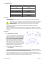
1.4.1 Installation Accessories
THI offers a complete line of system attachments that
permit easy maintenance for contaminated operations.
Gauge tubes are offered with various system fittings to
match almost any system requirement. Additionally,
THI’s complete line of quick disconnect attachments
allows customers to install these special fittings and
easily replace sensors without vacuum sealant or
Teflon® tape. For particularly dirty systems, Hastings
offers a particle dropout trap containing a series of nine
separate baffles which prevent solid contaminants from
having a direct path to the sensor’s thermopile.
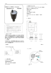
1.4.2 DV-6S: New DV-6 tube For Severe
Environments
Hastings Instruments has developed a new gauge tube, the DV-6S, which is specifically designed for
outdoor use on cryogenic tanks including railcar and tanker truck applications. In addition to the DAVC, the
gauge tube is compatible with the hand-held HPM-4/6 and the analog VT-6.
The DV-6S is supplied with a protective cap. The o-ring-sealed cap protects the gauge tube pins from
moisture thus significantly reducing corrosion. A metal lanyard prevents cap loss. The tube is provided with
a standard 1/8” NPT fitting; however special fitting requests can often be met.
174-082010_Digital AVC
Page 5 of 17
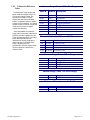
1.4.3 Calibration Reference
Tubes
THI Reference Tubes employ the
same metal thermopiles used in all
THI Vacuum Gauge Tubes. The
thermopile is sealed in a glass
capsule that has been evacuated,
baked, out-gassed, and then aged to
ensure long-term stability. The sealed
capsule is then housed in a protective
metal shell to provide a rugged,
trouble-free assembly.
Once assembled, the reference
gauge tube is accurately calibrated to
precisely simulate a gauge tube at a
given operating pressure. It provides
quick and easy instrument recalibration by merely plugging the
instrument and, in the case of the
DAVC, adjusting the HTR
potentiometer until the display reads
the exact pressure noted on the
reference tube.
Vacuum Gauge Tubes 1000 mTorr Range
Stock #
Model # Description
55-38
DV-6M
1/8” NPT Standard (Yellow base)
55-38R
DV-6R
1/8” Ruggedized
55-38RS
DV-6
1/8” NPT Rohs Rugged
55-38S
DV-6S
1/8” NPT Rugged/Vibration
55-251
DV-6-KF-16
KF-16
TM
55-267
DV-6-KF-25
KF-25
TM
TM
55-283
DV-6-VCR
VCR
55-38R-CF
DV-6R-CF
Mini Conflat
TM
Extension Cables for VT Series (DAVC)
55-3
OM-8-OFV
8 Ft Extension Cable
55-22
OM-12-OFV
12 Ft Extension Cable
65-53
OM-25-OFV
25 Ft Extension Cable
65-102 OM-50-OFV
50 Ft Extension Cable
55-142 OM-100-OFV 100 Ft Extension Cable
Vacuum Gauge Tubes 20Torr Range
55-19
DV-4D
55-19R
DV-4R
1/8” NPT (Purple Base)
1/8” NPT Ruggedized
55-258
DV-4D-KF-16
KF-16
TM
55-266
DV-4D-KF-25
KF-25
TM
55-227
DV-4D-VCR
VCR
TM
Vacuum Gauge Tubes 100 mTorr Range
55-19
DV-5M
1/8” NPT (Red Base)
55-230
DV-5M -VCR
VCR
TM
Reference Tubes for use with DAVC
174-082010_Digital AVC
55-104
DB-20
Ref Tube (DV-6) for DAVC-6 Calibration
55-101
DB-16D
Ref Tube (DV-4D) for DAVC-4 Calibration
55-103
DB-18
Ref Tube (DV-5) for DAVC-5 Calibration
Page 6 of 17
2.0 Installation
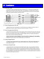
2.1 Power-I/O Cable
The Power-I/O Cable is assembled at the factory as shown in Fig. 1. Its terminal end is finished with
stripped wire ends each tinned with lead free solder. This configuration is consistent with the previous,
analog version of the AVC and its color coded wire assignment remains the same, as much as possible,
considering the additional features of the Digital version.
Fig 1
2.2 Power Requirements & Pin Out
Supply the DAVC with a well regulated, 12 to 30 VDC power source capable of providing at least 0.5.
Watts between Power pin 4 (blue/-) and Power Common pin 3 (green/+). See Fig. 1.
2.3 Serial Communications Pin Out
The transmit line of the DAVC, RS232 TX pin 15 (pink), must be connected to the receive pin of the serial
connector on the computer and the receive line, RS232 RX pin 14 (tan) must be connected to the transmit
pin of the serial connector on the computer. A third line, Digital Common, pin 8 (black), should join the
common pins on both the computer and the DAVC.
RS-232 communication may be established with baud rates of 9600 or 19200 only. The communication
conditions of the DAVC are fixed at 8 data bits, 1 stop bit, no parity and no handshaking. See the SERIAL
COMMUNICATIONS subsection under OPERATION for the command set.
2.4 Analog Output Pin Out
An analog Pressure Signal output line, pin 7 (yellow) supplies a 0 to 1 VDC signal corresponding to the
output range of the selected tube. This signal should be measured with respect to the Analog Signal
Common at pin 6 (violet).
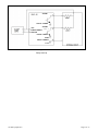
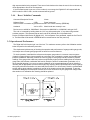
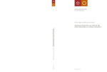
2.5 Pressure Alarms Pin Out
A single pressure set point controls two open collector circuits. Alarm 1, the over-pressure condition is
available through pin 1 (gray) and Alarm 2, the under-pressure condition available through pin 2 (brown).
The open-collector circuits will need to be supplied with power and current limiting resistance by the end
user. The suggested circuit configuration is illustrated in Figure 2. The open collector circuits are limited to
the Voltage limitations of the DAVC and the maximum continuous current should be limited to no more than
0.5 amps to avoid damage to the DAVC.
174-082010_Digital AVC
Page 7 of 17
ALARM 1
DIGITAL COMMON
ALARM 2
+VDC
POWER COMMON
DIGITAL COMMON
DIGITAL COMMON
Fig. 2
Relay Hook Up
174-082010_Digital AVC
Page 8 of 17
3.0 Vacuum Gauge Operation
All THI gauge tubes are shipped with a protective cap or cover at the evacuation port to reduce
contamination and prevent damage to the internal thermopile elements. Once the protective cap or cover is
removed, a tube can be installed in any convenient position in the vacuum system without adversely
affecting calibration or performance. The recommended orientation is with the tube vertical and its stem
down. This will aide in preventing condensable materials from remaining in the gauge tube.
3.1 Quick Start
1. Install the appropriate DV4, DV5 or DV6 gauge tube (See the bottom of the instrument to determine
the appropriate tube) into the vacuum system. When installing the gage tube, consider the position
of the keyed octal plug so that the LED’s and controls on the DAVC will be readily accessible
2. Plug the gauge tube into the octal socket on the bottom of the Digital AVC.
3. Connect power common (-) to the blue wire (pin 4) and from +12 VDC to +30 VDC supply to the
green wire (pin 3). One of the LED's indicating over-pressure or under-pressure on the top of the
DAVC will illuminate.
4. While at one atmosphere, press the ATM button and release to set the atmosphere tube output for
this individual tube. The LEDS will flash while the button is pressed. Holding the button longer than
3 seconds will reset the adjustment back to the default value.
5. The low pressure accuracy can be improved if the vacuum chamber can be pumped down below the
minimum pressure range of the attached tube can be reached, adjust the HTR potentiometer until
that pressure reading is reported (See the serial communication section) or until the analog Pressure
Signal Output, pin 7 (yellow) equals approximately 1.0 Volts. Refer to Section 3.7 for more
information about tube calibration.
3.2 Analog Pressure Measurement
An analog Pressure Signal Output line, pin 7 (yellow), supplies a 0 to 1 VDC signal corresponding to the
output range of the selected tube. This signal should be measured with respect to the Analog Signal
Common line, pin 6 (violet). See the INSTALLATION section for a diagram showing the Analog Signal pin
out.
174-082010_Digital AVC
Page 9 of 17
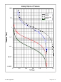
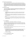
This signal is equal to an amplified tube millivolt signal. This signal will NOT be linearly proportional to
the indicated pressure. 1 volt (1.2 for DAVC4-1.2V) will correspond to a system pressure that is at least 1
order of magnitude less than the minimum detectable pressure. Increasing pressure will be indicated by a
decreasing voltage. The minimum detectable pressure is 0.2 millitorr for DAVC-5, 1 millitorr for DAVC-6
and 20 millitorr for DAVC-4.
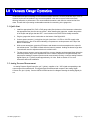
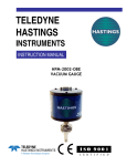
The voltage signal can be mapped to a pressure value by using the following equation.
P=
a + cV + eV 2
1 + bV + dV 2
Where:
V = Voltage
P = pressure in Torr for DV4 & DV5 versions and millitorr for DV6
Parameters
a
b
c
d
e
174-082010_Digital AVC
DV6
-1623.22
-58.0442
-11732.2
-130.397
13338.17
DV4
-5.10184
-6.91233
-4.4943
-6.30995
9.563177
DAVC-4-1.2V
-3.8115614
-2.5905928
-26.238798
-22.881611
24.483441
DV5
-0.25948
-42.23869
-2.92598
-256.99510
3.18016
Page 10 of 17
Analog Output vs Pressure
100
DAVC6
DAVC4
DAVC4-1.2V
10
DAVC5
Pressure (Torr)
1
0.1
0.01
0.001
0.0001
0
174-082010_Digital AVC
0.2
0.4
0.6
Voltage
0.8
1
1.2
Page 11 of 17
3.3 Alarm Set point
A single set point controls two open collector circuits. Though not the mechanical relays, the two circuits
called Alarm 1 (P > SP) and Alarm 2 (P < SP) allow physical monitoring of the state of the vacuum with
respect to the set point.
Alarm 1 (P > SP), pin #1 (gray), is active when the red LED is ‘ON’ indicating that the pressure is
above the set point.
Alarm 2 (P < SP), Pin #2 (brown), is active when the green LED is ‘ON’ indicating that the pressure is
below the set point.
The open-collector circuits need to be supplied with their own power and current limiting resistance by the
end user. The load, controlled by the Open-Collector circuits, must not require voltages higher than those
specified for the DAVC (12 – 30 VDC) AND must not exceed 500 mAmps of continuous current. See the
section on Pressure Alarms Pin Out for wiring instructions.
The alarm set point may be set in one of two ways:
One, by the measuring the Voltage signal between Analog Signal Common, Pin #6 (violet) and
Setpoint Level, Pin #5 (white) and setting the voltage using the SP potentiometer until the voltage
corresponds to the pressure indicated on one of the Pressure Vs. Voltage charts above.
Two, by using the A2 command to send the set point voltage to the A/D converter in conjunction with
a P1 command to enable streaming while the pot is set to the desired trigger pressure. Remember to
disable streaming by issuing a P0 command and reset the signal source of the A/D converter by
issuing an A0 command.
While the SP potentiometer is enabled using the PE command, the value of the set point is read every
thirty seconds and compared to its previous setting. If the setting has changed, the new setting will be
stored to non-volatile memory. If the SP potentiometer is disabled using the PD command, then no
tweaking of the SP potentiometer will have any affect.
In either Enabled (PE) or Disabled (PD) cases, using the S1=#.## command will re-write a new set point.
Only if the Potentiometer is Enabled using the PE command, will adjustment of the potentiometer affect a
previous set point.
3.4 Digital Communications.
See the section on Serial Communications Pin Out for wiring instructions. RS-232 communication may be
established with baud rates of 9600 or 19200 only. The communication parameters of the DAVC are fixed
at 8 data bits, 1 stop bit, no parity and no handshaking. The command set can be found in the table below.
Communication with the serial interface of the Digital AVC is via an ASCII data string. The command
message consists only of a command string and the terminator. If all components of the ASCII data string
are valid the command will be accepted and executed.
3.4.1 Command Syntax.
In the following examples of syntax codes, the special characters are explained:
The first characters in each row of the format column represent a command string, either upper or lower
case command characters accepted. All characters must follow each other in the string with no spaces
or other characters.
The characters within wavy brackets { } contain choices for the appropriate command.
The characters within the symbols < > are the common abbreviations for the one digit ASCII control
codes which they represent, (e.g. <CR> represents carriage return).
All command strings must be followed by the terminator character (carriage return <CR>, also known as
ENTER).
When a lower case character is present in an example it represents an option.
174-082010_Digital AVC
Page 12 of 17
Character
Description
Valid Inputs:
m
Most Significant Digit Of Mantissa
1-9
d
Decimal Digit
0-9
e
Exponent
0-5
<CR> Command Terminator (carriage return)
3.4.2
N/A
Interrogation Commands.
Command Description
Format
Sample Response
Get Device ID
ID<CR>
Digital AVC<CR>
Get Current Pressure if A0 is set, current Set Point
if A2 is set, heater potentiometer setting if A3 is set
P<CR>
Pa: 1.23456e+0 Torr<CR>
Get Relay Status
RS<CR>
1,R1:ON<CR>
Get Setpoint
S1<CR>
SP1: 1.0240e-2 mbar<CR>
Get Serial Number (10 character max)
SN<CR>
1023400012<CR>
Get Sensor Type
ST<CR>
DV-6<CR>
Get Raw Average Output Voltage – No Offset.
U<CR>
Vavg: 1.23456e-1 Volts<CR>
Get User Data (10 character max)
UD<CR>
TextString<CR>
Get Software Version #
V<CR>
Digital CVT 1.1.0 <CR>
3.4.3
Parameter Modification Commands
Command Description
Format
Response
notes:
Select A/D input 0
A0<CR>
none
Read from gauge tube
Select A/D input 1
A1<CR>
none
Read from Setpoint Potentiometer
Select A/D input 2
A2<CR>
none
Read heater adjust potentiometer
Data streaming/Logging Off
Data streaming/Logging On
P0<CR>
P1<CR>
none
See P cmd
Stops streaming output
(Reports signal Voltage and
pressure in Torr only)
Disable set-point pot.
PD<CR>
OK
Lock out local setpoint adjustment
Enable set-point pot.
PE<CR>
OK
Enable local setpoint adjustment
Modify Setpoint
S1={m.dd}E{+e}<CR>
OK
1.00000e-9 to 9.99999e+9
Set units to Torr
U1<CR>
OK
All subsequent values in Torr
Set units to Pascal
U2<CR>
OK
All subsequent values in Pascal
Set units to Mbar
U3<CR>
OK
All subsequent values in mbar
Modify User Data
UD=TextString<CR>
10 character maximum
Notes:
The User Data is 10 digit text area reserved for use by the customer for identification purposes.
The setpoints may also be entered as a decimal number, e.g. [S1=0.760<CR>] will be same as entering
[H=7.60E-1<CR>] .
When inputting setpoint data, it should be entered in the same Units of Pressure as the presently selected
Units of Measurement (i.e. Torr, mbar or Pascal). The data is only checked to be a valid number with a one
174-082010_Digital AVC
Page 13 of 17
digit exponent before being accepted. There are no limit checks on the data; the user is free to choose any
value appropriate to his use of the instrument.
If the command syntax is not met or if the number is out or range, the Digital AVC will respond with the
ASCII codes for <bell>?<CR>, and the command will be ignored.
3.4.4
Reset / Initialize Commands
Command Description Format
Notes:
Software Reset
/<CR>
Reset instrument
Does not reset or overwrite any parameters saved in non-volatile memory (EEPROM).
Autobaud
<ctrl-z><CR>
Match baud rate currently in use
Device can run at 9600 or 19200 Baud. Set terminal to 9600/N/8/1 or 19200/N/8/1 and type Ctrl-Z.
The <ctrl-z> is entered by holding down the “Ctrl” key while pressing the “z” key when using terminal
emulator program. This character has an ascii code of 26 (decimal) and 1A (hexadecimal).
Device will respond with Device ID (Digital AVC). If this response is not generated, repeat the Ctrl-Z until it
is. The Baud rate will be stored in EEPROM and is remembered on the next power-up.
3.5 Operation and Performance
The Digital AVC will function right “out of the box”. For maximum accuracy refer to the Calibration section
below and perform the calibration procedure.
The simplest and quickest way of checking the operation and performance of a gauge and/or gauge tube,
is to keep a new or known-good gauge tube on hand for use as a reference.
To check operation, install both the reference and suspect gauge tubes in a common vacuum system
(locate the gauge tubes as close as possible to each other), then evacuate the system until a stable base
pressure is obtained. Alternately connect the vacuum gauge to each gauge tube and record its pressure
readings. If the gauge tube-under-test produces a significantly higher pressure reading than the reference
gauge tube, this indicates a calibration shift and is usually the result of contamination (particulate, oil, or
other chemical deposits). You can try to restore calibration of the contaminated gauge tube by cleaning it
internally with an appropriate solvent such as high-purity isopropyl alcohol (flood the interior cavity of gauge
tube gently with solvent and allow it to stand and soak for about 15 to 30-minutes). Drain the contaminated
solvent and let gauge tube dry in ambient air until all of the cleaning solvent has evaporated. To prevent
mechanical damage to the thermopile elements, do not use forced air to dry the gauge tube. Gauge tubes
that remain out of calibration after cleaning should be replaced.
174-082010_Digital AVC
Page 14 of 17
3.6 Gauge Tube Operating Principle
Operation of the Hastings gauge tube is based on a low voltage AC bridge that heats a noble metal
thermopile. A change in pressure in the gauge tube changes the molecular collision rate and therefore the
thermal conduction of the gas or gas mixture surrounding the thermopile. This results in a temperature shift
in the AC heated thermocouples A and B (Fig. 6). The resultant temperature shift causes a change in the
DC output from couples A and B inversely with pressure changes. The DC thermocouple C (when installed)
is in series with the circuit load. Thermocouple C provides compensation for transient changes in ambient
temperature.
3.7 Calibration Procedure
NOTE: ONCE CALIBRATION IS COMPLETE THE CALIBRATION DATA IS PERMANENTLY STORED
IN NON-VOLATILE MEMORY. A LOSS OF POWER WILL NOT ERASE THE CALIBRATION DATA. TO
ERASE THE CALIBRATION DATA, REFER TO STEP 2.
3.7.1 Preparation
1. The following procedures can be carried out on a unit installed in a vacuum system as long as a
calibrated reference meter is installed in the same system in close proximity to the unit being
calibrated.
2. The following procedure assumes that the appropriate DV4, DV5 or DV6 gauge tube (See the
bottom of the instrument to determine the appropriate tube) corresponding to the set up of the DAVC
is connected to the unit.
3. Power the DAVC with a DC supply capable of providing from 12 to 30 Volts DC and at least 0.5
Amps.
4. Using a pointed object, such as a ballpoint pen, press and hold the “ATM” push button located on
the top cover until the two LEDS are on continuously (approximately 3 seconds). This deletes any
previously stored data.
3.7.2 Set High End
NOTE: TUBE MUST BE AT ATMOSPHERE TO PROPERLY SET THE HIGH END.
While at one atmosphere, press the ATM button and release to set the atmosphere tube output for this
individual tube. The LEDS will flash while the button is pressed. Push the button only as long as it takes
the LED’s to blink one or twice. Holding the button longer than 3 seconds will reset the adjustment back to
the default value. The high-end setting is now set.
3.7.3 Set Low End W/Vacuum System
NOTE: The LOW END can be adjusted by either bringing the system to a known vacuum or by using a
HASTINGS REFERENCE TUBE (see below).
A. Set system to known vacuum.
B. Turn the HTR potentiometer on the top panel until the either the voltage measured between pins 6,
Analog Signal Common (violet) and 7, Pressure Signal Output (yellow) reads the voltage
corresponding to the pressure as read on the Pressure Vs. Voltage chart for the tube being
measured or, if using serial communication, until the proper pressure is read while using the
streaming P1 command.
C. The low end is now adjusted.
3.7.4 Set Low End W/Reference Tube.
A. Connect the THI reference tube.
174-082010_Digital AVC
Page 15 of 17
B. Turn the HTR potentiometer on the top panel until the either the voltage measured between pins 6,
Analog Signal Common (violet) and 7, Pressure Signal Output (yellow) reads the voltage
corresponding to the pressure as read on the Pressure Vs. Voltage chart for the tube being
measured or, if using serial communication, until the proper pressure is read while using the
streaming P1 command.
C. THE LOW END is now adjusted.
NOTE: If re-calibration is required you must repeat the High End adjustment first.
The following table specifies the THI reference tube to be used in the calibration of a gauge based upon
the type of gauge tube being used.
Ref. Tube
174-082010_Digital AVC
Gauge Tube
DB-16D
DV-4
DB-18
DV-5
DB-20
DV-6
Page 16 of 17
4.0 Warranty
4.1 Warranty Repair Policy
Hastings Instruments warrants this product for a period of one year from the date of shipment to be free
from defects in material and workmanship. This warranty does not apply to defects or failures resulting from
unauthorized modification, misuse or mishandling of the product. This warranty does not apply to batteries
or other expendable parts, nor to damage caused by leaking batteries or any similar occurrence. This
warranty does not apply to any instrument which has had a tamper seal removed or broken.
This warranty is in lieu of all other warranties, expressed or implied, including any implied warranty as to
fitness for a particular use. Hastings Instruments shall not be liable for any indirect or consequential
damages.
Hastings Instruments, will, at its option, repair, replace or refund the selling price of the product if Hastings
Instruments determines, in good faith, that it is defective in materials or workmanship during the warranty
period. Defective instruments should be returned to Hastings Instruments, shipment prepaid, together
with a written statement of the problem and a Return Material Authorization (RMA) number. Please consult
the factory for your RMA number before returning any product for repair. Collect freight will not be
accepted.
4.2 Non-Warranty Repair Policy
Any product returned for a non-warranty repair must be accompanied by a purchase order, RMA form and
a written description of the problem with the instrument. If the repair cost is higher, you will be contacted for
authorization before we proceed with any repairs. If you then choose not to have the product repaired, a
minimum will be charged to cover the processing and inspection. Please consult the factory for your RMA
number before returning any product repair.
TELEDYNE HASTINGS INSTRUMENTS
804 NEWCOMBE AVENUE
HAMPTON, VIRGINIA 23669 U.S.A.
ATTENTION: REPAIR DEPARTMENT
TELEPHONE
(757) 723-6531
1-800-950-2468
FAX
(757) 723-3925
E MAIL
mailto:[email protected]
INTERNET ADDRESS
http://www.teledyne-hi.com
Repair Forms may be obtained from the “Information Desk” section of the Hastings Instruments web site.
174-082010_Digital AVC
Page 17 of 17