1
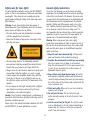
INSTRUCTION MANUAL
1/2 HP 12 Speed
Drill Press
with Laser Line Generator*
* Patent Pending
• Melbourne • Perth • Auckland • Hong Kong • Shanghai
• Taipei • New York • Verona • London • Paris
LDP13B
040614 ED3 JJ
Contents
Warranty
Introduction
Environmental protection
Description of symbols
Specifications
Safety rules for laser lights
General safety instructions
Additional safety rules for drill presses
Unpacking
Required tools
Assembly time
Accessories
Know your product
Assembly
Adjustments
Adjusting the table height
Adjusting the table angle
Extension tables
Tool storage drawer
Installing and removing drill bits
Setting the drilling depth
Changing the speed
Turning on and off
Turning on the REDEYE® laser line generator
Adjusting the laser
Operation
Wood drilling
Metal drilling
Maintenance
Cleaning
General inspection
Repairs
Troubleshooting
Full 2 Years Home Use Warranty
2
3
3
3
3
4
4
6
7
7
7
8
9
10
11
11
11
12
12
12
12
13
14
14
14
14
15
15
15
15
15
15
16
Whilst every effort is made to ensure your complete
satisfaction with this tool, occasionally, due to the mass
manufacturing techniques, a tool may not live up to our
required level of performance and you may need the
assistance of our service department.
This product is warranted for a 2-year period for home
domestic use from the date of the original purchase. If
found to be defective in materials or workmanship, the
tool or the offending faulty component will be replaced
free of charge with another of the same item. A small
freight charge may apply.
The warranty replacement unit is only made available by
returning the tool to the place of purchase with a
confirmed register receipt. Proof of purchase is essential.
We reserve the right to reject any claim where the
purchase cannot be verified.
This warranty does not include damage or defects to the
tool caused by or resulting from abuse, accidents,
alterations or commercial or business use.
It also does not cover any bonus accessories unless the
tool is a GMC Platinum Professional model.
Please ensure that you store your receipt in a safe place.
Conditions apply to the above warranty.
If you need direction of what constitutes a free of
charge warranty claim, please review the guide given on
the rear of the Receipt Holder. An indication is given as
to the types of claim that are permissible, and those
that are not.
2
Symbols
Dear Customer
The rating plate on your tool may show symbols. These
represent important information about the product or
instructions on its use.
Wear hearing protection.
Wear eye protection.
Wear breathing protection.
If you require any help with your product, whether it
is a Warranty claim, spare part or user information,
please phone our Help Line for an immediate response.
Phone 1300 880 001 in Australia or 0800 445 721 in
New Zealand.
Introduction
Conforms to EMC regulations.
Your new GMC power tool will more than satisfy your
expectations. It has been manufactured under stringent
GMC Quality Standards to meet superior performance
criteria.
You will find your new tool easy and safe to operate,
and, with proper care, it will give you many years of
dependable service.
Caution. Carefully read through this entire Instruction
Manual before using your new GMC Power Tool. Take
special care to heed the Cautions and Warnings.
Your GMC power tool has many features that will make
your job faster and easier. Safety, performance, and
dependability have been given top priority in the
development of this tool, making it easy to maintain
and operate.
Specifications
Nominal voltage:
Power:
Chuck capacity:
Chuck type:
Spindle axis to column distance:
Maximum spindle travel:
Speed ranges:
Laser class:
Laser wavelength:
Laser output power:
Environmental protection
Recycle unwanted materials instead of
disposing of them as waste. All tools, hoses
and packaging should be sorted, taken to
the local recycling centre and disposed of
in an environmentally safe way.
Warnings.
It may be more difficult to see the laser line in conditions
of bright sunshine and on certain surfaces.
3
230–240Vac ~ 50Hz
375W
13mm
Keyless
125mm
60mm
230, 330, 370, 460,
530, 580, 1030,
1160, 1280, 1600,
1790, 2470 RPM
1
650nm
≤1Mw
Safety rules for laser lights
General safety instructions
The laser light/laser radiation used in the GMC REDEYE®
system is Class 1 with maximum 1mW power and 650nm
wavelengths. These lasers do not normally present an
optical hazard, although staring at the beam may cause
flash blindness.
Warning. Do not stare directly at the laser beam. A
hazard may exist if you deliberately stare into the beam,
please observe all safety rules as follows;
• The laser shall be used and maintained in accordance
with the manufacturer’s instructions.
• Never aim the beam at any person or an object other
than the work piece.
To use this tool properly, you must observe the safety
regulations, the assembly instructions and the operating
instructions to be found in this Manual. All persons who
use and service the machine have to be acquainted with
this Manual and must be informed about its potential
hazards. Children and infirm people must not use this
tool. Children should be supervised at all times if they
are in the area in which the tool is being used. It is
also imperative that you observe the accident prevention
regulations in force in your area. The same applies for
general rules of occupational health and safety.
Warning. When using power tools, basic safety
precautions should always be taken to reduce the risk of
fire, electric shock and personal injury. Also, please read
and heed the advice given in the additional important
safety instructions.
1. Keep the work area clean and tidy. Cluttered work
areas and benches invite accidents and injury.
2. Consider the environment in which you are working.
Do not use power tools in damp or wet locations.
Keep the work area well lit. Do not expose power tools
to rain. Do not use power tools in the presence of
flammable liquids or gases.
3. Keep visitors away from the work area. All visitors
and onlookers, especially children and infirm persons,
should be kept well away from where you are working.
Do not let others in the vicinity make contact with the
tool or extension cord.
4. Store tools safely. When not in use, tools should be
locked up out of reach.
5. Do not force the tool. The tool will do the job
better and safer working at the rate for which it was
designed.
6. Use the correct tool for the job. Do not force small
tools or attachments to do the job best handled by a
heavier duty tool. Never use a tool for a purpose for
which it was not intended.
LASER LIGHT. LASER RADIATION
Do not stare into beam.
Only turn laser beam on when tool
is on work piece. Class 1 laser product
• The laser beam shall not be deliberately aimed at
personnel and shall be prevented from being directed
towards the eye of a person for longer than 0.25s.
• Always ensure the laser beam is aimed at a sturdy work
piece without reflective surfaces. i.e. wood or rough
coated surfaces are acceptable. Bright shiny reflective
sheet steel or the like is not suitable for laser use as
the reflective surface could direct the beam back at the
operator.
• Do not change the laser light assembly with a different
type. Repairs must only be carried out by the laser
manufacturer or an authorised agent.
Caution. Use of controls or adjustments or performance of
procedures other than those specified herein may result in
hazardous radiation exposure.
Please refer to the relevant Australian standards, AS 2397
and AS/NZS2211 for more information on Lasers.
4
7. Dress correctly. Do not wear loose clothing or
jewellery. They can be caught in moving parts. Rubber
gloves and non-slip footwear are recommended when
working outdoors. If you have long hair, wear a
protective hair covering.
8. Use safety accessories. Safety glasses and earmuffs
should always be worn. A face or dust mask is also
required if the sanding operation creates dust.
9. Do not abuse the power cord. Never pull the cord to
disconnect the tool from the power point. Keep the
cord away from heat, oil and sharp edges.
10. Secure the work piece. Use clamps or a vice to hold
the work piece. It is safer than using your hand and
frees both hands to operate the tool.
11. Do not overreach. Keep your footing secure and
balanced at all times.
12. Look after your tools. Keep tools sharp and clean for
better and safer performance. Follow the instructions
regarding lubrication and accessory changes. Inspect
tool cords periodically and, if damaged, have them
repaired by an authorised service facility. Inspect
extension cords periodically and replace them if
damaged. Keep tool handles dry, clean and free from
oil and grease.
13. Disconnect idle tools. Switch off the power and
disconnect the plug from the power point before
servicing, when changing accessories and when the
tool is not in use.
14. Remove adjusting keys and wrenches. Check to see
that keys and adjusting wrenches are removed from
the tool before switching on.
15. Avoid unintentional starting. Always check that the
switch is in the OFF position before plugging in the
tool to the power supply. Do not carry a plugged in
tool with your finger on the switch.
16. Use outdoor rated extension cords. When a tool
is used outdoors, use only extension cords that are
intended for outdoor use and are so marked.
17. Stay alert. Watch what you are doing. Use common
sense. Do not operate a power tool when you are tired.
18. Check for damaged parts. Before using a tool,
check that there are no damaged parts. If a part is
slightly damaged, carefully determine if it will operate
properly and perform its intended function. Check for
alignment of moving parts, binding of moving parts,
breakage of parts, proper mounting and any other
conditions that may affect the operation of the tool.
A part that is damaged should be properly repaired
or replaced by an authorised service facility, unless
otherwise indicated in this Instruction Manual.
Defective switches must be replaced by an authorised
service facility. Do not use a tool if the switch does
not turn the tool on and off correctly.
19. Guard against electric shock. Prevent body contact
with grounded objects such as water pipes, radiators,
cookers and refrigerator enclosures.
20. Use only approved parts. When servicing, use only
identical replacement parts. Use an authorised service
facility to fit replacement parts.
5
Additional safety rules for drill presses
Warning. For your own safety, do not try to use your drill
press or plug it in until it is completely assembled and
installed according to the instructions and until you have
read and understood the following:
1. Your drill press must be bolted securely to a workbench.
In addition, if there is any tendency for your drill press
to move during certain operations, bolt the workbench
to the floor.
2. This drill press is intended for use in dry conditions and
indoor use only.
3. Always wear safety goggles which comply to a
recognised standard. Use a face or dust mask along
with safety goggles if the drilling operation is dusty.
Use ear protectors, especially during extended periods
of operation.
4. Do not try to drill material too small to be securely
held. Do not drill material that does not have a flat
surface unless it is clamped securely.
5. Always keep hands out of the path of the drill bit.
Avoid awkward hand positions where a sudden slip
could cause your hand to move into the drill bit.
6. Do not install or use any drill bit that exceeds 175mm
(7 inches) in length or extends more than 150mm (6
inches) below the chuck jaws. They can suddenly bend
outwards or break.
7. Do not use wire wheels, router bits, shaper cutters,
circle (fly) cutters or rotary planers on this drill press.
8. When cutting a large piece of material make sure it is
fully supported at the table height.
9. Do not perform any operation freehand. Always hold the
workpiece firmly against the table so it will not rock or
twist. Use clamps or a vise for unstable workpieces.
10. Make sure there are no nails or foreign objects in the
part of the workpiece to be drilled.
11. Whenever possible, position the workpiece to contact
the left side of the column; if it is too short or the
table is tilted, clamp solidly to the table.
12. If the workpiece overhangs the table such that it will
fall or tip if not held, clamp it to the table or provide
auxiliary support.
13. Set the drill press to a speed appropriate to the job.
14. Do not start the drill press while the drill bit is
touching the workpiece.
15. When using a drill press vise, always fasten it to the
table.
16. Make sure all clamps and locks are firmly tightened
before drilling.
17. Securely lock the head and table support to the
column, and the table to the table support before
operating your drill press.
18. Never turn your drill press on before clearing the table
of all objects (tools, scraps of wood etc.)
19. Before starting the operation, jog the motor switch to
make sure the drill bit does not wobble or vibrate.
20. Let the spindle reach full speed before starting to
drill. If your drill press makes an unfamiliar noise or
if it vibrated excessively, stop immediately, turn the
drill press off and unplug it. Do not restart until the
problem is corrected.
21. Do not perform layout assembly or setup work on the
table while the drill press is in operation.
22. Do not exceed the rpm stated on the bit or accessory.
See the instructions that come with the accessory.
23. When drilling large diameter holes, clamp the
workpiece firmly to the table. Otherwise, the bit may
grab and spin the workpiece at high speed. Do not use
fly cutters or multiple-part cutters, as they can come
apart or become unbalanced in use.
24. Make sure the spindle has come to a complete stop
before touching the workpiece.
25. To avoid injury from accidental starting, always
turn the switch off and unplug the drill press before
installing or removing any accessory attachment or
making any adjustment.
6
Caution! Do not expose to rain or use in damp locations.
Warning! For your own safety read instruction manual
before operating drill press. Wear eye protection, do not
wear gloves, necktie or loose clothing, clamp workpiece
or brace against column to prevent rotation, use
recommended speed for drill accessory and workpiece
material.
Required tools
Unpacking
The LDP13B drill press will take approximately 20 minutes
to assemble.
The following tools are required to assemble the drill press
• 3mm, 4mm, 6mm Hex Keys (Supplied)
• Wrench (Not Supplied)
• Phillips Head Screwdriver (Not Supplied)
Assembly time
Due to modern mass production techniques, it is unlikely
that your GMC Power Tool is faulty or that a part is
missing. If you find anything wrong, do not operate the
tool until the parts have been replaced or the fault has
been rectified. Failure to do so could result in serious
personal injury.
7
Accessories
The LDP13B is supplied with the following components:
1. Base
2. Column
3. Rack
4. Rack Collar
5. Table
6. Belts (x2)
7. Handle
8. Keyless Chuck
9. Extension Table Locking Knobs (x4)
10. Motor Head
11. Handle
12. Depth Scale
13. Table Lock
14. Worm
15. Hex Keys (x3)
16. Bolts for attaching column to base (x4)
17. Bolt to attach handle
8
13
1
2
5
9
15
8
4
6
10
14
3
11
7
12
16
17
Know your product
1. Laser light on/off switch
2. Laser aperture (x2)
3. On/off switch
4. Pulley cover
5. Base
6. Column
7. Rack
8. Rack Collar
9. Table/Support Assembly
10. Belts (x2)
11. Belt Tension Lever
12. Table Handle
13. Keyless Chuck
14. Extension Table
Locking Knobs (x4)
15. Motor Head
16. Feed Handle
17. Depth Gauge
18. Depth Scale/Lock
19. Table Lock
20. Bevel Scale
21. Hex Keys
1
18
4
11 10
10
3
15
17
16
2
19
13
8
7
9
6
12
20
14
5
21
9
Assembly
1. Place base on floor.
2. Place column assembly on
base and align the 4 holes
in the column assembly with
the holes in the base.
3. Using the 4 8mm diameter
x 20mm long bolts secure
the column support to the
base and tighten with
a wrench.
4. Loosen the screw on the rack
collar using the 4mm hex key.
5. Remove the rack collar by
lifting it up and over the
column.
6. Remove the rack from the
column.
7. Ensure that the 4 knobs
securing the extension tables
are tight.
8. Fully insert the worm gear
shaft into the table support
and engage it on the gear
wheel in the assembly.
9. With the short smooth
section of the rack pointing
downwards, slide the rack
through the round opening
in the table support.
10. Engage the rack on the
gear mechanism found
inside the opening of the
table support.
11. Whilst holding the rack and table support slide both
over the column. Slide the rack down until the rack is
positioned against the lower column support.
12. Fit the rack collar over the
column and bring it down
to the top of the rack.
Ensure the bevel side is
down over the rack.
13. Tighten the rack collar
using the 4mm hex key.
To let the rack slide when
the table is swung left or
right around the column
only tighten the set screw
enough to keep the collar
in place.
14. Fit the motor head over
the column and tighten
the 2 grub screws using
the 4mm hex key. This will
secure the head on the
column.
15. Attach the table handle to the worm drive shaft and
tighten the grub screw using the 4mm hex key.
10
16. Fit the table lock into the
table support assembly and
tighten to secure the table.
17. Fit the depth scale/lock
onto the handle.
18. Fit the handle and depth
scale onto the motor head
ensuring that the flats on
the handle locate the flats
on the shaft.
19. Secure the handle onto the
motor head by placing the
handle bolt through the
middle of the handle and
secure it with the 6mm hex
key.
20. Fit the chuck onto the
spindle and secure it by
pushing it and giving it a
sharp tap.
Note. Ensure both surfaces are
clean before putting the chuck
on the spindle.
21. Place a screwdriver through
the top of the pulley cover,
loosen and remove the
screw securing the pulley cover. Lift off the cover.
Note. Fit the lower belt on first.
Note. When fitting belts it is
easier to place the belt onto
the small pulley and then turn
it onto the larger pulley.
23. To tighten the belts on
the pulleys pull the motor
backwards. This is best
done by grabbing hold of
the top of the rear pulley
and the bottom of the
motor housing.
24. To loosen the motor and
reduce the belt tension
pull the belt tension lever
towards the motor and
push motor forwards.
25. Replace and secure the
pulley cover.
Adjustments
Adjusting the table height
Caution. Always ensure that
the drill press is switched off
and the plug is removed from
the power point before making
any adjustments.
1. Loosen the table lock.
2. Rotate the handle in a clockwise direction to raise the
table.
3. Rotate the handle in an anti-clockwise direction to
lower the table.
4. Tighten the table lock to secure the table.
Adjusting the table angle
Caution. Always ensure that the drill press is switched
off and the plug is removed from the power point before
making any adjustments.
22. Fit the belts over the pulleys, refer to the inside of the
cover for speed reference.
11
1. Loosen the screw under the table by rotating it in an
anti-clockwise direction.
2. Tilt the table to the desired angle as indicated on the
bevel scale.
Tool storage drawer
The tool storage drawer is handy for storing hex keys, drill
bits and accessories.
Installing and removing drill bits
Caution. Always ensure that the drill press is switched
off and the plug is removed from the power point before
making any adjustments.
1. Loosen the chuck sufficiently so that the jaws are open
wide enough to allow a bit to be inserted. The chuck is
loosened by rotating the collar in a clockwise direction.
3. Tighten the screw under the table by rotating it in a
clockwise direction.
Note. When the table is tilted the work piece should be
clamped to the table.
Extension tables
Caution. Always ensure that the drill press is switched
off and the plug is removed from the power point before
making any adjustments.
1. The extension tables are handy when working with larger
work pieces and allow the table size to be increased for
greater material support.
2. Place the bit into the open chuck as far as it will go.
3. Tighten the chuck by rotating the collar in an anticlockwise direction.
4. To remove the bit, loosen the chuck by rotating the
collar in a clockwise direction.
Setting the drilling depth
2. To adjust the extension table loosen the 2 knobs on the
underside of the work table.
3. Extend the extension table to the desired width.
4. Tighten the 2 knobs to secure the extension table in
position.
Caution. Always ensure that the drill press is switched
off and the plug is removed from the power point before
making any adjustments.
1. Loosen the handle screw half
a turn using 6mm hex key
2. Ensuring the drill bit is tight
in the chuck use the feed
wheel to lower the spindle
until the drill bit just touches
the work piece.
12
in
0
1
1/2 HP
LDP13B Drill Press with Laser Line
230V–240Vac ~ 50Hz 375W no. 230–2470 RPM
Ø13mm EARTHED APPLIANCE
Always wear ear and eye protection. If cordset is damaged
have it replaced by an authorised service centre.
Help Line 1300 880 001 (Aus) or 0800 445 721 (NZ)
Product of China to GMC Quality Standards
3. Holding the handle in that position rotate the depth
scale to the desired drilling depth.
1. Remove the plug from the mains socket.
2. Take off the pulley cover.
3. Loosen the motor and reduce
the belt tension by pulling
the belt tension lever towards
the motor and pushing motor
forwards.
4. To select a faster drill speed,
move the belt up to a higher
step on the front and central
pulleys and lower step on
the central and rear pulleys.
Rotating the pulleys and
“rolling” the belt onto the
larger pulley will make this
easier.
5. To select a slower drill speed,
move the belt down to a
smaller step on the front and
central pulleys and a higher
step on the central and rear pulleys. Rotating the pulleys
and “rolling” the belt onto the larger pulley will make
this easier.
6. To tighten the belts on
in
the pulleys
pull the motor
0
0
backwards. This is best done
by grabbing hold of the top
10
of the rear
pulley and the
bottom of the motor housing.
20 pulley by hand to
7. Rotate the
ensure1everything is aligned
and correct.
30
8. Replace the pulley cover.
2
LASER LIGHT. LASER RADIATION
Do not stare into beam.
Only turn laser beam on when tool
is on work piece. Class 1 laser product
4. Tighten the handle screw
firmly to secure the handle
in position.
5. Lift the handle up and then
proceed with the drilling
operation.
6. To disable the depth lock
loosen the handle screw and
rotate the depth scale to the maximum depth.
7. Tighten the handle screw firmly to secure the handle
in position.
45º40º
30º 20º 10º
0º
10º
20º 30º 40º45º
Changing the speed
ck & Pinion
Caution. Always ensure that the drill press is switched
off and the plug is removed from the power point before
making any adjustments.
The speed of the drill press is determined by the size of the
pulley steps that the belt is attached to. Using a smaller
pulley step on the front pulley means a faster drill speed;
using a larger pulley step on the front pulley means a
slower drill speed. The below table indicates the speed of
the drill in the various belt positions.
230
330
370
460
530
580
1030
1160
1280
1600
1790
2470
mm
40
2
50
60
13
Turning on and off
Adjusting the laser
1. To start the drill press insert
the switch disabling insert
and move the switch up to
the ‘ON’ position.
2. Move the switch down to the
‘OFF’ position to turn the drill
press off.
3. Remove the switch disabling
insert to prevent unauthorised
use and store it in a secure
location out of reach of
children.
1. Clamp a scrap piece of
material to the table.
2. Insert a drill bit into the
chuck jaws.
3. Turn on the drill press.
4. Using the feed wheel lower
the spindle and make a small
mark in the workpiece.
5. Turn on the laser line generator.
6. If the laser is not aligned
with the mark in the work
piece, adjust as follows.
7. Using the 3mm hex key
loosen the set screw that
secures the laser light
assembly.
8. Rotate the laser beam until
it intersects the mark in the
workpiece.
9. Repeat the process for the
other side.
Turning on the REDEYE® laser line generator
1. The REDEYE® laser line generator emits two intense
narrow beams of pure red light that intersect at the
drilling point.
2. The intersection is clearly visible and will not be
obscured by dust. It improves operator drilling vision,
enables faster set-up, increases accuracy and improves
safety.
3. To turn the laser line on move
the switch to the ‘I’ position.
4. To turn off the laser line move
the switch to the ‘O’ position.
Operation
Caution. Always ensure that the drill press is switched
off and the plug is removed from the power point before
making any adjustments.
Caution. For through drilling always ensure that the hole
in the centre of the table is aligned with the drill bit.
Warning. On start-up over-tightening the belts may
prevent the drill press from starting.
Warning. Don’t force the drill, allow the drill bit to do the
work.
14
1. Adjust the table height, table angle, drilling depth and
speed as required for the application.
2. Insert the drill bit required for the application.
3. Mark the drilling points on the work piece.
4. Switch on the laser line and line up with the drilling
point with the intersection point of the two beams.
5. Where possible secure the workpiece in position with vice
or clamps.
6. Turn on the drill press using the on/off switch.
7. Rotate the feed wheel to bring the drill bit down to the
workpiece.
8. Apply pressure to the feed wheel and slowly drill through
the workpiece. Don’t force the drill, allow the drill bit to
do the work.
9. After drilling the hole release the feed wheel and allow
the spindle to return to its original position.
10. Turn off the drill press.
11. Turn off the laser line generator.
• Maintain a speed and pressure which allows cutting
without overheating the bit. Applying too much pressure
will:
• Overheat the drill
• Wear the bearings
• Bend or burn bits
• Produce off-centre or irregular shaped holes
• When drilling large holes in metal it is recommended to
drill with a small bit at first, then finish with a larger bit.
Also, lubricate the bit with oil to improve drilling action
and increase bit life.
Maintenance
Warning. Always ensure that the tool is switched off and
the plug is removed from the power point before making
and adjustments or maintenance procedures.
Cleaning
1. Keep the tool’s air vents unclogged and clean at all times.
2. Remove dust and dirt regularly. Cleaning is best done
with a soft brush or a rag.
3. Re-lubricate all moving parts at regular intervals.
4. Never use caustic agents to clean plastic parts.
Caution. Do not use cleaning agents to clean the plastic
parts of the tool. A mild detergent on a damp cloth is
recommended.
Wood drilling
• For maximum performance, use high speed steel bits for
wood drilling.
• Secure the workpiece to prevent it from turning when
drilling.
• When drilling through holes, place a block of wood
behind the workpiece to prevent ragged or splintered
edges on the back side of the hole.
General inspection
Regularly check that all the fixing screws are tight. They
may vibrate loose over time.
Metal drilling
Repairs
• For maximum performance, use high speed steel bits for
metal or steel drilling.
• Use a centre punch to mark the hole location on the
workpiece.
Only an authorised service centre should replace the
cordset or effect other repairs. If the cordset is damaged or
worn, have it repaired or replaced by an authorised service
centre.
15
Troubleshooting
Warning. Turn the on/off switch to the off position and
unplug the tool from the power supply before performing
trouble shooting procedures.
Troubleshooting
Problem
Cause
Solution
Drill press will not start
Power cord not plugged in
Ensure that the cord is connected to the
power supply
Power fault, fuse or circuit breaker tripped
Check the power supply
Cord damaged
Use authorised service centre to repair or
replace
Faulty switch
Use authorised service centre to repair or replace
Faulty motor
Use authorised service centre to repair or
replace the motor
Noisy operation
Incorrect belt tension
Adjust tension as required
Drill bit burns
Incorrect speed
Change speed, refer to the “Changing the
speed” section
Chips not coming out of hole
Retract drill bit frequently to clear holes
Dull drill bit
Resharpen or replace drill bit
Bent drill bit
Replace with new drill bit
Drill bit not properly installed in chuck
Install drill bit properly and ensure it is secure
Excessive drill bit wobble
Chuck not properly installed
Install chuck properly
Wood splinters under workpiece
No “packing” material below workpiece
Use “packers” below the workpiece
Workpiece torn from hand
Workpiece not supported or clamped properly
Support the workpiece or clamp it
Drill bit binds in workpiece
Improper belt tension
Adjust the belt tension
16
Carefully read the entire Instruction Manual
before using this product.
Before returning this product for a
Warranty Claim or any other reason
Please Call 1300 880 001 (Australia)
or 0800 445 721 (New Zealand)
With continuing product development changes may
have occurred which render the product received
slightly different to that shown in this instruction
manual. The manufacturer reserves the right to
change specifications without notice. Note:
Specifications may differ from country to country.
When you make your call, please have
the following information at hand:
• GMC Product Type • GMC Product Code
A GMC Service Engineer will take your call and, in
most cases, will be able to solve your problem over
the phone.
The GMC 777 Helpline operates from 7am to
7pm, 7 days a week (EST). This allows you
to contact GMC directly with any queries and
technical questions you have regarding
our products.
You are welcome to use this phone-in service to
make suggestions or give comments about any
GMC product.
45–55 South Centre Road
Melbourne Airport
Victoria, Australia 3045
Tel: (03) 8346 1100 Fax: (03) 8346 1200
Save this Manual for future reference.
17