1
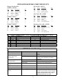
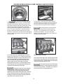
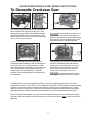
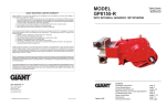
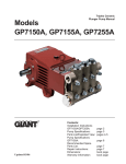
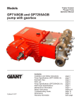
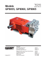
Triplex Ceramic Plunger Pump Models Manual Models GP8055, GP8060, GP8065 Updated 3/07 Contents: Installation Instructions: Pump Specifications: Exploded View/Parts List: Repair Kits/Tool List:/Torque Specifications Troubleshooting Chart: Repair Instructions: Dimensions: Warranty Information page 2 page 3-5 pages 6-7 page 8 page 8 pages 9-11 back page back page INSTALLATION INSTRUCTIONS Installation of the Giant Industries, Inc., pump is not a complicated procedure, but there are some basic steps common to all pumps. The following information is to be considered as a general outline for installation. If you have unique requirements, please contact Giant Industries, Inc. or your local distributor for assistance. 5. Crankshaft rotation on Giant Industries, Inc. pumps should be made in the direction designated by the arrows on the pump crankcase. Reverse rotation may be safely achieved by following a few guidelines available upon request from Giant Industries, Inc. Required horsepower for system operation can be obtained from the charts on pages 3- 6. 1. The pump should be installed flat on a base to a maximum of a 15 degree angle of inclination to ensure optimum lubrication. 6. Before beginning operation of your pumping system, remember: Check that the crankcase and seal areas have been properly lubricated per recommended schedules. Do not run the pump dry for extended periods of time. Cavitation will result in severe damage. Always remember to check that all plumbing valves are open and that pumped media can flow freely to the inlet of the pump. 2. The inlet to the pump should be sized for the flow rate of the pump with no unnecessary restrictions that can cause cavitation. Teflon tape should be used to seal all joints. If pumps are to be operated at temperatures in o excess of 140 F, it is important to insure a positive head to the pump to prevent cavitation. The service life of the seals is maximized if a minimal amount of leakage is present. A few drops of water can drip from each plunger every minute. Leakage has to be examined every day; the plunger seals must be changed should leakage become excessive (=constant dripping). 3. The discharge plumbing from the pump should be properly sized to the flow rate to prevent line pressure loss to the work area. It is essential to provide a safety bypass valve between the pump and the work area to protect the pump from pressure spikes in the event of a blockage or the use of a shut-off gun. 4. Use of a dampener is necessary to minimize pulsation at drive elements, plumbing, connections, and other system areas. The use of a dampener with Giant Industries, Inc. pumps is optional, although recommended by Giant Industries, Inc. to further reduce system pulsation. Dampeners can also reduce the severity of pressure spikes that occur in systems using a shut-off gun. A dampener must be positioned downstream from the unloader. Finally, remember that high pressure operation in a pump system has many advantages. But, if it is used carelessly and without regard to its potential hazard, it can cause serious injury. 4. Run the pump dry approximately 10 seconds to drain the water before exposure to freezing temperatures. IMPORTANT OPERATING CONDITIONS Failure to comply with any of these conditions invalidates the warranty 5. The pump and cooling system must be emptied if there is a danger of frost. Note that travel wind, for example, can cause water in pumps fitted on open vehicles to freeze even if the outside temperature is above freezing point. 1. Prior to initial operation, add oil to crankcase so that oil level is between the two lines on the oil dipstick. DO NOT OVERFILL. Use Industrial synthetic gear lube oil (ISO VG 220), such as Mobil Gear 630, Shell Oamala oil 220 or Texaco Meropa 220. Crankcase oil should be changed after the first 50 hours of operation, then at regular intervals of 500 hours or less depending on operating conditions. To empty the cooling circuit, remove the L-joints (K11) on the pump head (50). Blow out the circuit liquid at the joint connection (K11/K7) using compressed air. 2. Pump operation must not exceed rated pressure, volume, or RPM. A pressure relief device must be installed in the discharge of the system. 3. Acids, alkalines, or abrasive fluids cannot be pumped unless approval in writing is obtained before operation from Giant Industries, Inc. Pump fluid should be filtered to 300 micron. The torque tension on the valve casing nuts (49A) should be checked after approximately 200 operating hours. Please see page 8 for torque values. 2 Specifications Model GP8055 U.S. (Metric) Volume ............................................................. Up to 75.5 GPM ...... (285 LPM) Discharge Pressure .......................................... Up to 3000 PSI ........ (200 bar) Speed ............................................................... Up to 580 RPM ....... 580 RPM Inlet Pressure ................................................... Up to 29 PSI ............ (2.0 bar) Plunger Diameter ............................................. 2.17” ........................ 55mm Plunger Stroke ................................................. 2.83” ........................ 72mm Crankshaft Diameter ........................................ 2.76” ........................ 70mm Key Width ........................................................ 0.55” ........................ 14mm Crankshaft Mounting ......................................................................... Either side Shaft Rotation .................................................................................... Top of pulley towards manifold Temperature of Pumped Fluids ....................... Up to 140 oF ............ (60 oC) Inlet Ports .......................................................................................... (2) 3" BSPP Discharge Ports .................................................................................. (2) 1-1/4" BSPP Weight .............................................................. 705 lbs. .................... (320kg) Crankcase Oil Capacity ................................... 3.3 Gal. .................... (12.5 liters) Fluid End Material ............................................ Nickle plated Spheroidical Cast Iron Consult the factory for special requirements that must be met if the pump is to operate beyond one or more of the limits specified above. GP8055 HORSEPOWER REQUIREMENTS RPM GPM 500 PSI 1000 PSI 2000 PSI 3000 PSI 300 39 13.9 27.9 55.7 83.6 400 52 18.6 37.1 74.3 111.4 500 65 23.2 46.4 92.9 139.3 580 75.5 27.0 53.9 107.9 161.8 HORSEPOWER RATINGS: The rating shown are the power requirements for the pump. Gas engine power outputs must be approximately twice the pump power requirements shown above. We recommend a 1.1 service factor be specified when selecting an electric motor as the power source. To compute specific pump horse power requirements, use the following formula: SPECIAL NOTE: GPM X PSI The theoretical gallons per revolution (gal/rev) is 0.130. To find specific outputs at various RPM, use the formula: GPM = 0.130 x RPM 3 1400 = HP Specifications Model GP8060 U.S. (Metric) Volume ............................................................. Up to 90 GPM ......... (341 LPM) Discharge Pressure .......................................... Up to 2500 PSI ........ (172 bar) Speed ............................................................... Up to 580 RPM ....... 580 RPM Inlet Pressure ................................................... Up to 29 PSI ............ (2.0 bar) Plunger Diameter ............................................. 2.36” ........................ 60mm Plunger Stroke ................................................. 2.83” ........................ 72mm Crankshaft Diameter ........................................ 2.76” ........................ 70mm Key Width ........................................................ 0.55” ........................ 14mm Crankshaft Mounting ......................................................................... Either side Shaft Rotation .................................................................................... Top of pulley towards manifold Temperature of Pumped Fluids ....................... Up to 140 oF ............ (60 oC) Inlet Ports .......................................................................................... (2) 3" BSPP Discharge Ports .................................................................................. (2) 1-1/4" BSPP Weight .............................................................. 705 lbs./ ................... (320kg) Crankcase Oil Capacity ................................... 3.3 Gal. .................... (12.5 liters) Fluid End Material ............................................ Nickle plated Spheroidical Cast Iron Consult the factory for special requirements that must be met if the pump is to operate beyond one or more of the limits specified above. GP8060 HORSEPOWER REQUIREMENTS RPM GPM 500 PSI 1000 PSI 2000 PSI 2500 PSI 300 47 16.8 33.6 67.1 83.9 400 62 22.1 44.3 88.6 110.7 500 78 27.9 55.7 111.4 139.3 580 90 32.1 64.3 128.6 160.7 HORSEPOWER RATINGS: The rating shown are the power requirements for the pump. Gas engine power outputs must be approximately twice the pump power requirements shown above. We recommend a 1.1 service factor be specified when selecting an electric motor as the power source. To compute specific pump horse power requirements, use the following formula: SPECIAL NOTE: GPM X PSI The theoretical gallons per revolution (gal/rev) is 0.155. To find specific outputs at various RPM, use the formula: GPM = 0.155 x RPM 4 1400 = HP Specifications Model GP8065 U.S. (Metric) Volume ............................................................ Up to 105 GPM ........ (400 LPM) Discharge Pressure ......................................... Up to 2000 PSI ......... (140 bar) Speed .............................................................. Up to 580 RPM ........ 580 RPM Inlet Pressure .................................................. Up to 29 PSI ............ (2.0 bar) Plunger Diameter ............................................ 2.55” ......................... 65mm Plunger Stroke ................................................ 2.83” ......................... 72mm Crankshaft Diameter ....................................... 2.76” ......................... 70mm Key Width ....................................................... 0.55” ......................... 14mm Crankshaft Mounting ......................................................................... Either side Shaft Rotation .................................................................................... Top of pulley towards manifold Temperature of Pumped Fluids ...................... Up to 140 oF ............. (60 oC) Inlet Ports .......................................................................................... (2) 3" BSPP Discharge Ports .................................................................................. (2) 1-1/4" BSPP Weight ............................................................. 705 lbs. ..................... (320kg) Crankcase Oil Capacity .................................. 3.3 Gal. ..................... (12.5 liters) Fluid End Material ........................................... Nickle plated Spheroidical Cast Iron Consult the factory for special requirements that must be met if the pump is to operate beyond one or more of the limits specified above. GP8065 HORSEPOWER REQUIREMENTS RPM GPM 500 PSI 300 54 19.3 400 72 25.7 500 91 32.5 580 105 37.5 750 PSI 1000 PSI 2000 PSI 28.9 38.6 77.1 38.6 51.4 102.9 48.8 65.0 130.0 56.3 75.0 150.0 HORSEPOWER RATINGS: The rating shown are the power requirements for the pump. Gas engine power outputs must be approximately twice the pump power requirements shown above. We recommend a 1.1 service factor be specified when selecting an electric motor as the power source. To compute specific pump horse power requirements, use the following formula: SPECIAL NOTE: GPM X PSI The theoretical gallons per revolution (gal/rev) is 0.181. To find specific outputs at various RPM, use the formula: GPM = 0.181 x RPM 5 1400 = HP Exploded View - GP8050, GP8060, GP8065 6 Part List - GP8050, GP8060, GP8065 Item 1 2 8 9 12 13 14 14A 15 16 17 18 19 20 21 21A 21B 21C 22 22 22A 23 24 25 28 29 30 30A 30B 30C 30D 31 32 32A 33 33A 33B 33C 34 36A Part 05024 06912 05035 06225 07109 07182 05036 05111 05112 05037 05038 05039 05040 05041 05044 05042 05043 05113 05045 05114 05046 05104 05047 05048 05049 05057 05052 07225-0100 13136 05053 05050 07623 05058 05057 05055 05056 05054 05059 05060 05063 36B 36B 36B 36C 36D 36E 38 38 38A 38A 38B 39 39 39 39A 40 40 40 05115 05061 05280 05062 07665 06900 05064 05283 06667 13286 05281 05116 05065 05275 05066 06996 05067 07723 Description Qty Crankcase 1 Oil Filler Plug Assy with Vent 1 Oil Dipstick Assy 1 O-Ring 1 Plug G1/2 2 Seal 2 Bearing Cover Closed 1 Bearing Cover Open 1 Radial Shaft Seal 1 O-Ring 2 Hexagon Socket Screw 16 Spring Ring 16 Clip Ring 1 Tapered Roller Bearing 1 Tapered Roller Bearing 1 Fitting Disc 5 Fitting Disc 5 Fitting Disc 5 Crankshaft (For Gearbox Pumps) 1 Crankshaft 1 Spacer Ring 1 Fitting Key 1 Conn-rod Assy 3 Crosshead c/w Plunger 3 Crosshead Pin 3 Hexagon Screw 5 Cover Plate 1 Hexagon Screw 5 Grommet 5 Washer 10 Splash Cover 1 Eye Bolt 3 Radial Shaft Seal 3 Compact Ring 3 Seal Retainer 3 O-Ring 3 Clip Ring 3 Fitting Disc 3 Oil Shield 3 Cover for Plunger Pipe (GP8060/GP8065) 3 Plunger Pipe (GP8065) 3 Plunger Pipe (GP8060) 3 Plunger Pipe (GP8055) 3 Tension Screw 3 Copper Washer 3 Centering Sleeve 3 Seal Case (GP8060/GP8065) 3 Seal Case (GP8055) 3 O-Ring (GP8060/GP8065) 6 O-Ring (GP8055) 6 Support Ring (GP8055 Only) 6 Seal Sleeve (GP8065) 3 Seal Sleeve (GP8060) 3 Seal Sleeve (GP8055) 3 O-Ring 3 Seal Ring (GP8065) 3 Seal Ring (GP8060) 3 Seal Ring (GP8055) 3 Item 41 41 41 42 42 42 43 43 43 45 45 45 49 49A 50 50A 50B 51 51A 51B 51C 51D 51E 51F 52 52A 52B 52C 52D 52E 52F 56 56A 57 57A 58 59 59A 60 61 62 62A 66 67 K1 K2 K3 K4 Part 05117 05068 05276 06997 05069 05277 05118 05070 05278 05119 05071 05279 05072 05073 05074 13162 05075 05076 05077 05078 05079 07658 05080 05081 05082 05077 05084 05079 06258 05080 05081 05085 06258 05086 06078 05087 07109 07661 06909 05088 06090 06934 05122 13358 05026 05027 05028 05029 K5 K6 K7 K8 K9 K10 K11 K12 K13 07381 08041 05030 07661 07109 05031 05032 05033 05034 7 Description Pressure Ring (GP8065) Pressure Ring (GP8060) Pressure Ring (GP8055) V Sleeve (GP8065) V Sleeve (GP8060) V Sleeve (GP8055) Sleeve Support Ring (GP8065) Sleeve Support Ring (GP8060) Sleeve Support Ring (GP8055) Seal Tension Spring (GP8065) Seal Tension Spring (GP8060) Seal Tension Spring (GP8055) Stud Bolt Hexagon Nut Valve Casing Centering Stud Discharge Casing Suction Valve Assy. Spring Tension Cap Suction Valve Seat Valve Plate O-Ring Valve Spring Valve Spring Guide Discharge Valve Assy Spring Tension Cap Discharge Valve Seat Valve Plate O-Ring Valve Spring Valve Spring Guide Discharge Valve Adaptor O-Ring Pressure Spring Pressure Spring Hexagon Socket Screw Plug G1/2 Copper Seal Plug G1 1/4 Plug G3 Plug G1/4 Copper Gasket Disc for Crankshaft Hexagon Screw Cooling Vane Plate Seal for Gear Cover Gear Cover Hexagon Head Countersunk Screw Hexagon Socket Screw Washer Connection for Oil Cooler Copper Seal Plug G1/2 Connecting Branch Hose Adaptor Tube for Cooler Hose Clamp Qty 3 3 3 9 9 9 3 3 3 3 3 3 8 8 1 2 1 3 3 3 3 3 3 3 3 3 3 3 6 3 3 3 3 3 3 12 1 1 1 1 6 6 1 1 1 2 1 8 6 6 1 6 2 3 4 2 4 GP8055/GP8060/GP8065 PUMP REPAIR KITS Plunger Packing Kits GP8055 - #09616 Item 38A 38B 39A 40 42 Part # 13286 05281 05066 07723 05277 Description O-Ring Support Ring O-Ring Seal Ring V-Sleeve Oil Seal Kit - #09221 Item 33A 33B 33C Qty. 6 6 6 3 9 Part # 06667 05066 05067 05069 Description O-Ring O-Ring Seal Ring V-Sleeve Item 53B 53C 53D 53E 53F Qty. 6 6 3 9 GP8065 - #09586 Item 38A 39A 40 42 Part # 06667 05066 06996 06997 Description O-Ring O-Ring Seal Ring V-Sleeve Description O-Ring Compact Ring Radial Shaft Seal Qty. 3 3 3 Inlet Valve Kit - #09587 GP8060 - #09617 Item 38A 39A 40 42 Part # 05056 05057 05058 Part # 05078 05079 07658 05080 05081 Description Inlet Valve Seat Valve Plate O-Ring Valve Spring Valve Spring Guide Qty. 1 1 1 1 1 Discharge Valve Kit - #09588 Qty. 6 6 3 9 Item 54B 54C 54D 54E 54F Part # 05084 05079 06258 05080 05081 Description Discharge Valve Seat Valve Plate O-Ring Valve Spring Valve Spring Guide Qty. 1 1 1 1 1 GP8055/GP8060/GP8065 TOOL LIST AND TORQUE SPECIFICATIONS ITEM PART # DESCRIPTION TORQUE Ft-lbs (NM) 17 05038 Hexagon Socket Screw 64 (87) 24 05047 Connecting Rod Hexagon Socket Screw 37 (50) 33B 05054 Clip Ring n/a 36C 05062 Tension Screw 30 (40) 49A 05073 Hexagon Nut (manifold) 265 (360) 51/52 05084/05076 Valve Assemblies n/a 58 05087 Hexagon Socket Screw 132 (180) K5 07381 Hexagon Socket Screw n/a TOOL NEEDED 10mm allen wrench 8mm allen wrench Industrial Snap ring pliers 16mm socket 30mm socket Valve puller (p/n 07662) - included with pump 12mm allen wrench 8mm allen wrench GP8000 Trouble Shooting Problem Pressure drops, water leaks Pressure drops, pump becomes loud Irregular pressure Oil leaks at visible part of plunger Dirty mile-colored frothy oil Cause V-sleeves leak Solution Replace V-sleeves, examine surface of plunger Discharge or suction valve leaks Replace valve Steam formation (cavitation) Reduce suction height, reduce flow resistance in inlet line, clean inlet filter, lower water temperature Worn valves Examine valves O-Ring on the valves or inlet valve Examine O-ring, examine valve casing for adapter leaks unevenness on the sealing surfaces Gear sealing is leaky Examine seals and running surface of plunger Oil has mixed with water Replace oil immediately, find and fix the cause Oil leakage on the crankshaft Shaft seal ring leaks Noise increases without loss of Worn bearing pressure Check seal and shaft Dismantle gear, examine all parts, replace worn parts, check oil level. If service life was too short, check for excess strain or whether lubrication intervals were too long. Only specified lubricants are to be used 8 GP8055/GP8060/GP8065 PUMP REPAIR INSTRUCTIONS Valve Inspection and Repair 1) Remove bolts (58). 2) Remove discharge casing (50B) up and away. 3) Take out pressure springs (57A). Pull out assembled valves (51 & 52) with fitting tool. 4) The spring tension cap (51A, 52A) is screwed together with the valve seat (51B or 52B). Screw off spring tension cap. Takeout springs (51E, 52E) and valve plate (51C, 52C). Check sealing surfaces and O-rings (51D, 52D). Replace worn parts. Coat threads of valve seat with silicon grease or molycote antiseize Cu-7439 when reassembling. Before refitting the valves, clean the sealing surfaces in the casing and check for any damage. Tighten caps (58) at 133 Ft-lbs; check torque tension after 8-10 operating hours. To Check Seals and Plunger Pipe 5) Remove hexagon nuts (49A) and valve casing together with seal case (38) from crankcase (1). If necessary, carefully tap the valve casing (50) past the centering stud (50A) using a rubber hammer. IMPORTANT! If necessary, support the valve casing by resting it on wooden blocks or by using a pulley. 6) Remove tension screw (36C) and take seal sleeve (39) together with all mounted parts out of the drive. Pull plunger pipe out of the seal assembly and check for any damage. Carefully, remove seal rings (40) and sleeves (42) with a screw driver. 9 GP8055/GP8060/GP8065 PUMP REPAIR INSTRUCTIONS 7) Be careful not to damage the seal sleeve (39) and pressure ring (41). Check the inner diameter of the pressure ring for wear and if necessary replace together with seals (40) and (42). Clean all parts. New parts should be lightly coated with silicon grease before installation. Inert the seal unit (40, 41, 42 43) into the sleeve. Push the ceramic plunger carefully through the seals from the crankcase side. If necessary, the seals can be held tightly using a suitable pipe support held on the other side of the seal sleeve. 8) Take out the seal case (38) from the valve (if necessary secure 2 screwdrivers in the front O-ring groove to extract seal casing from valve casing). Coat seals with silicon grease before installing. 8) Coat the seal sleeve lightly with anti-corrosive grease (e.g. molycote no. Cu-7439) in its fitted area towards the crankcase. Insert the seal sleeves in to their crankcase fittings. Coat the threads of the tension screw (36C) lightly with thread glue and insert it together with a new copper ring (36D) through the ceramic pipe. Turn the pump per hand until the plunger (25) rests against the plunger pipe. Tighten the tension screw at 30 Ft-lbs. Replacing Valve Casing: Thread glue must never come between the plunger pipe (36B) and centering sleeve (36E). Overtensioning of the plunger pipe by excessive tightening of the tension screw and/or dirt or damage on the mounting surfaces can lead to plunger pipe breakage. Insert the seal tension spring (45) and Oring (39A) in to the seal sleeve (39). Mounting surfaces of the crankcase and the valve casing must be clean and free of damage. The components must lie exactly and evenly on one another. The same exactness applies for all centering positions in the crankcase, pressure and valve casing. 9) Put seal cases (38) in the centering holes of the valve casing, then push valve casing carefully on to centering studs (50A). Tighten hexagon screws (49A) evenly and crosswise at 266 Ft.-lbs. The torque tension on the screws (49A) must be checked after 8-10 operating hours; the pump must be at zero pressure. Thereafter, the tension is to be checked every 200 operating hours. 10 GP8055/GP8060/GP8065 PUMP REPAIR INSTRUCTIONS To Dismantle Crankcase Gear 10) Take out plungers and seal sleeves as described above. Drain the oil by taking off the plug (12). After removing the clip ring (33B), lever out the seal retainer (33) with a screwdriver. Open hose adaptor (K11) and remove gear cover (K3). Remove the cooling vane plate (K1) by removing the screws (K4) 11) Remove the connecting rod screws (24). 12) Push connecting rod halves together with the crosshead as far as possible into the crosshead guide. Take out bearing cover (14/14A) and push out crankshaft taking particular care that the con rod doesn’t get bent. Check surfaces on the connecting rods (24), crankshaft (22) and crossheads (25). Check the surfaces of the crosshead guides in the crankcase for any unevenness. 13) Reassemble in reverse order. Thread the long end of the crankshaft together with the inner bearing rings into the crankcase; then mount outer bearing ring (20) and spacer ring (22A). Mount connecting rod halves in their exact original position and tighten at 37 Ft-lbs. Connecting rods are marked 1 to 3 for identification. Do not twist connecting rod halves or interchange them. When reassembling, the connecting rod must be fitted in their exact original position on the crankshaft journals. Connecting rods must be able to move slightly sideways on the stroke journals. 14) Mount bearing cover (14A) and tighten screws (17) to 64 Ft-lbs. Adjust axial play (clearance) on the crankshaft to minimum 0.1 mm / max. 0.15 mm using shims (21A/21B). The shaft should turn easily with little clearance. Connecting rod must sit exactly in the middle of each crank pin. Fit the bearing cover (14) and tighten the screws (17) at 64 Ft-lbs. Seal (32A) must always be installed so that the seal lip on the inside diameter faces the oil. Possible axial float of the seal adaptor (33) to be compensated with shims (33C). Mount cooling plate (K1) and gear cover (K3) with their respective seals (K2). When assembling the cooling circuit line, make sure that the oil cooler connection (K7) is always joined to the upper connection (K3) of the gear cover. 11 GP8050, GP8060, GP8065 SERIES DIMENSIONS - (mm) GIANT INDUSTRIES LIMITED WARRANTY Giant Industries, Inc. pumps and accessories are warranted by the manufacturer to be free from defects in workmanship and material as follows: 1. For portable pressure washers and self-service car wash applications, the discharge manifolds will never fail, period. If they ever fail, we will replace them free of charge. Our other pump parts, used in portable pressure washers and in car wash applications, are warranted for five years from the dateof shipment for all pumps used in NON-SALINE, clean water applications. 2. One (1) year from the date of shipment for all other Giant industrial and consumer pumps. 3. Six (6) months from the date of shipment for all rebuilt pumps. 4. Ninety (90) days from the date of shipment for all Giant accessories. This warranty is limited to repair or replacement of pumps and accessories of which the manufacturer’s evaluation shows were defective at the time of shipment by the manufacturer. The following items are NOT covered or will void the warranty: 1. Defects caused by negligence or fault of the buyer or third party. 2. Normal wear and tear to standard wear parts. 3. Use of repair parts other than those manufactured or authorized by Giant. 4. Improper use of the product as a component part. 5. Changes or modifications made by the customer or third party. 6. The operation of pumps and or accessories exceeding the specifications set forth in the Operations Manuals provided by Giant Industries, Inc. Liability under this warranty is on all non-wear parts and limited to the replacement or repair of those products returned freight prepaid to Giant Industries which are deemed to be defective due to workmanship or failure of material. A Returned Goods Authorization (R.G.A.) number and completed warranty evaluation form is required prior to the return to Giant Industries of all products under warranty consideration. Call (419)-531-4600 or fax (419)-531-6836 to obtain an R.G.A. number. Repair or replacement of defective products as provided is the sole and exclusive remedy provided hereunder and the MANUFACTURER SHALL NOT BE LIABLE FOR FURTHER LOSS, DAMAGES, OR EXPENSES, INCLUDING INCIDENTAL AND CONSEQUENTIAL DAMAGES DIRECTLY OR INDIRECTLY ARISING FROM THE SALE OR USE OF THIS PRODUCT. THE LIMITED WARRANTY SET FORTH HEREIN IS IN LIEU OF ALL OTHER WARRANTIES OR REPRESENTATION, EXPRESS OR IMPLIED, INCLUDING WITHOUT LIMITATION ANY WARRANTIES OR MERCHANTABILITY OR FITNESS FOR A PARTICULAR PURPOSE AND ALL SUCH WARRANTIES ARE HEREBY DISCLAIMED AND EXCLUDED BY THE MANUFACTURER. GIANT INDUSTRIES, INC. 900 N. Westwood Ave. P.O. Box 3187 Toledo, Ohio 43607 (419) 531-4600 FAX (419) 531-6836 www.giantpumps.com Copyright 2007 Giant Industries, Inc. 3/07 GP8050, GP8060, GP8065.PMD