1
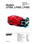
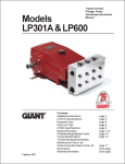
Triplex Ceramic Plunger Pump Operating Instructions/ Manual Models GP5132, GP5136 & GP5145 Contents: Installation Instructions: page 2 Pump Specifications: pages 3-5 Parts List/Exploded View: pages 6-7 Kits/Torque Specs: page 8 Trouble Shooting: page 9 Repair Instructions: page 10-11 Dimensions: back page Warranty Informationback page INSTALLATION INSTRUCTIONS Installation of the Giant Industries, Inc., pump is not a complicated procedure, but there are some basic steps common to all pumps. The following information is to be considered as a general outline for installation. If you have unique requirements, please contact Giant Industries, Inc. or your local distributor for assistance. 1. The pump should be installed flat on a base to a maximum of a 15 degree angle of inclination to ensure optimum lubrication. 2. The inlet to the pump should be sized for the flow rate of the pump with no unnecessary restrictions that can cause cavitation. Teflon tape should be used to seal all joints. If pumps are to be operated at temperatures in excess of 1400 F, it is important to insure a positive head to the pump to prevent cavitation. 5. Crankshaft rotation on Giant Industries, Inc. pumps should be made in the direction designated by the arrows on the pump crankcase. Reverse rotation may be safely achieved by following a few guidelines available upon request from Giant Industries, Inc. Required horsepower for system operation can be obtained from the charts on pages 3-5. 6. Before beginning operation of your pumping system, remember: Check that the crankcase and seal areas have been properly lubricated per recommended schedules. Do not run the pump dry for extended periods of time. Cavitation will result in severe damage. Always remember to check that all plumbing valves are open and that pumped media can flow freely to the inlet of the pump. 3. The discharge plumbing from the pump should be properly sized to the flow rate to prevent line pressure loss to the work area. It is essential to provide a safety bypass valve between the pump and the work area to protect the pump from pressure spikes in the event of a blockage or the use of a shut-off gun. 4. Use of a dampener is necessary to minimize pulsation at drive elements, plumbing, connections, and other system areas. The use of a dampener with Giant Industries, Inc. pumps is optional, although recommended by Giant Industries, Inc. to further reduce system pulsation. Dampeners can also reduce the severity of pressure spikes that occur in systems using a shut-off gun. A dampener must be positioned downstream from the unloader. Finally, remember that high pressure operation in a pump system has many advantages. But, if it is used carelessly and without regard to its potential hazard, it can cause serious injury. 2. Pump operation must not exceed rated pressure, volume, or RPM. A pressure relief device must be installed in the discharge of the system. IMPORTANT OPERATING CONDITIONS Failure to comply with any of these conditions invalidates the warranty 1. Prior to initial operation, add oil to crankcase so that oil level is between the two lines on the oil dipstick. DO NOT OVERFILL. SAE 80 or SAE 90 Industrial Gear oil may be used. Crankcase oil should be changed after the first 50 hours of operation, then at regular intervals of 500 hours or less depending on operating conditions. 3. Acids, alkalines, or abrasive fluids cannot be pumped unless approval in writing is obtained before operation from Giant Industries, Inc. 4. Run the pump dry approximately 10 seconds to drain the water before exposure to freezing temperatures. NOTE: Contact Giant Industries for Service School Information. Phone: (419)-531-4600 2 Specifications Model GP5132 Volume ................................................................................................... Up to 29 GPM Discharge Pressure ................................................................................ Up to 3000 PSI Speed ..................................................................................................... Up to 1000 RPM Inlet Pressure ......................................................................................... Up to 145 PSI Plunger Diameter.................................................................................... 32 mm Plunger Stroke ........................................................................................ 46mm Crankshaft Diameter .............................................................................. 35mm x 10mm key Crankshaft Mounting .............................................................................. Either side Shaft Rotation ............................................................................. Top of pulley towards manifold Temperature of Pumped Fluids ............................................................... Up to 140 oF Inlet Ports ............................................................................................... (3) 1-1/2" BSP Discharge Ports ...................................................................................... (2) 1" BSP Weight .................................................................................................... 179 lbs. Crankcase Oil Capacity .......................................................................... 1.2 Gal. Fluid End Material................................................................................... Cast Iron Consult the factory for special requirements that must be met if the pump is to operate beyond one or more of the limits specified above. GP5132 HORSEPOWER REQUIREMENTS RPM GPM 1OOO PSI 15OO PSI 2OOO PSI 25OO PSI 3000 PSI 600 17.4 12 18 24 30 36 700 20.3 14 21 28 35 42 900 26.1 18 27 36 45 54 1000 29 20 30 40 50 60 HORSEPOWER RATINGS: The rating shown are the power requirements for the pump. Gas engine power outputs must be approximately twice the pump power requirements shown above. We recommend a 1.15 service factor be specified when selecting an electric motor as the power source. To compute specific pump horsepower requirements, use the following formula: HP = (GPM X PSI) / 1450 SPECIAL NOTE: FOR CONTINUAL OPERATION, THE SPEED OF THE PUMP MUST BE LIMITED TO 700 RPM, AND THE MAXIMUM PRESSURE OF THE PUMP MUST BE REDUCED BY 10%. 3 Specifications Model GP5136 Volume ................................................................................................... Up to 35 GPM Discharge Pressure ................................................................................ Up to 2200 PSI Speed ..................................................................................................... Up to 945 RPM Inlet Pressure ......................................................................................... Up to 145 PSI Plunger Diameter.................................................................................... 36mm Plunger Stroke ........................................................................................ 46mm Crankshaft Diameter .............................................................................. 35mm x 10mm key Crankshaft Mounting .............................................................................. Either side Shaft Rotation ............................................................................. Top of pulley towards manifold Temperature of Pumped Fluids ............................................................... Up to 140 oF Inlet Ports ............................................................................................... (3) 1-1/2" BSP Discharge Ports ...................................................................................... (2) 1" BSP Weight .................................................................................................... 179 lbs. Crankcase Oil Capacity .......................................................................... 1.2 Gal. Fluid End Material................................................................................... Cast Iron Consult the factory for special requirements that must be met if the pump is to operate beyond one or more of the limits specified above. GP5136 HORSEPOWER REQUIREMENTS RPM GPM 1OOO PSI 15OO PSI 1800 PSI 2000 PSI 2200 PSI 700 26 18 27 33 36.3 39.4 750 28 19 29 35 39 42.5 800 30 21 31 37 41 45.5 850 32 22 33 40 44 48.6 945 35 24.1 36.2 43.4 48.2 53.1 HORSEPOWER RATINGS: The rating shown are the power requirements for the pump. Gas engine power outputs must be approximately twice the pump power requirements shown above. We recommend a 1.15 service factor be specified when selecting an electric motor as the power source. To compute specific pump horsepower requirements, use the following formula: HP = (GPM X PSI) / 1450 SPECIAL NOTE: FOR CONTINUAL OPERATION, THE SPEED 700 RPM, AND THE MAXIMUM PRESSURE OF THE PUMP MUST BE REDUCED BY 10%. OF THE PUMP MUST BE LIMITED TO 4 Specifications Model GP5145 Volume ................................................................................................... Up to 43.3 GPM Discharge Pressure ................................................................................ Up to 1500 PSI Speed ..................................................................................................... Up to 750 RPM Inlet Pressure ......................................................................................... Up to 145 PSI Plunger Diameter.................................................................................... 45mm Plunger Stroke ........................................................................................ 46mm Crankshaft Diameter .............................................................................. 35mm x 10mm key Crankshaft Mounting .............................................................................. Either side Shaft Rotation ............................................................................. Top of pulley towards manifold Temperature of Pumped Fluids ............................................................... Up to 140 oF Inlet Ports ............................................................................................... (3) 1-1/2" BSP Discharge Ports ...................................................................................... (2) 1" BSP Weight .................................................................................................... 179 lbs. Crankcase Oil Capacity .......................................................................... 1.2 Gal. Fluid End Material................................................................................... Cast Iron Consult the factory for special requirements that must be met if the pump is to operate beyond one or more of the limits specified above. HORSEPOWER RATINGS: The rating shown are the power requirements for the pump. Gas engine power outputs must be approximately twice the pump power requirements shown above. GP5145 HORSEPOWER REQUIREMENTS RPM GPM 1OOO PSI 1100 PSI 1300 PSI 1500 PSI 550 31.9 22 24.2 28.6 33 600 34.9 24.1 26.5 31.3 36.1 650 37.8 26 28.7 33.9 39.1 700 40.6 28 30.8 36.4 42 750 43.3 29.9 32.8 38.8 44.8 We recommend a 1.15 service factor be specified when selecting an electric motor as the power source. To compute specific pump horsepower requirements, use the following formula: HP = (GPM X PSI) / 1450 SPECIAL NOTE: FOR CONTINUAL OPERATION, THE SPEED OF THE PUMP MUST BE LIMITED TO 700 RPM, AND THE MAXIMUM PRESSURE OF THE PUMP MUST BE REDUCED BY 10%. 5 GP5100 Series PARTS LIST ITEM 1 2 3 4 5 8 9 10 11 12 13 14 15 16 17 18 20 20A 21 22 23 24 25 28 29A 29B 29B 29B 29C 29D 30 31 35 35 35 35A 35A 35B 36 36 36 37 37A PART 13266 13000 07186 13267 13268 07105 01009 13270 13134 07703 13269 13271 13272 08182 13358 13134 13206 13207 13273 13274 13275 13276 13279 13281 07125 13022 07130 13283 07131 07755 13282 13284 13359 13288 13287 13289 13286 08183 13360 13291 13290 13361 07700 DESCRIPTION Crankcase Oil Filler Plug Assembly Oil Sight Glass Assy. Crankcase Cover O-Ring Oil Dip Stick O-Ring, Dip Stick Inner Hexagon Screw Spring Washer Drain Plug G 3/4" Gasket, Drain Plug Bearing Cover Radial Shaft Seal O-Ring Hexagon Screw Spring Washer Taper Roller Bearing Fitting Disc (Shim) Shaft Protector Crankshaft Fitting Key Connecting Rod Assy. Crosshead Assy. Crosshead Pin Centering Sleeve Plunger Pipe (GP5132) Plunger Pipe (GP5136) Plunger Pipe (GP5145) Tension Screw Oil Scraper Copper Ring Radial Shaft Seal Seal Sleeve (GP5132) Seal Sleeve (GP5136) Seal Sleeve (GP5145) O-Ring (GP5136) O-Ring (GP5145) O-Ring Grooved Ring (GP5132) Grooved Ring (GP5136) Grooved Ring (GP5145) Seal Case (GP5132) O-Ring (GP5132) QTY. 1 1 1 1 1 1 1 4 4 1 1 2 2 2 8 8 2 5 1 1 1 3 3 3 3 3 3 3 3 3 3 3 3 3 3 3 3 3 3 3 3 3 3 6 ITEM 37B 39 39 39 40 40 40 41 PART 07653 13026 07142 13293 13027 07144 13294 13028 41 07146 41 13296 42 42 42 42A 43 46 46A 46B 46C 46D 46E 46F 46G 47 47A 47B 47C 47D 47E 47F 48 48A 48B 48C 49 52 53 54 55 07173 07147 13297 13298 13300 13302 12055 08059 13304 13306 13307 13308 13309 13311 13312 07700 13314 13306 13307 13308 13316 07008 07740 07232 13362 13363 13358 13321 13322 DESCRIPTION QTY. O-Ring (GP5132) 3 Pressure Ring (GP5132) 3 Pressure Ring (GP5136) 3 Pressure Ring (GP5145) 3 V-Sleeve (GP5132) 6 V-Sleeve (GP5136) 6 V-Sleeve (GP5145) 6 Sleeve Support Ring (GP5132) 3 Sleeve Support Ring (GP5136) 3 Sleeve Support Ring (GP5145) 3 Tension Spring (GP5132) 3 Tension Spring (GP5136) 3 Tension Spring (GP5145) 3 Spring Guide (GP5136 only) 3 Valve Casing 1 Suction Valve Assy. 3 O-Ring 1* O-Ring 1* Suction Valve Seat 1* Valve Plate 1* Valve Spring 1* Spring Tension Cap 1* Spacer Pipe 1* Discharge Valve Assy. 3 O-Ring 1* O-Ring 1* Discharge Valve Seat 1* Valve Plate 1* Valve Spring 1* Spring Tension Cap 1* Plug 3 Inner Hexagon Screw 12 O-Ring 3 Pressure Ring 3 Inner Hexagon Screw 8 Disc for Crankshaft 1 Hexagon Screw 1 Plug G 1" 1 Plug G 1-1/2" 2 Exploded View - GP5100 Series 7 GP5100 SERIES REPAIR KITS Plunger Packing Kits Valve Assembly Kits GP5132 Inlet Valve Kit, GP5100 Series, #09231 Qty. 3 3 6 #09290 Part # 08183 13360 13027 GP5136 Qty. 3 3 3 6 Qty. 1 1 1 1 1 #09229 Part # 13289 08183 13291 07144 GP5145 Qty. 3 3 3 6 Description O-Ring Grooved Ring V-Sleeve Description O-Ring O-Ring Grooved Ring V-Sleeve Description O-Ring O-Ring Valve Seat Valve Plate Valve Spring Discharge Valve Kit, GP5100 Series, # 09232 Qty. 1 1 1 1 1 #09228 Part # 13286 08183 13290 13294 Part # 12055 08059 13304 13306 13307 Description O-Ring O-Ring Grooved Ring V-Sleeve Part # 13312 07700 13314 13306 13307 Description O-Ring O-Ring Valve Seat Valve Plate Valve Spring Oil Seal Kit GP5100 Series, #09230 Qty. 3 Part # 13284 Description Oil Seal GP5100 SERIES TORQUE SPECIFICATIONS Position Item# 24 29C 48A 49 13276 07131 07008 13362 Description Torque Amount (ft.-lbs) Connecting Rod Assy. Tension Screw, Plunger Inner Hexagon Screw, Plug Inner Hexagon Screw, Valve Casing 8 26 26 35 85 PUMP SYSTEM MALFUNCTION MALFUNCTION CAUSE REMEDY The Pressure and/ or the Delivery Drops Worn packing seals Broken valve spring Belt slippage Worn or Damaged nozzle Fouled discharge valve Fouled inlet strainer Worn or Damaged hose Worn or Plugged relief valve on pump Cavitation pump for restrictions Unloader Replace packing seals Replace spring Tighten or Replace belt Replace nozzle Clean valve assembly Clean strainer Repair/Replace hose Clean, Reset, and Replace worn parts Check suction lines on inlet of Water in crankcase High humidity Worn seals Reduce oil change interval Replace seals Noisy Operation Worn bearings Replace bearings, Refill crankcase oilwith recommended lubricant Check inlet lines for restrictions and/or proper sizing Cavitation Rough/Pulsating Operation with Pressure Drop Worn packing Inlet restriction Check for proper operation Replace packing Check system for stoppage, air leaks, correctly sized inlet plumbing to pump Recharge/Replace accumulator Check for proper operation Check inlet lines for restrictions Accumulator pressure Unloader Cavitation and/or proper size Pump Pressure as at gun Rated, Pressure Restricted discharge plumbing Re-size discharge plumbing to Drop flow rate of pump Excessive Leakage Worn plungers Worn packing/seals Excessive vacuum Cracked plungers Inlet pressure too high Replace plungers Adjust or Replace packing seals Reduce suction vacuum Replace plungers Reduce inlet pressure High Crankcase Temperature Wrong Grade of oil Improper amount of oil in crankcase Giant oil is recommended Adjust oil level to proper amount 9 REPAIR INSTRUCTIONS Note: Always take time to lubricate all metal and nonmetal parts with a light film of oil before reassembly. This step will ensure proper fit, at the same time protecting the pump's nonmetal parts (i.e., the elastomers) from cutting and scoring. To Check Valves 1. Screw-out inner hexagon screws (48A) with an allen wrench. Remove discharge plugs (48) with a screw driver. Check O-Rings (48B) on discharge plugs and replace as necessary. 2. Pull out Pressure Ring (48C). Remove the Spring Tension Cap (47F) from the discharge Valve Plate (47D) lying underneath by screwing in the 10mm screw. Take out the Valve Spring (47E) and Valve Plate (47D). Pull out the Discharge Valve Seat (47C) by means of slide hammer. Check sealing areas of the Valve Plate (47D) and the Valve Seat (47C) for damage and replace worn parts. Check O-Rings (47A and 47B) and replace as necessary. 3. Screw Spacer Pipe (46G) out of the Spring Tension Cap (46F) located in the suction valve lying underneath. Remove the Suction Valve Assembly (46) by screwing in a 10mm screw. Check O-Rings (46A and 46B) and replace as necessary. If the Suction Valve Seat (46C) remains in the Valve Casing (43), remove it with a slide hammer. Check the sealing areas of the Suction Valve Plate (46D) and the Suction Valve Seat (46C) for damage and replace worn parts. 4. After reassembling the above items, tighten the Inner Hexagon Screws (48A) to 35 ft.-lbs. To Check Seals and Plunger Pipes 1. Loosen the eight Inner Hexagon Screws (49) and pull of the Valve Casing (43) to the front. Pull Seal Sleeves (35) out of the guides in the crankcase and over the plunger pipes (29B). Remove Sleeve Support Ring (41), Sleeves (40) and Grooved Rings (36). Replace worn parts as necessary. 2. If a Plunger Pipe (29B) is worn out, loosen the Tension Screw (29C) and pull off the Plunger Pipe to the front. Clean the contact surfaces of the Crosshead Assembly (25) thoroughly. Place the new plunger pipe carefully through oiled seals back into the seal case. Check O-Rings (35A and 35B) on the Seal Sleeves (35) and replace as necessary. 3. Push the Seal Sleeves (35) together with the Plunger Pipe (29B) back into the crankcase guide. Turn the crankshaft (22) carefully until the Crosshead Assembly (25) comes up against the Plunger Pipe. Put a new Oil Scraper (29D) onto the Tension Screw (29C). Cover the thread of the Tension Screw and the Oil Scraper and apply a liquid adhesive such as Lock-Tite. Tighten Tension Screw to 26 ft.-lbs.. Important!! Do not get any adhesive between the Plunger Pipe (29B) and the Centering Sleeve (29A). The Plunger Pipe should not be strained by excessive force on the Tension Screw (29C) or through damage to the front surface of the Plunger. If these conditions are ignored, the Plunger Pipe will probably break. 4. Tighten the Inner Hexagon Screws (49) to the Valve Casing (43) to 85 ft.-lbs. 10 To Disassemble Gear End 1. Loosen Inner Hexagon Screws (49) for the Valve Casing (43) with an allen wrench. Carefully remove Valve Casing from the Crankcase (1). 2. Loosen Inner Hexagon Screws (10) for the Crankcase Cover (4) with an allen wrench and remove Crankcase Cover. 3. Loosen Hexagon Screws (17) for the Bearing Covers (14) with a wrench and remove Bearing Cover. 4. Drain oil from the Crankcase (1) by removing Drain Plug (12) with a 3/4" wrench. 5. Loosen Connecting Rod Screws (24) with an allen wrench. Push the stems of the connecting rods as far as possible into the crosshead guides. Carefully push out the Radial Shaft Seals(31). Important!! Connecting Rods (24) are marked for identification. Do not twist Connecting Rod halves. Connecting Rods must be reinstalled in the same position on the Crankshaft (22) journals. 6. While slightly turning the Crankshaft (22), hit it out carefully to one side with a rubber hammer. Important!! Do not bend Connecting Rod (24) shank. 7. Check the surfaces of the Crankshaft (22), Connecting Rods (24), Crosshead Assemblies (25) as well as the Radial Shaft Seals (15 and 31) and Taper Roller Bearings (20). To Reassemble Gear End 1. Using a soft tool, such as brass or wooden dowel, press in the outer bearing ring until it lines up with the outer edge of the bearing hole. Assemble the Bearing Cover (14) together with the Shaft Seal (15) and O-Ring (16). 2. Fit the Crankshaft (22) with pressed-on bearing parts through the bearing hole on the opposite side. Press in outer bearing ring and push it inwards with the Bearing Cover (14) while keeping the Crankshaft in the vertical position and turning it slowly so that the taper rollers of the bearings touch the edge of the outer bearing ring. 3. Adjust axial bearing clearance with Fitting Discs (20A) which are 0.1mm each. The Crankshaft (22) should turn easily with very little clearance. Tighten Inner Hexagon Screws on the Connecting Rods (24) to 26 ft.-lbs.. Important!! There should be enough clearance for the Connecting Rods (24) to move sideways a little on the journals. 11 DIMENSIONS 10mm X 63mm Key OUTLET 18.9" 4.61" 13.9" 2.87" 2.68" 9.06" 4.33" 3.06" 7.68" 9.69" 8.27" 10.2" 19.1" INLET 2.17" 20.6" GIANT INDUSTRIES LIMITED WARRANTY Giant Industries, Inc. pumps and accessories are warranted by the manufacturer to be free from defects in workmanship and material as follows: 1. For portable pressure washers and car wash applications, the discharge manifolds will never fail, period. If they ever fail, we will replace them free of charge. Our other pump parts, used in portable pressure washers and in car wash applications, are warranted for five years from the date of shipment for all pumps used in NON-SALINE, clean water applications. 2. One (1) year from the date of shipment for all other Giant industrial and consumer pumps. 3. Six (6) months from the date of shipment for all rebuilt pumps. 4. Ninety (90) days from the date of shipment for all Giant accessories. This warranty is limited to repair or replacement of pumps and accessories of which the manufacturer’s evaluation shows were defective at the time of shipment by the manufacturer. The following items are NOT covered or will void the warranty: 1. Defects caused by negligence or fault of the buyer or third party. 2. Normal wear and tear to standard wear parts. 3. Use of repair parts other than those manufactured or authorized by Giant. 4. Improper use of the product as a component part. 5. Changes or modifications made by the customer or third party. 6. The operation of pumps and or accessories exceeding the specifications set forth in the Operations Manuals provided by Giant Industries, Inc. Liability under this warranty is on all non-wear parts and limited to the replacement or repair of those products returned freight prepaid to Giant Industries which are deemed to be defective due to workmanship or failure of material. A Returned Goods Authorization (R.G.A.) number and completed warranty evaluation form is required prior to the return to Giant Industries of all products under warranty consideration. Call (419)-531-4600 or fax (419)-531-6836 to obtain an R.G.A. number. Repair or replacement of defective products as provided is the sole and exclusive remedy provided hereunder and the MANUFACTURER SHALL NOT BE LIABLE FOR FURTHER LOSS, DAMAGES, OR EXPENSES, INCLUDING INCIDENTAL AND CONSEQUENTIAL DAMAGES DIRECTLY OR INDIRECTLY ARISING FROM THE SALE OR USE OF THIS PRODUCT. THE LIMITED WARRANTY SET FORTH HEREIN IS IN LIEU OF ALL OTHER WARRANTIES OR REPRESENTATION, EXPRESS OR IMPLIED, INCLUDING WITHOUT LIMITATION ANY WARRANTIES OR MERCHANTABILITY OR FITNESS FOR A PARTICULAR PURPOSE AND ALL SUCH WARRANTIES ARE HEREBY DISCLAIMED AND EXCLUDED BY THE MANUFACTURER. GIANT INDUSTRIES, INC., 900 N. Westwood Ave., P.O. Box 3187 Toledo, Ohio 43607, Phone (419) 531-4600, FAX (419) 531-6836, www.giantpumps.com 3/98 GP5100.PM6 Copyright 1996 Giant Industries, Inc.