1
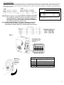
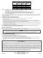
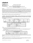
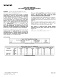
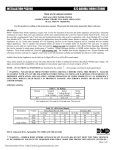
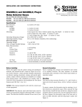
GEC3-12, GES3-12
& GEH12 SERIES
UL 1971 COMPLIANT
CAN/ULC S526-M87 Compliant
VISIBLE AND/OR AUDIBLE SIGNALING APPLIANCES
I. INTRODUCTION
The Gentex Model GEC3-12/GES3-12/GEH12, horn/strobe, strobe or horn, is a high quality audible and/or visible signaling appliance. The high intensity strobe
utilizes a Xenon flash tube that generates a high-intensity flash visible from all angles. This appliance is intended to provide a visible, audible or audible/visible,
depending on the model, notification signal for the purpose of life safety and property protection. The GEC3-12 and GES3-12 are provided with a slider switch
which allows for candela selection at the installation site. The intensities which can be selected are 15Cd, 30Cd, 60Cd or 75Cd. This appliance is ideal for any
occupancy that requires notification appliances per the applicable building or fire code or wherever dependable alarms are required. The strobe is listed in
compliance with UL 1971, Signaling Appliances for the Hearing Impaired and CAN/UL S526-M87 Visible Signal Devices for Fire Alarm Systems.
II. LOCATION
This appliance is intended for use in Fire Alarm Systems and is to be installed in accordance with this manual, the recommendation of the local authorities
having jurisdiction, and other NFPA documents that provide standards on notification appliances for protective signaling systems. The GEC3-12/GES3-12 is
intended for indoor installations only. This appliance is not weatherproof for outdoor or drip proof applications.
Wall mounted strobe and horn/strobe appliances shall have their entire lens at heights above the finished floor of not less than 80 in. (2m) and not greater than
96 in. (2.4m)**. Spacing shall be in accordance with Table A. If a room configuration is not square, the room size that will entirely encompass the room or
subdivide the room into multiple squares shall be used.
Wall mounted horn only appliances shall have their tops above the finished floors at heights of not less than 90in. (2.30m) and below the finished ceilings at
heights of not less than 6 in. (152mm). Different mounting heights shall be permitted by the AHJ provided the sound pressure level requirements of NFPA 72 are
met.
Table A
Maximum Room Size
Meters
Feet
6.10 x 6.10
8.53 x 8.53
9.14 x 9.14
12.2 x 12.2
13.7 x 13.7
15.2 x 15.2
16.5 x 16.5
18.3 x 18.3
21.3 x 21.3
24.4 x 24.4
27.4 x 27.4
30.5 x 30.5
33.5 x 33.5
36.6 x 36.6
39.6 x 39.6
20 x 20
28 x 28
30 x 30
40 x 40
45 x 45
50 x 50
54 x 54
60 x 60
70 x 70
80 x 80
90 x 90
100 x 100
110 x 110
120 x 120
130 x 130
Minimum Required Light Output (Effective Intensity, Cd)
Two Lights per
Four Lights per
One Light
Room (Located on
Room (One Light
per Room
Opposite Walls)
per Wall)
15
30
34
60
75
94
110
135
184
240
304
375
455
540
635
NA
Unknown
15
30
Unknown
6
Unknown
95
95
135
185
240
240
305
375
NA
Unknown
NA
15
Unknown
30
Unknown
30
60
60
95
95
135
135
185
NA = Not allowable.
**Effective Intensity Requirements
for Sleeping Areas
Visible Notification Appliance
Distance from Ceiling to Top of Lens
Intensity
greater than or equal to 24"
less than 24"
110cd
177cd
III. MOUNTING, ROUGH-IN BOX AND RUN WIRING
This unit is designed for mounting to most single gang boxes, 4" square outlet boxes, 2-gang masonry boxes or non-metallic 2-gang switch boxes.
Conduit entrance to boxes should be selected to insure sufficient wiring clearance.
1. Run a minimum 18 gauge insulated 2 or more conductor cable.
2. Mount a box for each remote signaling appliance. Screw bracket onto box. Insert signal into bracket and slide to the right firmly into the terminal block
receptacle. Place housing over mounted assembly and screw together with single screw at the bottom of the signal. Cover screw with plastic tab.
Attention: Wiring should be connected to mounting bracket prior to mounting signal. Incoming positive power lead must be broken and each
lead is to be inserted into each of the top two terminals. If two power runs are made to the signal, one for the strobe and one for the horn, only
one of the runs must have its positive lead broken and placed under the two separate top terminals. A barrier is provided to prevent both leads
from being placed under the same terminal.
1
(GEC3-12 & GES3-12 ONLY)
CheckmateTM Voltage Verification
Access Holes:
It is often necessary to confirm the voltage
drop along a line of devices. The access
holes are provided in the back of the terminal
block to allow the voltage to be measured
directly without removing the device. Typically
this would be done at the end of the line to
confirm design criteria. Most measurements
will be taken using the S+ and S- locations
although access is provided to other locations.
NOTE: Care should be taken to not short
the test probes.
CAUTION: A jumper card is provided to test for correct wiring in the supervisory mode only. DO NOT pass alarm current through the jumper.
NOTE: All strobes are designed to flash as specified with continuous applied voltage. This appliance is not recommended for use on coded or pulsing
signaling circuits. However, use of the AVSM control module is permitted to synchronize the strobe and/or mute the horn.
IV. WIRING
Wiring for independent synchronized strobes and horn.
Using this method you may:
· Use only two wires to synchronize the temporal horn and strobe with the ability to mute the horn (place switches 1 and 2 up on the GEC3-12).
· Mute the horn only when the temporal horn option has been selected.
Wiring for synchronized parallel (unison) horn/strobe operation.
Using this method you may:
· Use only two wires to synchronize the temporal horn and strobe without the ability to mute the horn (place switches 1 and 2 up on the GEC3-12).
· Choose either temporal or continuous horn with the temporal horn synchronized.
· Also wire the control module (AVSM) to only the strobe input power terminals, set the horn to continuous mode and power it from a coded source.
NOTE: For this option, switches 1 and 2 on the GEC3-12 (Fig.1) must be down to isolate power to the audible and visible portion of the circuit.
2
Conventional Method:
You may connect both the strobe and the horn directly from a source of rated power without the use of a control module. However, the horns and strobe
lights will NOT be synchronized. Place switches 1 and 2 up on the GEC3-12 (Fig.1) to power both the audible and visible from a single pair of power
wires. If you wish to power the horn and strobe from independent sources of power, place switches 1 and 2 down on the GEC3-12 and connect power to
the appropriate terminals.
MAX. WIRE
DISTANCE =
(IN FEET)
CAUTION: When using only a single power source to energize the strobe and
horn (switches 1 and 2 up), the in/out wiring must be under the S+
and S- terminals only. Failure to do so may result in damage to
your signal. For the horn only (GEH12) and strobe only (GES3-12),
only the top three terminals are to be used.
NOTE: INSTALLATION IN CANADA - All Canadian installations should be in
accordance with the Canadian Standard for the Installation of Fire
Alarm Systems- CAN/ULC S524-01 the Canadian Electrical Code, Part 1.
(PANEL VOLTAGE-APPLIANCE MIN. VOLT) X WIRE CONDUCTIVITY
TOTAL CURRENT DRAW
WIRE
CONDUCTIVITY
18AWG
60
16AWG
95
14AWG
153
12AWG
244
Includes wire to and from appliance. CAUTION: Applies only to
regulated supplies. Assumes all appliances are at the end of
wire run (worst case).
Fig. 1
Grip both
sides of bezel
and pull in a
downward
and outward
motion.
Strobe Current Ratings
Regulated 12V Maximum
Candela
DC(mA) Operating Current
15
163
30
212
60
331
75
436
3
HORN RATINGS OVER INPUT VOLTAGE RANGE OF 8-17.5V
Horn Mode
Regulated
Regulated
Regulated Minimum
Minimum
Minimum
DC(mA) @
dBA @ 10Ft.
dBA @ 10Ft.
HIGH Setting
Per UL464 (HIGH) Per UL464 (LOW)
Temp 3 2400Hz
76
69*
29
Temp 3 Mechanical
75
68*
26
Temp 3 Chime
62*
60*
13
Continuous 2400Hz
79
74*
29
Continuous Mechanical
78
72*
26
Continuous Chime
63*
61*
13
Whoop
78
71*
55
NOTE:
- DC Voltage Range Limits: 8-17.5V. This product was only tested to the stated voltage range(s); do not apply 80% and 110% of this range for
system operation.
- The three pulse temporal pattern is to be used for evacuation use only.
- The sound output for the temporal 3 tone is rated lower since the time the horn is off is averaged into the sound out
put rating. While the horn is producing a tone in the temporal 3 mode its sound pressure is the same as the
continuous mode. Units have been tested to 0°C, 49°C and 93% humidity and are rated 20-30vdc/vFWR -20%,
+10% per CAN/ULC S526-M87.
*Operating the horn in this mode at this voltage will result in not meeting the minimum UL reverberant sound level required for public mode fire protection
service. These settings are acceptable only for private mode fire alarm signaling use. Use the high dBA setting for public mode applications (the chime
tone is always private mode).
V. CHECKOUT AND TROUBLESHOOTING
1. Supply power to the system control panel. The auxiliary signaling appliances in the system should not be activated.
2. If the signal is activated:
·
Check all smoke and fire detectors in the system to make sure they have not been activated.
·
Check all wiring connections to make sure the signal detection circuits are not reversed or shorted together. Check wire color codes and traces.
·
Verify that the jumpers and switches are properly set on both the control module and signal appliance. If the jumper on the AVSM is removed, the horns
will not produce any sound unless there is an input to the H+ and H- terminals on the control module.
3. To test the signal appliances, trip the auxiliary panel or activate the alarm circuit at the main control panel or activate one of the fire detection units in the
system. All auxiliary signals should be activated.
4. An operational test on this product should be conducted in accordance with National Standards or at a minimum annually and more often if dictated by
local and state codes or authorities having jurisdiction.
NOTE: These testing procedures and troubleshooting instructions are generalized. Please refer to the system control panel operating
instructions for proper operation of the panel and fire detection system.
SIGNALING APPLIANCE LIMITATION:
Your horn and horn/strobe meet or exceed the current audibility requirements of Underwriters Laboratories. However, if the appliance is located outside a
bedroom it may not wake up a sound sleeper, especially if the room door is closed or only partially open.
WARNING
THIS APPLIANCE WILL NOT OPERATE WITHOUT ELECTRICAL POWER. AS FIRES FREQUENTLY CAUSE POWER INTERRUPTIONS,
GENTEX SUGGESTS YOU DISCUSS FURTHER SAFEGUARDS WITH YOUR LOCAL FIRE PROTECTION SPECIALIST.
VI. TO RETURN AN APPLIANCE:
Should you experience problems with your appliance, proceed as follows:
1. Turn off electrical power to the auxiliary alarm circuit.
2. Remove the bezel, then mounting screw (under name tab) and slide signal off from bracket
3. Replace unit that was removed to restore wiring supervision and to eliminate system trouble alert.
4. Carefully pack the defective unit (the manufacturer cannot be responsible for consequential damage due to shipping or mis-handling). Include your
return address and complete details as to the nature of the difficulties being experienced and date of installation.
5. Return to: Gentex Corporation, 10985 Chicago Dr., Zeeland MI 49464. Prior to returning, call the Gentex field service dept. @ 1-800-436-8391 for a
RMA number.
LIMITED WARRANTY
For a period of 36 months from the date of purchase or a maximum of 42 months from the date of manufacture, Gentex warrants to you the original purchaser that your appliance will be free from defects
in workmanship, materials and construction under normal use and service. If a defect in workmanship, materials and construction should cause your appliance to become inoperative within the warranty period, Gentex will repair your appliance or furnish you with a new or rebuilt appliance without charge to you except for postage required to return the appliance to us. Gentex will not reimburse you for repairs or
replacement parts provided by other parties. Your repaired or replacement appliance will be returned to you free of charge and it will be covered under the warranty for the balance of the warranty period.
The warranty is void if our inspection of your appliance shows that the damage or failure was caused by abuse, misuse, abnormal usage, faulty installation, improper maintenance or repairs other than those
performed by us.
ANY WARRANTIES IMPLIED UNDER ANY STATE LAW INCLUDING IMPLIED WARRANTIES OF MERCHANTABILITY OR FITNESS FOR A PARTICULAR PURPOSE APPLY ONLY FOR THE WARRANTY PERIOD SPECIFIED ABOVE. PLEASE NOTE THAT SOME STATES DO NOT ALLOW LIMITATION ON HOW LONG AN IMPLIED WARRANTY LASTS. SO THE ABOVE LIMITATION MAY NOT
APPLY TO YOU. GENTEX WILL NOT BE LIABLE FOR ANY LOSS, DAMAGE, INCIDENTAL OR CONSEQUENTIAL DAMAGES OF ANY KIND ARISING IN CONNECTION WITH THE SALE, USE OR
REPAIR OF THIS APPLIANCE. THE MAXIMUM LIABILITY OF GENTEX SHALL NOT IN ANY CASE EXCEED THE PURCHASE PRICE PAID BY YOU FOR THE APPLIANCE. PLEASE NOTE THAT
SOME STATES DO NOT ALLOW THE EXCLUSION OR LIMITATION OF INCIDENTAL OR CONSEQUENTIAL DAMAGES, SO THE ABOVE LIMITATION OR EXCLUSION MAY NOT APPLY TO YOU.
If a defect in workmanship, materials or construction should cause your appliance to become inoperable within the warranty period, you must return the appliance to Gentex postage prepaid. You must prove
to the satisfaction of Gentex the date of purchase of your appliance. Warranty service may only be performed by Gentex personnel at Gentex's facilities in Zeeland, Michigan. You must also pack the appliance to minimize the risk of it being damaged in transit. You must also enclose a return address. Appliances returned for warranty service should be sent to: Gentex Corporation, 10985 Chicago Dr., Zeeland
MI 49464. If we receive an appliance in a damaged condition as the result of shipping, we will notify you and you must seek a claim with the shipper.
THIS WARRANTY GIVES YOU SPECIFIC LEGAL RIGHTS AND YOU MAY ALSO HAVE OTHER RIGHTS WHICH VARY FROM STATE TO STATE.
550-280-03
Gentex Corporation
10985 Chicago Dr., Zeeland MI 49464
Phone: 800-436-8391
10/01/02
4