1
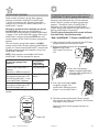
IntelliG ™ 1000
Model 3024
GARAGE DOOR OPENER
Includes INTELLICODE® 2 Remote Control. Safe-T-Beam® System must be installed to close door.
For use only with residential sectional or one piece overhead garage doors.
Homelink® and Car2U® compatible.
For Answers and Assistance:
1.800.354.3643
or visit www.geniepro.com
SAVE THIS MANUAL FOR FUTURE REFERENCE.
INSTALLER: LEAVE THIS MANUAL WITH HOMEOWNER.
Homelink® is a registered trademark of Johnson Controls Technology Company. Car2U® is a registered trademark of Lear Corporation. © 2010 The Genie Company PN# 37066500118, 01/27/2010
SAFETY INFORMATION
OVERVIEW OF POTENTIAL HAZARDS
READ THIS SAFETY INFORMATION
CONVENTIONS USED IN THESE INSTRUCTIONS
Garage doors are large, heavy objects that move with the help of springs under high tension and electric motors. Since moving
objects, springs under tension, and electric motors can cause injuries, your safety and the safety of others depend on you reading
the information in this manual. If you have questions or do not understand the information presented, call your nearest trained
door system technician or visit our website.
The following Safety Alert symbol and signal words are used throughout this manual to call attention to and identify different
levels of hazard and special instructions.
This is the safety alert symbol. This symbol alerts you to potential hazards that can kill or hurt you and others.
All safety messages will follow the safety alert symbol and the word "DANGER", "WARNING", or "CAUTION"
DANGER indicates an imminently hazardous situation which, if NOT avoided, will result in death or serious injury.
WARNING indicates a potentially hazardous situation which, if NOT avoided, could result in death or serious injury.
CAUTION indicates a potentially hazardous situation which, if NOT avoided, may result in injury or property damage.
The word NOTE is used to indicate important steps to be followed or important considerations.
IMPORTANT SAFETY INSTRUCTIONS
READ AND FOLLOW ALL INSTRUCTIONS
SAVE THESE INSTRUCTIONS
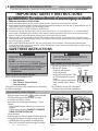
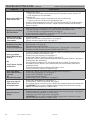
Potential Hazard
Effect
WARNING
Prevention
Keep people clear of opening while Door is moving.
Do NOT allow children to play with the Door Opener.
Could result in
Death or Serious Do NOT operate a Door that jams or one that has a broken
Injury
spring.
WARNING
Turn OFF power before removing opener cover.
When replacing cover, make sure wires are NOT pinched or
Could result in near moving parts.
Death or Serious
Injury
Opener must be fully grounded.
WARNING
Do NOT try to remove, install, repair or adjust springs or anything to which door spring parts are fastened, such as, wood
blocks, steel brackets, cables or other like items.
Could result in
Death or Serious Installations, repairs and adjustments must be done by a
Injury
trained door system technician using proper tools and instructions.
2
©2010 The Genie Company
01/27/2010
OPENER FEATURES
INTELLICODE® 2 Access Security System
A new generation superior encryption system that enhances the security of the door opener by continuously
changing the access code each time the remote is used. The door opener responds to each new code only once.
An access code copied from a working system and tried again will not control the door opener.
Wall Console
Operates door opener from inside garage. Indicator Light with: Open/Close, Vacation Lock, and Independent
Light Control buttons.
and Car2U® compatible. Refer to the programming instructions on page 9 and then
follow the HomeLink® or Car2U® instructions in your car owner’s manual.
SAFETY FEATURES
Safe-T-Beam® (STB) Non-Contact Reversing System
Puts an invisible beam across the door opening. The door stops and reverses to the full open position if anything
passes through the beam. LED indicator lights on the power head and on the STBs provide a self diagnostic code
if an operational problem exists.
Safe-T-Reverse® Contact Reversing System
Automatically stops and reverses a closing door within two seconds of contact with an object.
Automatic ForceGuard™ Control
Automatically sets the minimum force required to fully open and close the door for maximum safety.
Watch Dog™ Monitoring System
Monitors the Safe-T-Beam® system to ensure proper functionality and will automatically stop and reverse a
closing door if a problem is detected.
Automatic Lighting System
Two bulb lighting system supplies up to 200 Watts of light for safer evening exits and entries. Turns ON when
door is activated and automatically turns OFF 4 minutes later.
Manual Emergency Release
Manually releases door from door opener. Used during a power failure or other emergency to allow manual
opening and closing of door.
Ener-Genie™ Battery Back Up
Easily adjust the programming to reduce opening speed to a desired rate, optionally adjust limits and force, and
program new remotes.
SmartSet™ Electronic Programming
Easily adjust the programming to reduce opening speed to a desired rate, vary limits and force, and program new
remotes.
Integrated Motion Detection
(Not available on all models)
Select units have motion detection built into the power head. Lights automatically turn ON when motion is
detected for much safer movement through the garage. Lights will turn OFF after 4 minutes of no motion.
©2010
The Genie Company
01/27/2010
3
TABLE OF CONTENTS
Section ....................................................................................Page
Safety Information .................................................................................................... 2
Opener Features & Safety Features ................................................................... 3
Table of Contents ....................................................................................................... 4
Installation
Important Installation Instructions ........................................................5
1 Programming Limits & Force.............................................................6-7
2 Program IntelliCode® 2 Remote to Power Head ..........................8
Programming HomeLink®, Car2U®, IntelliCode® 1 remotes or wireless
keypads .................................................................................................................. 9
Reference
3 Typical Installed Illustrations ................................................................ 10-12
Typical Sectional Door Installation ............................................................10
Typical One Piece Door Installation ...........................................................11
Power Head & Rail Assembled View ...........................................................12
4 Overview of Power Head Controls .............................................................13
5 Overview of Remotes and Options...................................................... 14-16
Panic Button .......................................................................................................14
IntelliCode® Features ........................................................................................15
Previously Installed Openers ..........................................................................1
Lost or Stolen Remote - Clearing Memory ..................................................16
6 Maintenance & Troubleshooting ......................................................... 17-25
Important Safety Instructions........................................................................17
Routine Monthly Maintenance .....................................................................17
Door Balance (Spring Tension) ......................................................................17
Safe-T-Beam® System Check ..........................................................................17
Contact Reverse Test .........................................................................................18
Motion Detector - Overview ...........................................................................18
Reset - Open/Close Travel Limit .....................................................................18
Carriage Engage/Disengage ..........................................................................18
Wall Console - Overview ..................................................................................19
Change Light Bulbs ...........................................................................................19
Optional Dual Wall Console - Installation .................................................19
Chain or Belt Tension Adjustment ................................................................20
Remote Battery Replacement ........................................................................20
Wiring Diagram ................................................................................................21
Speed Adjustment ............................................................................................22
Force Adjustment ..............................................................................................23
Troubleshooting Guide - Operation ..................................................... 24-25
Troubleshooting Guide - Power Head LEDs ...............................................25
Warranty ......................................................................................................................26
PATENT STATEMENT
Patents Pending
4
©2010 The Genie Company
01/27/2010
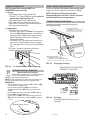
IMPORTANT INSTALLATION INSTRUCTIONS
WARNING:Toreducetheriskofsevereinjuryordeath:
1. READ AND FOLLOW ALL SAFETY, INSTALLATION
AND OPERATION INSTRUCTIONS. (If you have
questions or do not understand an instruction, call
The Genie Company.)
2. Install only on a properly balanced sectional or
one piece garage door. An improperly balanced
door could cause severe injury. Have a trained door
system technician make repairs or adjustments to
cables, spring assemblies, and other hardware before
installing the opener.
3. Remove all ropes and remove or make inoperative all
locks connected to the garage door before installing
opener.
4. Where possible, install the door opener 7 feet or
more above the floor. For products having an
emergency release, mount the emergency release 6
feet above the floor.
5. Do NOT connect the opener to source of power until
instructed to do so.
6. Locate the wall console:
• Within sight of the garage door,
• At minimum height of 5 feet so small children
are not able to reach it, and
• Away from all moving parts of the door.
7. Install the Entrapment WARNING Label next to the
wall console in a prominent location.
8. After installing the opener, the door must reverse
within 2 seconds when it contacts a 1-1/2 inch high
object (or a 2 x 4 board laid flat) on the floor.
INFRARED PROTECTION FUNCTION
1. When garage door is opening, its movement will not be influenced if the Safe-T-Beam® is
obstructed.
2. If the Safe-T-Beam® is obstructed before the garage door fully closes, the door will not close.
3. When the garage door is closing, if Safe-T-Beam® is interrupted by person or obstacle, the garage
door will stop its downward travel and reverse automatically to its fully opened position.
4. Remove Safe-T-Beam® obstruction.
5. If the Safe-T-Beam® System fails, loses power, or is installed improperly, press and hold the wall
console "open/close" button until the door reaches its fully closed position. If you release the
"open/close" button on the wall console during the closing movement the door will reverse
automatically to its fully opened position.
OPENER MUST BE INSTALLED WITH THE INCLUDED
WALL CONSOLE.
Safe-T-Beam® SAFETY REVERSE SYSTEM MUST BE
INSTALLED TO CLOSE DOOR.
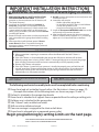
The following mechanical assembly tasks must be completed before continuing.
Power head and rail are bolted to each other (An illustration is shown on page 12)
(Example illustrations of the following items are shown on pages 10 and 11)
Rail end is attached to the garage door header
Power head is attached to a support frame suspended from the ceiling or ceiling joists
Rail door arm is attached to the garage door
Safe-T-Beam® units installed and wired
Wall console installed and wired
Door arm carriage is engaged to the chain or belt drive
Power head is plugged into an approved power outlet
Begin programming by setting Limits on the next page.
A PDF VERSION INSTALLATION POSTER IS AVAILABLE AT WWW.GENIECOMPANY.COM
OR CALL 1.800.354.3643 TO OBTAIN AN EMAIL PDF FILE
©2010
The Genie Company
01/27/2010
5
6
©2010 The Genie Company
01/27/2010
PRESS and
RELEASE
4
PROG
SET
PROGRAM
SET
PROGRAM
RAM
S ET
—
SEE round Blue
LED flashing
NOTE: If one or both LEDs come ON RED at this
time; Limits programming menu was not entered
properly. You must exit programming and restart.
To exit this mode:
A. Press and release
B. Pause
C. Press and release
D. Pause
E. Begin with Step 1 on this page. Restarting at
Step 1 will reset RED LEDs to BLUE.
Please note that there is a 30 second timeout
between each programming step.
A programming timeout during these steps has
occured when two RED flashing LEDs appear.
In the event of a timeout please restart at Step 1.
A) CLOSE DOOR TRAVEL LIMIT
RAM
S ET
—
SE
+
Watch door move
—
5 SECS
+
2
NOTE: You can start and stop door
movement using either
buttons until
door is in correct open or closed position.
GRAM
5 PRESS and HOLD
SEE BOTH
Blue LEDs
come ON
PROG
PRESS and HOLD
1
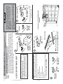
SETTING & TESTING LIMITS AND FORCE
The OPEN (UP) and CLOSE (DOWN) Door Limit positions are controlled by making
adjustments using the panel located on the bottom of the power head. Begin with
Step 1 and continue through Step 10. Door Force is set during the final Open/Close
cycle of these steps. The power head will automatically set door speed at slow if the
distance between limits is less than 6 feet.
from Installation Poster
1 PROGRAMMING LIMITS & FORCE (Continuing
if provided)
RAM
S ET
—
+
If RED LED comes ON - STOP and
exit programming.
SEE long Blue
LED come ON
PROG
PRESS and RELEASE
NO
T
OR
CM
U
O N
NH UC D
D
CE
Travel door to FULL CLOSED position
RELEASE
SEE round
Blue LED
come ON
RELEASE
3
• Make sure doorway is in view and clear of obstacles
and people to avoid injury or damage to property.
• DO NOT operate this unit from wall console before
LIMITS and FORCE are set. Severe damage to the
opener can occur.
• Bullet MUST be engaged to carriage BEFORE setting
limits. See Installation Poster (if provided) or refer to
pages 12 and 18.
WARNING
©2010
The Genie Company
01/27/2010
7
M
S ET
—
9
PRESS and
RELEASE
SET FORCE
SEE long Blue LED
flashing
RA
PROG
PRESS
6
RAM
S ET
+
Watch door move
—
PRESS and HOLD
OR
M
OW O
O
NOT
RC
D
AD
E
DOOR CLOSES
Force is set automatically with first full
OPEN/CLOSE door operation.
7
B) OPEN DOOR TRAVEL LIMIT
PRESS and
RELEASE
S ET
—
DOOR OPENS
Door Limits are set.
Both LEDs go OFF.
Continue with
FORCE setting.
RAM
PRESS and
RELEASE
PROG
8
Continue with programming remotes on the next
page of this manual.
10
NOTE: You can start and stop door
movement using either
buttons until
door is in correct open or closed position.
Travel door to FULL OPEN position
RELEASE
8
©2010 The Genie Company
01/27/2010
PROG
PRESS and
RELEASE
5
S ET
—
5 SECS
+
SEE both LEDs
flash Blue
RAM
PRESS and HOLD
SEE BOTH
Blue LEDs
come ON
1
RELEASE
PROG
RAM
PRESS and
RELEASE
S ET
—
+
SEE long Purple LED
come steady ON
The next press of the remote will operate door.
Repeat as necessary for other remotes.
PRESS and
RELEASE
4
A moving door can cause serious injury or death.
1. Keep people clear of opening while door is moving.
2. Do NOT allow children to play with opener, including
wall console, remote, or wireless keypad.
3. During programming, door opener could begin to run,
so stay away from moving door and its parts.
WARNING
FOR HELP-1.800.354.3643 OR WWW.GENIECOMPANY.COM
Basic power head programming is complete.
Your garage door opener is ready to use.
PRESS and
RELEASE
7
SEE long Purple
LED flashing
3
SEE both LEDs OFF
6
SEE round Blue
LED come ON
2
Bring remote(s) to power head location.
Begin with Step 1 and continue through Step 7 for each button to be programmed.
NOTE: The following instructions are for the remote(s) provided with this opener.
Remote(s) provided with this opener use a IntelliCode® 2 electronic access code
system. Refer to page 15 for additional information on IntelliCode® 1 and 2 remotes.
See page 9 for programming instructions using IntelliCode® 1 remotes.
2 PROGRAM INTELLICODE® 2 REMOTE TO POWER HEAD
©2010
The Genie Company
01/27/2010
9
S ET
—
5 SECS
+
2
SEE one
Blue LED
come ON
RELEASE
PROG
RAM
—
+
SEE both LEDs
flash Purple
PRESS a previously programmed Genie®
IntelliCode® 2 remote button on remote. If you
are unsure which remote you have see page 15.
Remote must be IntelliCode® 2 enabled.
4
other IntelliCode® 1 remotes.
8 Test. Repeat as necessary for any
the same button and RELEASE.
The next press of the remote will
operate door.
7 On the IntelliCode® 1 remote PRESS
6 SEE both LEDs flash Blue.
a button and RELEASE.
5 On the IntelliCode® 1 remote PRESS
Genie® IntelliCode® 1 remote
button
(3 seconds) on wireless keypad again
and see on power head both LEDs
come ON Blue.
Wait
30 seconds and test operation.
8
7 Press and hold
button
(3 seconds) on wireless keypad and
see on power head long LED come ON
Purple. (You may have to press
more than once.)
6 Press and hold
5 Enter your wireless keypad PIN.
Genie® IntelliCode® 1 wireless keypad
IntelliCode® 1 remote or wireless keypad programming
S ET
PRESS and
RELEASE
SEE long Purple
LED flashing
3
All optional programming is complete. Your garage door opener is ready to use.
instructions.
6 Test. Repeat as necessary for any other Car2U®
enabled vehicle.
5 For Car2U® enabled vehicles follow the Car2U®
Repeat as necessary for any other pre6 Test.
programmed Homelink® enabled vehicle.
5 PRESS the Homelink® button twice.
If your Homelink® has been previously programmed to an
Genie® opener begin with Step 5.
If your Homelink® has not yet been linked to a Genie®
opener then go to page 15 and change one remote button
from IntelliCode® 2 to IntelliCode® 1, then program that
button to the power head and repeat steps 1-4 then
continue with Homelink® steps 5-6.
Homelink® or Car2U® programming
SEE BOTH
Blue LEDs
come ON
RAM
PROG
1 PRESS and HOLD
PROGRAMMING POWER HEAD TO
Homelink®, Car2U®, or IntelliCode® 1 REMOTES and SERIES II WIRELESS KEYPADS
To complete any of these tasks you MUST have at least one Genie® IntelliCode® 2 remote button already
programmed to the power head.
Homelink® or Car2U®: You must also have your Homelink® or Car2U® enabled vehicle present and their
programming instructions to perform these programming steps.
Genie® remote: You must also have your Genie® IntelliCode® 1 remote present.
Genie® wireless keypad: You must also have your Genie® wireless keypad installed and a PIN already programmed into the keypad.
OPTIONAL
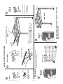
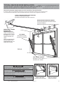
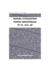
3 TYPICAL SECTIONAL DOOR INSTALLATION
FOR HELP-1.800.354.3643 OR WWW.GENIECOMPANY.COM
INSTALLATION TYPIQUE SUR UNE PORTE SECTIONELLE ..................................POUR OBTENIR DE L’AIDE-1.800.354.3643
INSTALACIÓN HABITUAL DE UNA PUERTA SECCIONAL ...................................PARA OBTENER AYUDA, LLAME AL 1.800.354.3643
*Direct wiring of power supply to opener must be installed by a licensed electrician.
*Le câblage direct de l'alimentation électrique à l’ouvre-porte doit être installé par un électricien agréé.
*Un electricista autorizado debe instalar el cableado directo del suministro de energía hacia el abridor.
TYPICAL SUPPORT BRACKET (NOT PROVIDED)
SUPPORT TYPIQUE (NON FOURNI)
ESCUADRA DE SOPORTE TÍPICA (NO SE INCLUYE)
OPTIONAL - HEADER BRACKET MOUNTING
BOARD
PLANCHE DE MONTAGE FACULTATIVE POUR SUPPORT D’EMBASE
TABLERO DE MONTAJE OPCIONAL DE SOPORTE DEL
TRAVESAÑO
BRACING
ATTACHE
ARRIOSTRAMIENTO
POWER CORD* (APPROX. 45 IN.)
TO 120V GROUNDED OUTLET
CÂBLE D’ALIMENTATION* (ENVIRON 45 PO.) À PRISE DE CONTACT
DE 120V À CONTACT DE MISE À
LA TERRE
CABLE DE ALIMENTACIÓN* (45
PULG. APROX.) A UN TOMACORRIENTE DE 120 V CONECTADO A
TIERRA
EXTENSION SPRING
RESSORT DE TRACTION
RESORTE DE EXTENSIÓN
OR / OU / O
TORSION SPRING
RESSORT DE TORSION
RESORTE DE TORSIÓN
NO
TIC
OR
E
BC
U L M SO
S
OW
ON R C ED
AD
E
NOTE: For Low Headroom
installations do NOT reduce door
arm lengths by cutting door arms.
To clear door, reposition door
arms with greater angle.
REMARQUE: Pour les installations
à basse hauteur, ne PAS réduire la
longueur du bras de la porte en
coupant les bras de la porte. Pour
dégager la porte, repositionnez les
bras de la porte à un plus grand
angle.
NOTA: Para instalaciones a alturas
bajas, NO reduzca las longitudes de
los brazos de la puerta cortándolos.
Para despejar la puerta, vuelva a
colocar los brazos de la puerta en otra
posición con un ángulo mayor.
DOOR ARM
BRAS DE LA PORTE
BRAZO DE LA PUERTA
SAFE-T-BEAM® SENSORS
PALPEURS de SAFE-T-BEAM®
SENSORES SAFE-T-BEAM®
FIG. 3-1
MAX. 6" - MIN. 5"
6 po (15 cm) MAX. 5 po (12,7 cm) MIN.
MAX. 6" - MIN. 5"
10
©2010 The Genie Company
01/27/2010
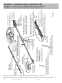
TYPICAL ONE PIECE DOOR INSTALLATION
............ FOR HELP-1.800.354.3643 OR WWW.GENIECOMPANY.COM
INSTALLATION TYPIQUE D’UNE PORTE DE GARAGE D’UNE PIÈCE ..............POUR OBTENIR DE L’AIDE-1.800.354.3643
INSTALACIÓN HABITUAL DE PUERTA DE UNA SOLA PIEZA .....................................PARA OBTENER AYUDA, LLAME AL 1.800.354.3643
*Direct wiring of power supply to opener must be installed by a licensed electrician.
*Le câblage direct de l'alimentation électrique à l’ouvre-porte doit être installé par un électricien agréé.
*Un electricista autorizado debe instalar el cableado directo del suministro de energía hacia el abridor.
TYPICAL SUPPORT BRACKET (NOT PROVIDED)
SUPPORT TYPIQUE (NON FOURNI)
ESCUADRA DE SOPORTE TÍPICA (NO SE INCLUYE)
HEADER BRACKET MOUNTING BOARD
PLANCHE DE MONTAGE FACULTATIVE POUR
SUPPORT D’EMBASE
TABLERO DE MONTAJE DE SOPORTE DEL TRAVESAÑO
POWER CORD* (APPROX.
45 IN.) TO 120V
GROUNDED OUTLET
CÂBLE D’ALIMENTATION*
(ENVIRON 45 PO.) À PRISE
DE CONTACT DE 120V À
CONTACT DE MISE À LA
TERRE
CABLE DE ALIMENTACIÓN*
(45 PULG. APROX.) A UN
TOMACORRIENTE DE 120 V
CONECTADO A TIERRA
LIFT SPRING
RESSORT DE LEVAGE
RESORTE DE ELEVACIÓN
OR
E
U DOOM S BST
U
NO
H N TED
LE
FIG. 3-2
SAFE-T-BEAM® SENSORS
PALPEURS de SAFE-T-BEAM®
SENSORES SAFE-T-BEAM®
WARNING
To reduce the risk of injury to persons or damage to property Use this opener only with a one piece or sectional door.
AVERTISSEMENT
Pour diminuer le risque de blessures corporelles ou
d’endommagement matériel - Utiliser cet l’ouvreur uniquement
avec les portes à section.
ADVERTENCIA
Para reducir el riesgo de lesión a las personas o daños a la propiedad Use este abridor solamente con puertas en secciones.
©2010
The Genie Company
ONE PIECE DOOR
PORTE D’UNE PIÈCE
PUERTA DE UNA SOLA PIEZA
01/27/2010
SECTIONAL DOOR
PORTE SECTIONELLE
PUERTA SECCIONAL
11
12
©2010 The Genie Company
01/27/2010
R
DOO
O
OT
OM
W
A
C
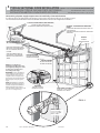
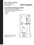
Sectional Door, Door Arm Assembly
Porte en section, Montage du bras de la porte
Puerta seccional, Conjunto del brazo de la puerta
Door Arm
Bras de la porte
Brazo de la puerta
R
CE
Release Handle
Poignée de déverrouillage
Palanca de liberación
Door Arm
Bras de la porte
Brazo de la puerta
Tensioner (located inside rail)
Tendeur (situé à l'intérieur du rail)
Tensor (ubicado dentro del riel)
See GREEN bag for parts
Voir le sac VERT pour des pièces
Vea el bolso VERDE para las piezas
Clip
Étrier
Abrazadera
One Piece Door, Door Arm Assembly
Porte d’une pièce, Montage du bras de la porte
Puerta de una sola pieza, Conjunto del brazo de la puerta
Header Bracket
Embase support
Soporte del travesaño
Rail Connector
Maillon de junction du rail
Conector del riel
Support Bracket (for extended PRO rails only)
Support (seulement pour les rails PRO étendus)
Escuadra de soporte (sólo para rieles PROFESIONALES extendidos)
Clevis Pin, Long
Axe de chape, longue
Pasador de grillete, largo
Rail Connector
Maillon de junction du rail
Conector del riel
RETAIL RAIL
RAIL DE DETAIL
RIEL DE VENTA AL MENUDEO
FIG. 3-3
Chain or belt (located inside rail)
Chaîne ou courroie
(qui se trouve à l'intérieur du rail)
Cadena o correa (ubicada dentro del riel)
Carriage Slide (located inside rail)
Coulisse du chariot (situé à l'intérieur du rail)
Deslizamiento del carro (ubicado dentro del riel)
Engage chain or belt bullet to Carriage Slide
Embrayez la chaîne ou la courroie balle
à la coulisse du chariot
Enganche la cadena o correa bala al deslizamiento del carro
Bullet
Balle
Bala
PROFESSIONAL INSTALLER RAIL
RAIL PROFESSIONNEL D'INSTALLATEUR
CARRIL PROFESIONAL DEL INSTALADOR
POWER HEAD
TÊTE DE PUISSANCE
CABEZA DE LA ENERGÍA
Power Cord
Cordon de secteur
Cable eléctrico
See BLUE bag for screws
Voir le sac BLEU pour des vis
Vea el bolso AZUL para los tornillos
REFERENCE - POWER HEAD & RAIL ASSEMBLED VIEW
RÉFÉRENCE – VUE DE LA TÊTE D’ALIMENTATION & DU RAIL ASSEMBLÉ
REFERENCIA - VISTA DEL CABEZAL ELÉCTRICO Y RIEL ENSAMBLADOS
NOTE: Use wall console and safety sensors provided with this unit. Do NOT substitute wall console or safety sensors.
REMARQUE: Utilisez la console sur le mur et les capteurs de sécurité fournis avec cet appareil. NE PAS substituer la console du mur ou les capteurs de sécurité.
NOTA: Use la consola de pared y los sensores de seguridad proporcionados con esta unidad. NO sustituya la consola de pared ni los sensores de seguridad.
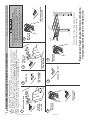
4
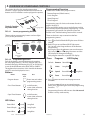
OVERVIEW OF POWER HEAD CONTROLS
This section describes the simple programming
functions. Use this page to familiarize yourself with the
buttons and LED indicators used to program the opener.
PROG
RAM
+
S ET
To garage door
Locate programming buttons
There are three programming buttons and two lights
(LEDs) on the power head.
Facing
Garage Door
ROUND
LED Indicator
(Light)
PROGRAM
Close
Travel
Button
Open
Travel
Button
SET
LONG
LED Indicator
(Light)
FIG. 4-2
Each of the buttons are used to enter and complete
the setup programming. The LEDs indicate status or a
function change by illuminating ON, OFF, or ON flashing
in one of three different colors; BLUE, RED, or PURPLE.
Throughout the instructions in this manual the buttons
and LEDs are also displayed as icons.
Buttons
Shape
Programming steps for Limits and remotes found on
pages 6 through 9.
*Force and Speed settings are set at the factory and do
not normally require adjustment programming. Custom
programming instructions for Speed and Force are
located in the Troubleshooting Section of this manual.
These are the basic steps to enter into the four
programming menus:
PROGRAM
1. Press and hold till both BLUE lights come ON then
release.
2. Both LEDs go out and Round BLUE light comes
ON. You are in the Program Menus at the Remote
Programming.
By using the or the button you can advance to
the Limits, Speed, or Force program menus and the
LED display will change accordingly.
Each program menu has a specific LED display.
SET
Press
Programming buttons
Name
There are four Power Head program menus:
Remote Program (Default menu)
Limits Program
Speed Program*
Force Program*
—
Controls location
on power head.
FIG. 4-1
Programming Overview
Use
Program
Default
LED Display
Remote
Round Blue
Limits
Long Blue
X2
Speed
Round Blue
X3
Force
Round Red
&
Long Blue
PROGRAM
PROGRAM
Program button
SET
Enters into and selects
programming menus
3. Press button to enter into the program menu
functions.
SET
If you have entered into an unwanted program
menu, press button again to exit the programming
functions.
PROGRAM
multi-function;
moves door, advances
through menus
Close Travel button
Programming function will time out after 30 seconds
if there is no key stroke activity.
multi-function;
moves door, advances
through menus
Open Travel button
LED Colors
Round Red
and
Long Red
Round Purple
and
Long Purple
Round Blue
and
Long Blue
©2010
SET
The Genie Company
01/27/2010
13
5
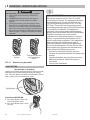
OVERVIEW - REMOTES AND OPTIONS
WARNING
A moving door can cause serious injury or death.
1. Keep people clear of opening while door is
moving.
2. Do NOT allow children to play with opener,
including wall console, remote, or wireless
keypad.
3. During programming, the door opener could
begin to run, so keep people and objects away
from the moving door and its parts. To keep the
door from moving, close the door and disconnect
it from the rail carriage by pulling the Emergency
Release Handle. See page 18 for Release Handle
operation.
Three Button
Remote
FIG. 5-1
Three button Remote
with Panic Button
feature
Remote (vary by model)
FCC and IC CERTIFIED
This device complies with FCC Part 15 and RSS
210 of Industry Canada. This equipment has been
tested and found to comply with the limits for a
Class B digital device, pursuant to Part 15 of the
FCC Rules. These limits are designed to provide
reasonable protection against harmful interference
in a residential installation. This equipment
generates, uses and can radiate radio frequency
energy and, if not installed and used in accordance
with the instructions, may cause harmful
interference to radio communications. However,
there is no guarantee that interference will not
occur in a particular installation. If this equipment
does cause harmful interference to radio or
television reception, which may be determined
by turning the equipment OFF and ON, the user is
encouraged to try to correct the interference by
one or more of the following measures:
• Re-orient or relocate the receiver antenna.
• Increase the separation between the opener and
receiver.
• Connect the opener into an outlet on a circuit
different from that to which the receiver is
connected.
• Consult your local dealer.
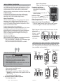
PANIC BUTTON
(Not available on all models)
Openers and remotes equipped with this feature provide
additional security when exiting/entering the garage
area. The Panic Button is located on the remote as shown
below. Alarm will sound from power head.
Panic Button
Panic Button OPERATION
1. Press Panic Button. Alarm will
sound from power head.
2. Press Panic Button again. Alarm
will stop.
14
©2010 The Genie Company
01/27/2010
INTELLICODE® FEATURES
Earlier models of Genie® garage door openers,
remotes, and wireless keypads use IntelliCode®
1 signals to communicate. Remote(s) provided
with this unit will transmit either IntelliCode® 1 or
IntelliCode® 2 signals.
Remote(s) contained in this package are preset
to IntelliCode® 2 and can be configured to
communicate with previously installed IntelliCode®
1 openers. This dual IntelliCode® option allows one
IntelliCode® 2 remote to operate BOTH new and
current models of The Genie Company garage door
openers.
This new Genie® garage door opener will ONLY
accept signals from a remote sending IntelliCode® 2
signals or a Genie® brand IntelliCode® 1 remote that
has been programmed to the opener using a new
IntelliCode® 2 remote.
NOTE: Other remotes not enabled with Genie®
IntelliCode® 2 will not operate this opener.
If you have garage door
openers*
Programming to previously installed Series II
(IntelliCode® 1) Genie® garage door openers
Remote(s) provided with this unit can operate
earlier (Series II) models of Genie® garage door
openers. The default Series III (IntelliCode® 2)
frequency must be changed to IntelliCode® 1.
(Follow these same steps to change IntelliCode® 1
back to IntelliCode® 2 frequency.)
The LED color displayed on the remote indicates
the IntelliCode® transmitting mode.
Red = IntelliCode® 1 / Green = IntelliCode® 2
1. Select a button on the remote that has NOT been
programmed to the new power head.
2. Press and hold that button for 10 seconds.
Both Red and Green
LEDs come ON and stay
ON.
10 SECS
Best choice of
IntelliCode®
programming
Use IntelliCode® 2
One or more IntelliCode® 2
openers.
Maximum 3 different openers
Mixture of openers
Use IntelliCode® 2
manufactured between 1997 and/or 1
and 2010 (IntelliCode® 1) and
new IntelliCode® 2 openers
One or more openers
Use IntelliCode® 1
manufactured between 1997
and 2010 (IntelliCode® 1)
* Maximum 3 different openers per each 3 button
remote.
3. Press the same button
twice to toggle IntelliCode®
selection from IntelliCode® 2
to IntelliCode® 1.
4. Press the same button again
to confirm toggle. The
IntelliCode® selection for this
button is set to IntelliCode® 1.
5. Take the remote to the earlier Genie® garage
door opener and follow that opener's instructions
to program a new remote.
Repeat for other Genie® garage remote(s) as
necessary.
Red LED
Green LED
Three button
remote
©2010
The Genie Company
01/27/2010
15
LOST OR STOLEN REMOTE - CLEARING MEMORY
Clearing remotes from power head memory will
clear ALL programmed remotes and wireless
keypad.
NOTE: Follow the PROGRAM REMOTE TO POWER
HEAD steps to reenter remaining or new remotes.
PROGRAM
1. Press and hold
until both lights
come ON blue.
Release button.
PROG
RAM
+
SET
S ET
—
5 SECS
2.
Lights go out and
Round BLUE light comes ON.
PROGRAM
3. Press again and
both lights flash
purple.
4. Press both and
simultaneously on the
power head and hold for
5 seconds.
PROG
RAM
+
S ET
—
5 SECS
• Test a remote operation. Remote will not
activate door opener.
• Garage door opener will operate normally using
wall console.
• Program remaining or new remotes as shown
on page 8. Your door opener will no longer
recognize any signal received from the missing
remote, or any other which has not been
reprogrammed to the power head.
SET
PROG
RAM
+
S ET
—
TRANSMITTER COMPLIANCE STATEMENT
Transmitters comply with all United States and Canadian legal requirements as of the date of manufacture.
No warranty is made that they comply with all legal requirements of any other jurisdiction. If transmitters
are to be used in another country, the importer must determine compliance with any local laws and
regulations which may differ from United States and Canadian requirements prior to use.
Los transmisores cumplen con todas las reglamentaciones legales de los Estados Unidos y del Canadá, en
la fecha de fabricación. Ninguna garantía se da que cumplan con todas las reglamentaciones legales de
ninguna otra jurisdicción. Si los transmisores se van a utilizar en otro país, el importador debe determinar
si cumplen con las reglamentaciones y leyes locales que puedan ser diferentes a las reglamentaciones de
los Estados Unidos y del Canadá, antes de usar los mismos.
Les émetteurs sont conformes à la réglementation américaine et canadienne à compter de leur date de
fabrication. Aucune garantie n’est stipulée indiquant qu’ils sont conformes à toutes les prescriptions
juridiques d’autres autorités. Si les émetteurs sont utilisés dans d’autres pays, il incombe à l’importateur
d’en déterminer leur conformité aux lois et règles locales pouvant différer de celles des États-Unis et du
Canada avant toute utilisation desdits émetteurs.
Sendegeräte entsprechen allen gesetzlichen Bestimmungen in den USA und Kanada zum Zeitpunkt der
Herstellung. Wir übernehmen keine Gewährleistung für die Einhaltung aller gesetzlichen Bestimmungen
in anderen Ländern. Sollen Sendegeräte in anderen Ländern eingesetzt werden, so muss der Importeur
vor dem Gebrauch sicherstellen, dass die Sendegeräte auch solchen lokalen Bestimmungen entsprechen,
welche von den Bestimmungen der USA und Kanadas abweichen.
16
©2010 The Genie Company
01/27/2010
6 MAINTENANCE & TROUBLESHOOTING
FOR HELP-1.800.354.3643 OR WWW.GENIECOMPANY.COM
If you have any questions, please do not hesitate to contact customer service at: 1.800.354.3643
IMPORTANT SAFETY INSTRUCTIONS
WARNING:To reduce the risk of severe injury or death:
1. READ AND FOLLOW ALL INSTRUCTIONS.
2. Never let children operate or play with the door controls. Keep the remote away from children.
3. Always keep the moving door in sight and away from people and objects until the door is completely closed. NO
ONE SHOULD CROSS THE PATH OF THE MOVING DOOR.
4. NEVER GO UNDER A STOPPED, PARTIALLY OPEN DOOR.
5. Test opener monthly. The door MUST reverse on contact with a 1-1/2" high object (or a 2" x 4" board laid flat)
at the center of the doorway on the floor. After adjusting either the force or the limit of travel, retest the door
opener. Failure to adjust the opener properly may cause severe injury or death.
6. When possible, use the emergency release only when the door is closed. Use caution when using this release
with the door open. Weak or broken springs are capable of increasing the rate of door closure and increasing the
risk of severe injury or death.
7. KEEP DOORS PROPERLY BALANCED. See your garage door Owner’s Manual. An improperly balanced door
increases the risk of severe injury or death. Have a trained door system technician make repairs to cables, spring
assemblies, and other hardware.
8.
SAVE THESE INSTRUCTIONS.
WARNING
• Garage door hardware (springs, cables, brackets,
pulleys, etc.) are under extreme pressure and
tension.
• DO NOT attempt to repair or adjust door
springs or any hardware, and DO NOT OPERATE
garage door automatically or manually if door
is improperly balanced or springs are broken.
– CONTACT A TRAINED DOOR SYSTEM
TECHNICIAN.
ROUTINE MONTHLY MAINTENANCE
Basic monthly maintenance tasks.
• Door balance
• Safe-T-Beam® System Check
• Contact reverse
Instructions for these tasks and others are found on
the following pages.
WARNING
Use wall console supplied with opener. Any
other wall console can cause the opener to
operate unexpectedly.
Safe-T-Beam® (STB) SYSTEM CHECK
• STB Red and Green LEDs ON steady, system OK
FROM STBs
• STB Red LED flashes
FROM WALL
– Check for obstruction
CONSOLE
– Check alignment
– Verify wire routing from STBs
to STB connection in power
head
– Check for signal interference
from another Safe-T-Beam®
STB
BWC
IWC
unit
• No STB Red or Green LED displayed
– Check wiring and wire connections
NOT
USED
NOT
USED
DOOR BALANCE (SPRING TENSION)
• With the door closed, pull
release handle
DOWN and let go to release door carriage
assembly from drive system.
• Raise door manually approximately 3’- 4’ and
release.
– Door should remain stationary or move very
slightly.
– If door moves quickly, CONTACT A TRAINED
DOOR SYSTEM TECHNICIAN.
• Close the door.
• Pull emergency release handle DOWN and let go
to engage carriage assembly to drive system.
– Operate door using remote or wall console.
– Door will re-attach itself to carriage assembly.
©2010
The Genie Company
3’ - 4’
Sectional Door
FIG. 6-1
01/27/2010
3’ - 4’
One-Piece Door
Door balance
17
CONTACT REVERSE TEST
The Force and Limit settings MUST be
COMPLETED before testing.
1. Testing.
• Open garage door using wall console.
– Place a 2" x 4" board (laid flat) under center of
garage door opening (Fig. 6-2).
• Close garage door using wall console.
• When door contacts board, the door must
stop (within 2 seconds) and reverse direction
returning to open position.
2. Adjustment.
• If the door does not reverse.
– Check to see if door has "down" limit properly
set in the fully closed position. It should not
have reached its "close" limit before hitting
board. Reprogram close limit with door
completely closed.
– If the door STOPS but does not reverse, reset
your limits. Remove board. Return to pages
6-7 and repeat Limits settings to correct down
limit.
• Test again. Repeat as necessary until door
reverses upon contacting board.
RESET - OPEN/CLOSE TRAVEL LIMIT
Performing all ten (10) Limits/Force setting steps
(pages 6-7) erases previous Limits/Force settings.
NOTE: The opener will not close the door
automatically unless the Safe-T-Beam® System is
installed and Limits are programmed.
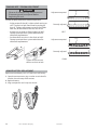
CARRIAGE ENGAGE/DISENGAGE
Use Release Handle to manually engage or
disengage Carriage.
TO RELEASE CARRIAGE:
1. Pull DOWN on handle and let go.
2. Verify RED block is showing.
3. Raise or lower door manually.
Release Handle
DOOR
N
OTIC
FDO
ORB
E
CO
PULL MESOB
DOWN
ST
ONHA RUCTED
NDLE
PULL
TO ENGAGE CARRIAGE:
1. Pull DOWN on handle and let go.
2. Verify RED block is NO LONGER showing.
3. Raise or lower door using remote or wall console.
FIG. 6-3
FIG. 6-2
Disengage Carriage
2 x 4 under center of door opening
WHEN RED BLOCK IS SHOWING
CARRIAGE IS UNLOCKED
MOTION DETECTOR - OVERVIEW
(Not available on all models)
Power heads equipped with a motion detector
sensor provide additional security when
exiting or entering the garage area.
NOTE: Sensor positioning on the power head does not
provide motion monitoring above the power head.
OPERATION
• Motion detector sensor is always ON. There are NO
user controls or adjustments.
• Lights automatically turn ON when motion is
detected and will turn OFF after 4 minutes of no
motion.
• Motion detector sensor will not turn OFF lighting
turned ON at the wall console.
• Lighting turned ON at the wall console will remain
ON until wall console turns lighting OFF or opener
is used.
or
LOCKED
UNLOCKED
FIG. 6-4
Carriage
(Standing below rail looking up at
carriage)
Motion Detector Sensor
PROGRAM
T
18
— +
©2010 The Genie Company
01/27/2010
WALL CONSOLE - OVERVIEW
Use only the Series III wall console provided with this
unit. Wall consoles from other manufacturers will not
work with this power head. Earlier Genie® Series II
wall consoles will not work with this power head.
Wall console has three buttons and one indicator light.
Indicator Light
Indicator light will display red when wall console
is properly wired and Vacation Lock is OFF. When
Vacation Lock is ON indicator light flashes.
Open/Close Button
Use this button to open or close garage door. When
Vacation Lock is ON the Open/Close button will
CLOSE door only. Note: Constant button pressure in
the CLOSE mode will override error responses in the
power head and close door.
Independent Light Control Button
Use this button to turn power head lights ON. Power
head lighting will remain ON until this button is
pressed again or a door action has been completed.
Note: If opener has a Motion Detector sensor the
sensor will keep power head lights ON as long as
motion is detected.
Vacation Lock Button
When Vacation Lock is ON the power head cannot be
activated by the wall console or a remote.
• Press and hold for 5 seconds (or till Indicator Light
flashes) to activate Vacation Lock.
• Press and release to turn Vacation Lock OFF.
Open/Close Button
Open and closes door from inside garage
Vacation Lock Button
– LOCK disables controls
after door is completely
closed
– UNLOCK allows controls to
work normally
Indicator Light
Red indicator light is always ON
When Vacation Lock is ON the
indicator light flashes
Independent Light Control Button
– Controls door opener lights from inside garage
– Shuts OFF lights 4 minutes after door action
Tip: If indicator light on wall console comes ON, but
there is NO
FROM STBs
FRO
OM STBs
FROM WALL
ROM
OM W
WA
FROM
WALL
operation from
CONSOLE
ONSO
OLE
CONSOLE
buttons - verify
wall console
wire routing
at power head
connector.
NOT
USED
STB
BWC
IWC
STB
BWC
NOT
USED
IWC
OPTIONAL DUAL WALL CONSOLE - INSTALLATION
Use only the Series III wall console provided with this
unit. An optional second Genie® Series III wall console
(not provided) can be added.
TO
POWER HEAD
TO WALL CONSOLE #1
FROM STBs
FROM WALL
CONSOLE
CHANGE LIGHT BULBS
WARNING
• Observe all safety warning and precautions!
Improper light bulb removal or replacement
could result in Death or Serious Injury.
• Disconnect power from opener before
beginning this task.
• When replacing light cover, make sure wires are
not pinched or near moving parts.
1. Disconnect power to door opener.
• Open power head light cover.
• Remove light bulb(s).
• Replace with maximum 100 Watt light bulbs.
– Do NOT use light bulbs with greater than 100
Watt rating.
• Close power head light cover.
2. Reconnect power to door opener.
• Test light operation.
©2010
The Genie Company
NOT
USED
NOT
USED
B/W W
STB
BWC
B/W W
IWC
WALL
CONSOLE #1
WALL
CONSOLE #2
OR
BOTH TO POWER HEAD
FROM STBs
FROM WALL
CONSOLE #1
FROM WALL
CONSOLE #2
NOT
USED
STB
BWC
NOT
USED
B/W W
IWC
WALL
CONSOLE #1
01/27/2010
B/W W
WALL
CONSOLE #2
19
CHAIN OR BELT - TENSION ADJUSTMENT
WARNING
• Observe all safety warning and precautions!
• Disconnect power from opener before
beginning this task.
Adjustment required
Visually inspect the chain or belt once per year.
• At the center of the rail, is chain or belt resting on
rail? The chain or belt should not be resting on
the rail. Tighten adjustment nut until chain/belt
does not, at the center of the rail, rest on rail.
• Is there rust on chain or frayed edges on belt?
Contact a trained door system technician for
chain/belt replacement.
• Are there kinks or twists in the chain or belt?
Contact a trained door system technician for
chain/belt replacement.
Belt
Belt
Correctly adjusted
Belt at center of rail
BELT
Adjustment required
Chain
Chain
Correctly adjusted
Chain at center of rail
Tighten nut to increase
tension on chain or belt
CHAIN
REMOTE BATTERY REPLACEMENT
Replace remote battery with a CR 2032 coin cell battery.
1. Open the remote case using a washer or coin that fits
into the slot at the top of the remote.
2. Replace battery.
3. Align components and snap case closed.
20
©2010 The Genie Company
01/27/2010
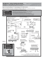
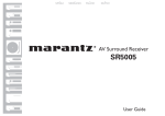
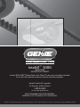
REFERENCE - CIRCUIT WIRING DIAGRAM
FOR HELP-1.800.354.3643 OR WWW.GENIECOMPANY.COM
RÉFÉRENCE - DIAGRAMME DE CÂBLAGE DE CIRCUIT .........................................................POUR OBTENIR DE L’AIDE-1.800.354.3643
REFERENCIA - ESQUEMA ELÉCTRICO DEL CIRCUITO ........................................................PARA OBTENER AYUDA, LLAME AL 1.800.354.3643
Opener circuit wiring diagram. This wiring diagram is for reference only.
Schéma de câblage de l’ouvreur. Ce schéma de câblage est indiqué à titre de référence uniquement.
Diagrama del circuito del operador. Este diagrama es sólo para referencia.
Opening Cover May Cause Electric Shock.
L’ouverture du couvercle peut entraîner des chocs électriques.
Abrir la tapa puede causar choques eléctricos.
Disconnect power from opener prior to removing cover.
Coupez l’alimentation de l’ouvre-porte avant de retirer le couvercle.
Desconecte la electricidad del abrepuertas antes de quitar la cubierta.
WARNING
AVERTISSEMENT
ADVERTENCIA
SURGE PROTECTOR (MOV)
POWER CORD
LIMITEUR DE SURTENSION
PROTECTOR DE SOBRETENSIONES
CORDON DE SECTEUR
CABLE ELÉCTRICO
CONNECTOR
CONNECTEUR
CONECTADOR
SCREW DRIVE MOTOR
IMPULSIÓN DEL
TORNILLO MOTEUR
COMMANDE DE VIS MOTOR
CHAIN/BELT MOTOR
PRINTED CIRCUIT BOARD
CADENA/CORREA MOTEUR
CHAÎNE/COURROIE MOTOR
CIRCUIT IMPRIMÉ
CIRCUITO IMPRESO
WHITE
BLANC
BLANCO
RED
BLACK
ROUGE
ROJO
NOIR
NEGRO
RED
BLACK
NOIR
NEGRO
ROUGE
ROJO
BLACK
NOIR
NEGRO
BLACK
1
NOIR
NEGRO
GREEN
VERT
VERDE
2
3
4
BLACK
NOIR
NEGRO
STB
1
BWC
2
3
(IWC or AWC)
4
5
6
STRIPED WHITE
STRIPED WHITE
CHOKE
BLANC RAYÉ
BLANCO RAYADO
BLANC RAYÉ
BLANCO RAYADO
BOBINE D'ARRÊT
BOBINA DE CHOKE
WHITE
BLANC
BLANCO
STRIPED WHITE
WHITE
BLANC
BLANCO
BLACK
PHOTODÉTECTEUR
FOTOSENSOR
NOIR
NEGRO
BLACK
7
6
5
4
FIG. 6-5
3
2
1
NOIR
NEGRO
SONDE DE MOUVEMENT
SENSOR DE MOVIMIENTO
2
RED
AVERTISSEMENT
ADVERTENCIA
ROUGE
ROJO
3
COMMANDE MURAL
CONTROL DE LA PARED
(Purchased Separately)
BATTERY BACKUP
JAUNE
AMARILLO
SUPPORT DE BATTERIE
RESPALDO DE BATERÍA
OPTICAL SENSOR*
SONDE OPTIQUE
SENSOR ÓPTICO
1
2
3
2
3
4
5
6
7
4
RED
The Genie Company
WALL CONTROL
NOIR
NEGRO
YELLOW
GREEN
ROUGE
ROJO
©2010
COMMANDE MURAL
CONTROL DE LA PARED
BLACK
1
ELECTRICAL SHOCK
CHOC ÉLECTRIQUE
CHOQUE ELÉCTRICO
(Purchased Separately)
ADVANCED WALL CONTROL
MOTION SENSOR*
1
WARNING
BLANC RAYÉ
BLANCO RAYADO
PHOTO SENSOR
VERT
VERDE
12 VDC
55 VDC
*SOME MODELS DO NOT COME WITH THIS FEATURE
QUELQUES MODÈLES NE VIENNENT PAS AVEC CETTE CONFIGURATION
ALGUNOS MODELOS NO VIENEN CON ESTA CARACTERÍSTICA
01/27/2010
21
ADJUSTMENT GUIDE - SPEED SETTINGS
Speed settings are pre-programmed at the factory
for the maximum speed. Speed settings should not
need adjustment with this unit.
However, travel speed for the opener can be
adjusted to slower speeds to minimize normal wear
for heavy sectional doors.
NOTE: One piece doors are automatically set during
Limits programming to the slowest speed and
opener speed cannot be reset for one piece doors.
FOR HELP-1.800.354.3643 OR WWW.GENIECOMPANY.COM
CHANGE SPEED SETTING
Use this guide to ADJUST power head SPEED settings.
There are three (3) Speed settings available on this
unit. Door type (one piece or sectional), door weight
and balance, and condition of door components /
track affect door speed. Speed adjustment may not
be available for some installations depending on
these factors.
PROGRAM
1. Press on the power head and hold till both
lights turn steady ON. Release button.
Lights go out and Round BLUE light comes ON.
SET
2. Press two times and the Round BLUE and Long
BLUE lights come ON.
PROGRAM
3. Press once to enter the Speed Programming
menu. The current Speed setting will display on
the LEDs. See table below.
SET
4. Press to raise or to lower UP Speed settings
within the available range.
NOTE: Faster door speeds may not be available.
PROGRAM
5. Press
SET
to set UP Speed level.
6. Press to raise or to lower DOWN Speed
settings within the available range.
NOTE: Faster door speeds may not be available.
PROGRAM
7. Press to set DOWN Speed level and to exit
Speed menu. Both LEDs flash BLUE to confirm.
SET
Power Head LEDs
Speed Level
Round LED
Long LED
Default LED display is the current Speed setting
Red
LED Speed indicator colors
Purple
Blue
Red
Purple
Blue
Speed Level LED indicator colors
Red
ON
Purple
ON
Blue
ON
MAXIMUM
MID
SLOW
22
©2010 The Genie Company
01/27/2010
Red
ON
Purple
ON
Blue
ON
ADJUSTMENT GUIDE - FORCE SETTINGS
FOR HELP-1.800.354.3643 OR WWW.GENIECOMPANY.COM
CAUTION
Door closing force is FACTORY set and requires no
adjustment for normal operation.
• Never increase the door closing force to
compensate for a damaged door or a binding
door track.
• Never adjust force to compensate for a broken
door spring.
• Perform monthly CONTACT REVERSE TEST as
described on page 1.
Force settings are pre-programmed at the factory
and "learned" during the Open/Close Limit settings
steps. For normal use Force settings should not
need adjustment with this unit.
However, conditions that might suggest an
adjustment is necessary are;
Doors with very stiff weather seals
Doors that start down, then STOP and reverse
before it is closed
Doors that start up, but STOP before it is
completely open
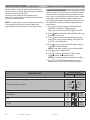
CHANGE FORCE SETTING
Use this guide to ADJUST power head FORCE settings.
NOTE: There are nine (9) force levels. Not all force
levels are available on all models.
Some models come with a reduced range of force
levels. On these models you can adjust Force
settings only within the reduced range.
1. Press on the power head and hold till both
lights turn steady ON. Release button.
Lights go out and Round BLUE light comes ON.
2. Press three times and Round RED light comes
ON. (These Force settings do not scroll.)
3. Press once to enter the Force Programming
menu. The power head LEDs will display the
current Force setting. See table below.
4. Press to raise or to lower UP Force settings
within the available range. (If lower UP Force
setting is good skip to Step 5.)
5. Press to set UP Force level.
6. Press to raise or to lower DOWN Force
settings within the available range. (If lower
DOWN Force setting is good skip to Step 7.)
7. Press to set DOWN Force level and to exit Force
menu. Both LEDs flash BLUE to confirm.
PROGRAM
SET
PROGRAM
SET
PROGRAM
SET
PROGRAM
SET
Power Head LEDs
Force Level
Round LED
Long LED
Default LED display is the current Force setting
LED indicator colors
OFF,
Blue,
Purple,
Force Level 1
Force Level 2
Force Level 3
Force Level 4
Force Level 5
Force Level 6
Force Level 7
Force Level 8
Force Level 9
©2010
The Genie Company
01/27/2010
Red
Force Level LED indicator colors
Blue
OFF
ON
Blue
OFF
ON
Blue
Blue
ON
ON
Purple
OFF
ON
Purple
OFF
ON
Purple
Purple
ON
ON
Red
OFF
ON
Red
OFF
ON
Red
Red
ON
ON
23
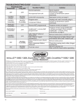
TROUBLESHOOTING GUIDE - OPERATION
PROBLEM
Opener does NOT run
from wall console.
Opener runs, but door
does NOT move.
Opener works from
wall console, but NOT
from remote.
Remote has less than
25 feet operating
range or no operation.
Door starts down,
then STOPS and goes
back up.
OR
Safe-T-Beam® System
malfunction.
Door starts down,
then STOPS before it
is closed.
OR
Door will only open.
Door starts up, but
STOPS before it is
completely open.
Door will only run
closed.
24
FOR HELP-1.800.354.3643 OR WWW.GENIECOMPANY.COM
WHAT TO DO
• Check power source.
– Plug a lamp into outlet used for power head. If lamp works, power source is OK.
– If not, check fuse or circuit breaker.
• If power is OK.
– Check connections at power head terminals and at wall console.
– Limits must be set with door arm connected to door.
• Check if wall console Vacation Lock is ON. Turn Vacation Lock OFF & check operation.
• Check for reversed, broken, or cut wires. Staples can cut insulation and short wires.
Repair or replace.
• Make sure carriage is engaged to chain or belt bullet. See pages 12 and 18. Refer to
Installation poster or download poster from WWW.GENIECOMPANY.COM.
– Ensure carriage is in engaged position. See page 18.
• Check to make sure chain/belt is not broken or OFF its pulley. See page 20.
• Check FORCE ADJUSTMENT. See page 23.
• Check all remotes.
• Replace remote battery with good one. See page 20.
• Program remote to power head. See pages 8-9.
• Relocate remote inside car and or point remote at garage door.
• Replace battery. See page 20.
• Reposition door opener antenna.
• Remote LED does not come ON with button push - replace battery. See page 20.
• Eliminate possible competing signals (satellite radio, FiOS® TV).
• If a NEW installation, check Door Arm position. Refer to Installation poster or download
poster from WWW.GENIECOMPANY.COM.
• Check if Limits are properly set. See pages 6-7.
• Check if Safe-T-Beam® Red LED is flashing. See page 17.
• Check Safe-T-Beam® system for beam obstruction or misalignment of lenses. See page 17.
• Check garage door for binding.
• If an operational problem exists, and opener will not run closed. The opener can
be forced to close as follows; Press and hold the wall console button until door is
completely closed.
• Check for interference from adjacent Safe-T-Beam® units.
• Contact The Genie Company at 1.800.354.3643.
• Check Safe-T-Beam® wire connections at power head. See page 17.
• Check Limits are properly set. See pages 6-7.
• Check CONTACT REVERSE. See page 18.
• Check garage door for binding.
• Check closing "FORCE" adjustment. See page 23.
• Check Limits are properly set. See pages 6-7.
• Check opening "FORCE" adjustment. See page 23.
• Be sure door, opener, and springs are in good repair, properly lubricated and balanced.
•
WARNING: If you suspect a problem with the garage door hardware or springs,
contact The Genie Company at 1.800.354.3643.
• Check Limits are properly set. See pages 6-7.
• Check Vacation Lock. Vacation Lock should be OFF for normal operation. See page 19.
• Check door balance, condition, and door spring.
• Check opening "FORCE" adjustment. See page 23.
•
WARNING: If you suspect a problem with the garage door hardware or springs,
contact The Genie Company at 1.800.354.3643.
©2010 The Genie Company
01/27/2010
TROUBLESHOOTING GUIDE - OPERATION (CONTINUED) ..................................................................... FOR HELP-1.800.354.3643
PROBLEM
WHAT TO DO
Door opener starts for
no reason.
Noisy operation.
Door opener runs
slow
• Check "CLOSE" Limit setting. See pages 6-7.
• Button stuck on wall console or remote.
• Was a remote lost or stolen? Erase all remotes from power head memory and program
new remotes. See page 8.
• Be sure all door fasteners are tight.
• Be sure garage door is in good repair, properly lubricated and balanced.
• Be sure opener is in good repair.
• Check operating condition of door. See pages 17 and 18 . Door may need professional
repair/adjustment.
• Is this opener installed on a one piece door? Normal speed for one piece door is
lowest speed setting.
• If carriage travel is less than 6 feet, opener configures programming for a one piece
door.
• Check door speed. See page 22.
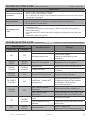
TROUBLESHOOTING GUIDE - POWER HEAD LEDs
Power Head LED
Round LED
Long LED
FOR HELP-1.800.354.3643 OR WWW.GENIECOMPANY.COM
Possible Problem
Normal operation
OFF
OFF
ON/RED/
STEADY
ON/RED/
STEADY
ON/RED/
FLASHING
ON/RED/
FLASHING
ON/BLUE/
FLASHING
OFF
ON/PURPLE/
FLASHING
OFF
ON/RED/
FLASHING
OFF
OFF
ON/RED/
FLASHING
OFF
ON/RED/
STEADY
©2010
The Genie Company
No response from unit
Solution
None required
Check power supply
Contact a trained door system
technician
Limits NOT set properly
Reprogram Limits, see pages 6-7
Program error
Unplug unit, wait 5 seconds, plug in
Contact a trained door system
technician
Component failure
Remote NOT programmed
Program remote, see page 8
IntelliCode® 1 remote NOT
programmed
Program remote using IntelliCode®
2 remote, see page 8, then program
IntelliCode® 1 remote using
instructions on page 9
Safe-T-Beam® physical
obstruction
Safe-T-Beam® signal
interference
Door contact in up or down
travel
Door component failure
detected
Thermal cutout
01/27/2010
Remove obstruction, recheck unit
Check alignment of Safe-T-Beam® pair
and nearest other Safe-T-Beam® pair
Remove obstruction
Check door spring, track, rollers, hinges
and fixtures
DO NOT unplug unit
Wait until LED clears before operating
25
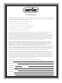
Limited Warranty
*0,+ROGLQJV,QF GED7KH*HQLH&RPSDQ\ 6HOOHU ZDUUDQWVWRWKHRULJLQDOSXUFKDVHURIWKHEHORZLGHQWLILHGJDUDJHGRRURSHQHU,QWHOOL*0RGHO
´3URGXFWµVXEMHFWWRDOORIWKHWHUPVDQGFRQGLWLRQVKHUHRIWKDWWKH3URGXFWDQGDOOFRPSRQHQWVWKHUHRIZLOOEHIUHHIURPGHIHFWVLQPDWHULDOVDQGZRUNPDQVKLS
IRUWKHIROORZLQJSHULRGVRIWLPHPHDVXUHGIURPWKHGDWHRISXUFKDVH
02725*($5%2;6HOOHUZDUUDQWVWKHPRWRUIRUWKH/,)(7,0(RIWKHSURGXFW
%(/76HOOHUZDUUDQWVWKHEHOWIRUDSHULRGRI),)7((1<($56
3$5766HOOHUZDUUDQWVDOORWKHUSDUWVDQGFRPSRQHQWVIRUDSHULRGRI),9(<($5
$&&(6625,(66HOOHUZDUUDQWVDOODFFHVVRULHVIRUDSHULRGRI21(<($5
/LIHWLPHVKDOOPHDQDVORQJDVWKHRULJLQDOSXUFKDVHURZQVWKHSURGXFW
6HOOHU·VREOLJDWLRQXQGHUWKLVZDUUDQW\LVVSHFLILFDOO\OLPLWHGWRUHSDLULQJRUUHSODFLQJDWLWVRSWLRQWKH3URGXFWRUDQ\SDUWWKHUHRIZKLFKLVGHWHUPLQHGE\
6HOOHUWREHGHIHFWLYHGXULQJWKHDSSOLFDEOHZDUUDQW\SHULRG $Q\ODERUFKDUJHVDUHH[FOXGHGDQGZLOOEHWKHUHVSRQVLELOLW\RIWKHSXUFKDVHU
7KLVZDUUDQW\JLYHV\RXVSHFLILFOHJDOULJKWVDQG\RXPD\DOVRKDYHRWKHUULJKWVZKLFKYDU\IURPVWDWHWRVWDWH 7KLVZDUUDQW\LVPDGHWRWKHRULJLQDOSXUFKDVHU
RIWKH3URGXFWRQO\DQGLVQRWWUDQVIHUDEOHRUDVVLJQDEOH 7KLVZDUUDQW\DSSOLHVRQO\WR3URGXFWLQVWDOOHGLQDUHVLGHQWLDORURWKHUQRQFRPPHUFLDODSSOLFDWLRQ ,WGRHVQRWFRYHUDQ\3URGXFWLQVWDOOHGLQFRPPHUFLDORULQGXVWULDOEXLOGLQJDSSOLFDWLRQV 7KLVZDUUDQW\GRHVQRWDSSO\WRDQ\XQDXWKRUL]HGRULPSURSHU
LQVWDOODWLRQDOWHUDWLRQRUUHSDLURIWKH3URGXFWRUWRDQ\3URGXFWRUFRPSRQHQWZKLFKKDVEHHQGDPDJHGRUGHWHULRUDWHGGXHWRPLVXVHDEXVHQHJOHFW
DFFLGHQWIDLOXUHWRSURYLGHQHFHVVDU\PDLQWHQDQFHQRUPDOZHDUDQGWHDURUDFWVRI*RGRUDQ\RWKHUFDXVHEH\RQGWKHUHDVRQDEOHFRQWURORI6HOOHUDQGGRHV
QRWFRYHUEDWWHULHVPLVVLQJRUGDPDJHGSDUWVIURPFOHDUDQFHRURSHQER[VDOHVRUUHSDLUVRUPDLQWHQDQFHWRGRRUFRPSRQHQWV
$//(;35(66$1',03/,(':$55$17,(6)257+(352'8&7,1&/8',1*%87127/,0,7('72$1<,03/,(':$55$17,(62)
0(5&+$17$%,/,7<$1'),71(66)25$3$57,&8/$5385326($5(/,0,7(',17,0(727+($33/,&$%/(:$55$17<3(5,2'
5()/(&7('$%29( 12:$55$17,(6:+(7+(5(;35(6625,03/,(':,//$33/<$)7(57+(/,0,7(':$55$17<3(5,2'+$6
(;3,5(' 6RPHVWDWHVGRQRWDOORZOLPLWDWLRQVRQKRZORQJDQLPSOLHGZDUUDQW\ODVWVVRWKHDERYHOLPLWDWLRQPD\QRWDSSO\WR\RX
,112(9(176+$//*0,+2/',1*6,1& 25,763$5(1725$)),/,$7(6%(5(63216,%/()2525/,$%/(72$1<21()2563(&,$/
,1',5(&7&2//$7(5$/381,7,9(,1&,'(17$/25&216(48(17,$/'$0$*(6HYHQLI6HOOHUKDVEHHQDGYLVHGRIWKHSRVVLELOLW\RIVXFK
GDPDJHV 6XFKH[FOXGHGGDPDJHVLQFOXGHEXWDUHQRWOLPLWHGWRORVVRIXVHFRVWRIDQ\VXEVWLWXWHSURGXFWRURWKHUVLPLODULQGLUHFWILQDQFLDOORVV 6RPHVWDWHV
GRQRWDOORZWKHH[FOXVLRQRUOLPLWDWLRQRILQFLGHQWDORUFRQVHTXHQWLDOGDPDJHVVRWKHDERYHOLPLWDWLRQRUH[FOXVLRQPD\QRWDSSO\WR\RX
&ODLPVXQGHUWKLVZDUUDQW\PXVWEHPDGHSURPSWO\DIWHUGLVFRYHU\DQGZLWKLQWKHDSSOLFDEOHZDUUDQW\SHULRG 7RREWDLQZDUUDQW\VHUYLFH\RXPXVWFRQWDFW
*HQLHFXVWRPHUVHUYLFHDQGSURYLGHSURRIRIWKHGDWHDQGORFDWLRQRISXUFKDVHDQGLGHQWLILFDWLRQDVWKHRULJLQDOSXUFKDVHU &DOO*HQLH&XVWRPHU6HUYLFH
WROOIUHHDWWRVSHDNZLWKDWUDLQHGUHSUHVHQWDWLYH 3XUFKDVHUPXVWDOORZVHOOHUDUHDVRQDEOHRSSRUWXQLW\WRLQVSHFW3URGXFWFODLPHGWREH
GHIHFWLYHSULRUWRUHPRYDORUDOWHUDWLRQRILWVFRQGLWLRQ 8SRQGHWHUPLQDWLRQE\6HOOHUWKDWWKH3URGXFWRUDQ\SDUWWKHUHRILVGHIHFWLYHGXULQJWKHDSSOLFDEOH
ZDUUDQW\SHULRGZKLFKPD\UHTXLUHSXUFKDVHUWRUHWXUQWKH3URGXFWWR6HOOHUDWSXUFKDVHU·VH[SHQVH6HOOHUZLOOVXSSO\WKHSXUFKDVHUZLWKUHSODFHPHQWSDUWV
RUDWLWVRSWLRQDUHSODFHPHQW3URGXFWVKLSSLQJDQGKDQGOLQJRIDQ\UHSODFHPHQWSDUWVRUUHSODFHPHQW3URGXFWDOVRDWSXUFKDVHU·VH[SHQVH 6HOOHUPD\XVH
QHZRUUHFRQGLWLRQHGSDUWVRUDQHZRUUHFRQGLWLRQHG3URGXFWRIWKHVDPHRUVLPLODUGHVLJQ 7KHUHDUHQRHVWDEOLVKHGLQIRUPDOGLVSXWHUHVROXWLRQSURFHGXUHVRIWKHW\SHGHVFULEHGLQWKH0DJQXVRQ0RVV:DUUDQW\$FW
385&+$6(5
,167$//$7,21$''5(66
'$7(385&+$6('
6(5,$/180%(5
23(1(502'(/
5(027(&21752/02'(/
'($/(51$0(
'($/(5$''5(66
P900-787