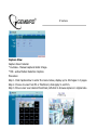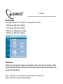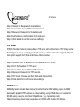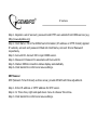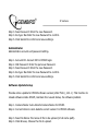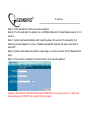
1
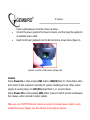
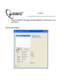
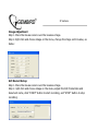
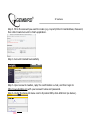
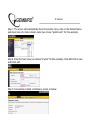
IP camera
CAM77IP LAN-controlled IP camera
IP camera
Disclaimer
•
We spared no efforts to make sure that the information in this manual is correct and
complete. However no liability is accepted for any errors or omissions. Gembird
Electronics reserves the right to change the specifications of the hardware and
software described in this manual without prior notice.
•
No part of this manual may be reproduced, transmitted or translated in any language
in any form, by any means, without the prior written permission of Gembird
Electronics Ltd.
•
Gembird Electronics makes no warranties for damages resulting from corrupted or
lost data due to a mistaken operation or malfunction of the product, the software,
personal computers or peripheral devices.
Gembird® is a registered trademark of GMB Tech (Holland) bv.
Other names or products not mentioned above may be registered trademarks or
trademarks of their respective owners.
Copyright © 2007 Gembird Electronics Ltd. All rights reserved.
IP camera
CAM77IP User manual
Introduction
Thank you for buying the Gembird® LAN-controlled IP camera with MJPEG recording,
motion detection, flash-card and night-vision support! This manual will help you install and
use it properly.
CAM77IP is an affordable and efficient remote monitoring-managing surveillance
solution. Simple installation, internal Web server, can be accessed any time - any places.
CAM77IP capable of directly connected to local and broadband network. Using internet
explorer such as IE, user can perform remote image surveillance and management task,
allowing instants grasp of the surveillance site.
Support network protocol such as: PPPoE, DHCP, Static IP, DDNS, SMTP, FTP, NTP.
CAM77IP also combined the hardware-accelerated Motion Detection and Night-Vision
function, profession the remote surveillance system with safety protection and joy of using.
CAM77IP is the most cost-efficient solution for your network surveillance product and
broadband network camera, a wise choice that you have made.
IP camera
Features
•
Remote controlled via Ethernet network (RJ45 connector)
•
Accessible via HTTP, FTP protocols, sends records by E-mail (SMTP), supports
static IP, DHCP, PPPoE, DDNS, NTP (Network Time) protocols
•
Supports recording using MJPEG coding
•
Supports storage to SD flash cards
•
Supports motion detection function
•
Supports night vision by means of the infrared LEDs
Specification
•
Resolution: 160x120, 320x240 and 640x480 pixels
•
Image quality: Fine, Normal and Basic
•
Stores captured image on PC or SD flash-card
•
Supports HTTP, FTP, SMTP, static IP, DHCP, PPPoE, DDNS, NTP protocols
•
AC-DC power adaptor: input 100-240VAC 50/60Hz; output 5V DC 800mA
•
Dimensions of camera (LxWxH): 102x70x65mm
•
Net weight of camera: 168g
IP camera
Package contents
•
IP camera with base
•
Power adaptor with 1.4m cable
•
Driver and software CD
•
2m LAN cable
System requirements
•
CPU: 1.6GHz or above
•
Operating system: Windows 2000/XP or above
•
Memory: 128MB or above (recommended 256MB)
•
Browser: Microsoft IE6.0 or above
•
Hard drive: at least 10MB disk space
IP camera
Hardware Descriptions and Connection
Product Bottom
Figure 1. CAM77IP Network Camera Bottom View
SW1: Hardware Rest
SW2: Press to restore factory default IP Address (192.168.1.100) (Press and hold more
than 5 seconds)
IP camera
Bottom Front
Lens
Lens cover
Status LED
Infrared LED
Figure 2. CAM77IP Network Camera Front View
IP camera
Connectors
Figure 3. CAM77IP Network Camera rear view
SD Storage Card
Figure 4. SD Storage Card
IP camera
Installation and configurations
Hardware Installation
Ethernet
Power
Figure 5. Installation diagram
•
Plug the Ethernet cable into the RJ-45 connector at the LAN connector as picture
shown.
•
Plug the other end of the Ethernet cable into any available LAN port. A typical
IP camera
home router/gateway connection shown as below.
•
Connect the power supply to the Power connector, and then plug the supply into
an available power outlet.
•
Insert the SD card (optional) into the SD card slot as shown below (figure 6).
Figure 6. Insertion of SD memory storage card
Caution
During Power On or while pressing SW1 button; LED(D5) flash for 3 times follow with a
short period of light out(about 5 seconds) for system reinitiating process. When system
regains its working stage, the LED (D5) should flash in a 1 second interval.
During Power ON or while pressing SW2 button; press and hold 5 seconds continuously
then release, will be restored to factory default.
Make sure your CAM77IP Network Camera are using the provided power adaptor, using
unauthorized power adaptor may due damage to the Network Camera.
IP camera
CAM_EZ SEARCH
Browse the IP camera CD. Execute the d:\Utility\CAM_EZ search program. The
CAM_EZ search can be used to manually configure the IP camera's network settings. It
may be necessary to use this tool assign an IP address for your IP camera if your IP camera
network setting need configuration. This tool is also helpful for finding all the cameras on
your network. CAM_EZ search also display the IP camera's status and link to Internet
Explorer Web control.
Note: The CAM_EZ search must be run from a PC on the local area network where the
camera to be set up is located.
Procedure:
•
Run CAM_EZ Search camera search application.
•
Modifying CAM77IP's IP and other settings, as show below:
* Name: User defined name for CAM77IP.
* IP: IP address for CAM77IP; for example, if computer's IP is 192.168.1.168,
you could set CAM77IP's IP 192.168.1.* (* = 1~254), make sure the IP
assigned don't conflict with other device in the network.
* Subnet mask: default as 255.255.255.0.
* Default Gateway: Same Default Gateway of your computer's network setting.
* HTTP Port: default as port 80.
•
After configuration, click "Submit" to renew CAM77IP network setting
•
Click "Update" to refresh CAM77IP list
IP camera
•
Access the CAM77IP setup page via Internet Explorer by double click on "your
CAM77IP list"
CAM_EZ Search diagram
IP camera
System Login
System login ensure authentication is done to any attempted access to the system.
Our system provided 2 level of administrative mode: Administrator and General user.
After Login successfully, you should be able to enable network surveillance and
camera configuration; Following is the steps to it:
1.
To access the System Login, do either of following:
•
Using CAM_EZ Search, double click on your CAM77IP's name in the
update list
•
Enter the IP address for CAM77IP in the address bar then press
"Enter"
IP camera
2.
The System Login pages should shown as below:
3.
Enter the Account ID and Password; Default Account ID = "admin", Password =
"password".
4.
Click Submit Button, then instants capture form camera should be shown, as
below.:
IP camera
Real-time Surveillance
While running IPCAM for the first time, "Internet Explore Security Settings" have to be
change to view captured image properly; Or else, the following warning message will
appear.
The "Internet Explore Security Settings" only required to be done once.
Internet Explore Security Settings:
Change the following setting to enable browsing of web interface, in Internet
Explorer by clicking "Tool"=>"Internet Options"=>"Security"=>"Custom Level".
1.
Script ActiveX controls marked safe for scripting (Enable)
2.
Initialize and script ActiveX controls not marked as safe (Prompt)
3.
Download unsigned ActiveX controls (Prompt)
4.
Download signed ActiveX Controls (Enable)
5.
Run ActiveX control and Plug-ins (Enable)
CAUTION: Enable the option for "Downloading unsigned ActiveX controls" may cause
problems on your computer. It allows hackers or a virus to be installed on your system
without notice. Select "Prompt" option to "Downloading Unsigned ActiveX controls" is
recommended.
Signed ActiveX controls generate a set of encrypted signature to validate the author and
company to ensure the ActiveX controls is safe and trust-worthy to run.
IP camera
Real-time Snapshot
This function enables hotkey to trigger saving captured picture to computer.
Step 1. Enter the LiveView menu.
Step 2. Place the mouse cursors over the Liveview image, press and hold the "Ctrl" key.
Step 3. Right click mouse
Step 4. Release "Ctrl" Key, now a single-shot static image is captured.
Step 5. Click on CaptureView menu to browse the captured images.
IP camera
Advanced Function With Liveview
Place the mouse cursors over the Liveview image, then right click, list with 4 options will
shown as below:
* Image: Image configuration adjustment
* Record: Record AVI formatted document
* Zoom: Zooming the chosen windows
* Motion Detect Set: Motion Detect Configuration
IP camera
Image Adjustment
Step 1. Place the mouse cursors over the Liveview image.
Step 2. Rght click and choose image on the menu, change the image control value, as
below:
AVI Record Setup
Step 1. Place the mouse cursors over the Liveview image.
Step 2. right click and choose image on the menu, adjust the AVI Frame Rate and
document name, click "START" button to start recording, and "STOP" button to stop
recording.
IP camera
Zoom in Display
Step 1. Place the mouse cursor over the Liveview image.
Step 2. Right click and choose Zoom on the menu
Step 3. Use cursor to box the area to be zoom, now area boxed is enlarged on the Liveview
area.
Step 4. Resume original size with Step 1 & Step 2
Motion Detection Setup
You can also use right click control to set two predefined motion detection areas,and set
motion detection levels for each area. Right click on the image to display the drop down
menu and select on the Motion detection option with the mouse. Motion
detection must be enabled ont he alerts page for motion
detection to operate.
Click 1 to set motion detection area 1. Use the mouse to draw a square on the screen. Click
and hold the left mouse button and drag the square across the area to be monitored.
Repeat the procedure to set area 2. This function can be enabled in 640x480 and 320x240
display mode. Whole the image area is detected when in 160x120 display mode.
Click Motion Detect Set to set a sensitivity level for each area, 15 is most sensitive, 1 is least
sensitive.
Enable motion detection on the alerts page, see "Event Triggling" for details.
IP camera
Advanced Application
This chapter will cover the Advanced Application for CAM77IP, includes:
* Image Setup
* Capture View
* Network Setup
* Server Setup
* Event Trigger Setup
* Administration Setup
* FW Update
Image Setup
Includes:
* Resolution: Image output resolution of 3 grades: 160x120, 320x240 and 640x480.
Default as 320x240.
* Quality: Image Quality of 3 grades: Fine, Normal and Basic. Default as Basic.
* Anti-Flicker: Anti-Flicker frequency of 3 speeds: 50Hz, 60Hz and Outdoor. Default as
60Hz.
Operation Procedure:
Step 1. Click on ImageSet to enter this menu.
Step 2. Choose the appropriated setting fallow by Submit button.
Step 3. Click Cancel button to cancel changes.
IP camera
Capture View
Capture View Includes:
* LiveView - Manual captured static Image.
* MD - active Motion Detection Caption.
Procedure:
Step 1. Click CaptureView to enter the menu below, display up to 48 images in 3 pages.
Step 2. Choose to view from PC or FlashCard, click Apply to confirm.
Step 3. Move cursor over desired thumbnail, left-click to browse capture in original size.
IP camera
Event Trigger
Event Trigger type and detail settings, includes:
* Event - provide 2 MD set
* Trigger - Activate and capture images
Event
Event Trigger setting, includes:
* Motion Detection 1
* Motion Detection 2
Configuration Steps:
Step 1. Click on either Event set to activate (MD will auto adjust the Sensitivity) ?
Step 2. After setting, click Submit button to finish settings.
Step 3. Click on Default button to restore default setting.
Caution: After either Event is active, "Save in PC" will set to active by default.
IP camera
Trigger
Event Trigger event action, include:
* Save in PC: Store captured image in PC.
* Save in Flash Card: Store captured image in Flash Card.
* Mail Image: Sent captured image out as email.
* FTP Image: Store captured image in a ftp location.
* Shutter Timer: event trigger time interval of capture image, default as 2 seconds.
IP camera
Network Setup
Network Setup is to change the IPCAM network connection method, default mode is Static,
IP address will be obtain statically. Includes:
* IP Assignment: Method of obtaining IP address includes Static, from DHCP and from
PPPoE.
* PPPoE Setting
* Http Server Port assignment
* DNS Server setting (primary and secondary)
IP Assignment
Method of retrieving IP address, using the dynamic IP provided by ISP or fixed IP provided
by network administrator.
NOTE: make sure that IP address assigned to the camera will have access to
the internet via the internet gate of your LAN, otherwise servers\protocols for
outside LAN connecting (NTP, mail SMTP, FTP) might be inaccessible.
IP Assignment include: Static, DHCP and PPPoE. DHCP and PPPoE are usually static IP.
IP camera
If Static method is choose, the following have to be filled:
IP Address: IP Address of IPCAM.
Subnet Mask: default as 255.255.255.0.
Gateway: default Gateway
MAC Address: Displayed IPCAM's MAC Address.
If DHCP method is choose, there is no extra setting required, but Server have to set to the
DHCP Server Address.
If PPPoE method is choose, required to enter correct ID and Password.
PPPoE
PPPoE is to assign the dial-up setting under PPPoE, input of ID Account and Password is
required.
Setting from ISP is also required.
Procedure:
Step 1. In Account enter the correct login ID.
Step 2. In Password enter the correct password.
Step 3. Click Submit to update input.
Caution: On PPPoE IP address are statically assigned by ISP, CAM77IP may assigned with a
different IP Address. It is recommended to configure PPPoE dial-up in Router, or use with
DDNS service; to avoid lost track of IPCAM
HTTP Server
IP camera
HTTP Server assign the port connected to CAM77IP contained Web Server (or HTTP
Server), default as port 80.
DNS Server
Holds appointed IP Address of DNS (Domain Name Server).
For more convenient use, IPCAM's IP address could represent by http name
(myIPCAM.XXX)
DNS1: ISP should provide at least one DNS address, consult your ISP for more detail. DNS2
will be used on failure of DNS 1, default for DSN1 is 202.96.134.133.
IP camera
Server Setup
This page includes Server Setup and configuration, includes:
* Mail Server: Mail Server Setting
* FTP Server: FTP Server Setting
* DNS Server: DDNS Server Setting
* NTP Server: NTP Server Setting
Mail Server
Mail Server and captured image mail out settings. Mail server will only function, if Main
Image under EventTrigger is active; event triggered capture image will be E-mail to the
assigned E-mail address.
Step 1. IP/Host: enter IP address or HTTP address for mail server.
Step 2. Mail From: Sender's E-mail address
IP camera
Step 3. Receipt to: Recipient's E-mail address
Step 4. Account ID: Account ID for E-mail account
Step 5. Password: Password for E-mail account
Step 6. Authorization: Authorization from mail sever
Step 7. Click Submit to confirm and save settings.
FTP Server
FTP(File Transfer Protocol) relate settings. FTP server will only function, if FTP Image under
EventTrigger is active; event triggered capture image will be sent to the assigned FTP path.
Our system support Port Mode and Passive Mode transfer.
Step 1. IP/Host: enter IP address or HTTP address for FTP server.
Step 2. Port: Port number for FTP server.
Step 3. Account ID: Account ID for FTP account.
Step 4. Password: Password for FTP account.
Step 5. FTP mode: Choose from Port Mode and Passive Mode.
Step 6. Click Submit to confirm and save settings.
DDNS Server
DDNS (Dynamic Domain Name Server) provide Dynamic DNS Setting. Logon to DDNS
Server with applied HTTP address or related setting, using PPPoE dial-up to connect to
IPCAM, using a easy to remember http address ( e.g. mycam.3sip.net).
Making browsing a must better experience on IPCAM with dynamic IP address.
IP camera
Step 1. Register a set of account, password and HTTP user website from DDNS service (e.g.
http://www.dyndns.org)
Step 2. Host Name: Fill in the DDNS host information (IP address or HTTP format) Applied
IP website, account and password filled into Host Name, Account ID and Password
respectively.
Step 3. Account ID: Account ID to login DDNS server.
Step 4. Password: Password to associate with Account ID.
Step 5. Status: DDNS connection status display automatically
Step 6. Click Submit to confirm and save settings.
NTP Server
NTP (Network Time Protocol) as time server, provide IPCAM with time adjustment.
Step 1. Enter IP address or HTTP address for NTP server.
Step 2. In Time Zone, right-side pull down menu to choose Time Zone.
Step 3. Click Submit to confirm and save settings.
IP camera
Administration Setup
Administration Setup allows changes on IPCAM name, General User and Administrator
user/password. Administrator could change ALL settings and function of IPCAM. General
User could use LiveView to view life capture, but forbidden to other device settings.
Camera Name
Setting name for IPCAM, this name will be display on the top of screen as identifier.
General User
General User account and password setting.
Step 1. Account ID: Account ID for IPCAM login.
Step 2. Old Password: Enter the pervious Password.
IP camera
Step 3. New Password: Enter the new Password.
Step 4. Re-type: Re-Enter the new Password to confirm.
Step 5. Click Submit to confirm and save settings.
Administrator
Administrator account and password setting.
Step 1. Account ID: Account ID for IPCAM login.
Step 2. Old Password: Enter the pervious Password.
Step 3. New Password: Enter the new Password.
Step 4. Re-type: Re-Enter the new Password to confirm.
Step 5. Click Submit to confirm and save settings.
Software Update Setup
Provide online update for IPCAM software version (after PV4.0_2.91.1). This function to
reload software inside IPCAM, maintain the newest status, fix software problem.
Step 1. Camera Name: Auto detects Camera Name for IPCAM.
Step 2. Current Version: Auto detects current version for IPCAM software.
Step 3. New File Name: file name of file to be upload (in full name path).
Step 4. Click Browse, Choose the file to upload.
IP camera
Step 5. Click Submit to confirm and save settings.
Step 6. The file will start to upload; on a 100Mbps Network it should takes around 7~10
second.
Step 7. System will automatically start counting down 50 second. If successful, the
following should appear on screen "Update completed! System will auto reset after 3
seconds!".
Step 8. System will redirect to System Login page, re-enter Account ID and Password to
login.
Step 9. Check and to validate if Current Version is the most updated.
Caution: After Step 6, DO NOT disconnects IPCAM from its power source, or else may
cause damage to IPCAM that required factory repair.
IP camera
CAM77IP via PPPoE dial-up with DDNS operation sample (Using a HUB)
Using Hub medium between PC side and CAM77IP with configured PPPoE to retrieve
IP address, then connect with ADSL, at last allow client side connect CAM77IP via DDNS
method. With the following steps:
A. Use computer to apply for DDNS account
B. Let computer connect to CAM77IP (Using CAM_EZ Search Tool)
C. Configure CAM77IP with PPPoE dial-up method and using DDNS setting.
D. Successfully use DDNS to browse CAM77IP.
User using computer to apply for DDNS account
You must equip with a Cable/ADSL modem (using RJ-45 connector), have access to
network resources; provided by your ISP and connected to the internet.
Step 1. Activated your computer's network connection, connect to http://www.dyndns.org
with browser.
Step 2. Click on Account Menu, Click Create Account.
IP camera
Step 3. Fill in the account you want to create (e.g. mycam) Enter E-mail Address, Password,
then click Create Account to finish application.
Step 4. Account Created Successfully:
Step 5. Upon account creation, reply the confirmation e-mail, and then login to
http://www.dyndns.org with your account name and password.
Step 6. Under the Account menu next to Dynamic DNS, click Add Host (as below).
IP camera
Step 7. The screen will automatically divert to Services menu, click on the Domain Name
pull down menu for desire domain name (we choose "gotdns.com" for this example).
Step 8. Enter the host name (we choose "mycam" for this example). Click Add Host to save
and finish edit.
Step 9. Successfully created a Hostname, shown as below:
IP camera
PC connection with CAM77IP (using CAM_EZ Search Tool)
Step 1. CAM77IP, HUB and PC connection diagram:
Step 2. Execute CAM_EZ Search, Click the CAM77IP name listed from the box, the default
IP address should be 192.168.1.100; Gateway: 192.168.1.1, click Submit to refresh.
Step 3. For PC setting, Click "Start"=>"Settings"=>"Network Connections", right-click on
"Local Connections", choose "Properties"(Please refer to Chapter 2.2)
Step 4. Choose Internet Protocol (TCP/IP), choose "Properties", choose "Specify and IP
address on the IP address".
Step 5. Enter IP address as 192.168.1.2; subnet mask as 255.255.255.0; default gateway
as 192.168.1.1 (Please set IP address range from 192.168.1.1 ~ 192.168.1.253), click to
confirm.
Step 6. Execute EZ Search Tool again. Double click the CAM77IP name listed. Now you can
setup the PPPoE from IE.
IP camera
Setting for CAM77IP using PPPoE dial-up method with DDNS setting
Step 1. Click on Network and open the Network menu, in PPPoE menu fill in the Account
and Password for your PPPoE Account, click "Submit" to complete.
Step 2. Click the Server, Input DDNS Server information for the Host Name, Account IP,
Password , and registered DDNS Host Name, account, password, click "Submit" to
complete.
Step 3. Configure the PC IP address to return to dynamic IP. Choose "My network place",
right-click for "Properties", choose "Local Connection, then again right-click for "Properties"
Step 4. Choose Internet Protocol (TCP/IP), Click Properties.
Step 5. Choose "Obtain an IP address automatically", and "Obtain DNS server address
automatically", press "Ok", the press "Ok" to save and exit.
Using DDNS to view CAM77IP network camera
Step 1. Open CAM_EZ Search, Click Update, wait for approx. 60 seconds (varies on image
quality), choose the CAM77IP founded by auto-search, you should be able to view the IP
Address and Gateway, when a dynamic IP address, Subnet Mask and Gateway is displayed
dimmed; you have successfully found the CAM77IP inside the local network via PPPoE.
Now you can click on your CAM77IP, and automatically browse the camera's system login
pages.
Step 2. CAM77IP could also remotely accessed (your office) from it's configured DDNS
address(e.g. mycam.gotdns.com)
IP camera
F.A.Q.
Q: Why isn't the time show correctly on my image?
A: Please make sure the gateway have access to the Internet, the SNTP is configured and
running correctly. The system should connect to the SNTP Server then calibrate on its start
up, and recalibrate on every other hours.
Q: Why isn't my IP Address refreshing?
A: Every network device should hold a unique IP address; make sure no other device on
the network hold the same address as the CAM77IP Camera. If so, please the CAM77IP
address then refresh again.
Q: Why IP Search Tool can found CAM77IP, but I couldn't access it with IE (or browser of
any)?
A: This may due to IE is not configured correctly to browse CAM77IP, Proxy server should
be closed. The procedure as below.
Internet option _ connection _ Network (disable all the proxy setting)
Q: Which reset we must choose: SW1 or SW2 reset?
A: a. SW1 - CAM77IP will restart (hardware restart)
b. SW2 - Press and hold "Reset" button for over 5 seconds to restore factory default setting.
S/W reset could be done by disconnect then reconnect the power source.
IP camera
Q: How could I find the CAM77IP, if I forget the password and IP address?
A: Press and hold SW2 Reset button for over 5 seconds to restore factory default setting.
Q: What should be done, if upload bios fail (such as power shutdown during bios upload)?
A: Please sent back us for repair on bios upload failed; contact your local distributor for
details.
Q: What will CAM77IP do when send the mail unsuccessfully?
A: Due to any reason, CAM77IP can not send the mail successfully, it will no longer be
resend and retry.
IP camera
Configuring your Camera to for remote Access via the Internet
The CAM77IP can be accessed easily from a remote location with an Internet
connection simply by configuring them to use an Internet Gateway (Router). Some
configuration of the router is required and is very easy to perform if you use router. The
most common way of achieving remote access is to use a Router that supports Network
Address/Port Translation (NAT/NAPT). This allows you to access multiple cameras via one
broadband Internet connection (ADSL, Cable etc). The following guide presumes that you
have your router correctly configured to connect to the Internet. Consult the router user
manual for more information on how to do this.
In this example we have 3 cameras and we are going to assign them each a different
internal LAN IP address. The Router has one Public (WAN) IP address which then has
thousands of 'Ports'. Each port can be manually routed to an internal (LAN) IP address, in
this example we will be keeping the internal port as 80 for each camera. Conventions IP
address and specific port on that IP address is represented as IPADDRESS:PORT e.g.
192.168.1.10:80 is IP address 192.168.1.10 using port 80. Port 80 is the common port for
HTTP or web page traffic.
Configuring your cameras
You should configure each camera individually before connecting it to the Router or
the internal network - do this by connecting it directly to a computer via a straight cable.
The computer should have its IP address set to 192.168.1.20 in order to be on the default
IP camera
subnet of the camera. Then browse to the camera's IP address (default 192.168.1.100) to
bring up the home page of the camera.
1. Click on the Network button and then on the Network Assignment
2. Configure each the camera with a different LAN IP address as per the following table.
Camera
IP Address
Subnet Mask
Gateway
A
192.168.1.100
255.255.255.0
192.168.1.1
HTTP port
B
192.168.1.200
255.255.255.0
192.168.1.1
80
C
192.168.1.300
255.255.255.0
192.168.1.1
80
80
3. Then click the Submit button to save your changes. Don't forget to set each camera
differently.
Note: Once you have changed the IP address of each camera it will no longer be accessible
to the computer until you have change the computers IP address.
4. Connect each camera to a different port on the Network
Configuring Port forwarding on the Router
1. Connect your computer to the Network switch on the LAN of the router.
2. Change the IP address of your Computer to be 192.168.1.150 (in the default subnet of
the router)
3. Open a web browser and browse to the default IP address of the Router to open the
router's one page setup.
IP camera
4. From the menu, choose Show Advanced settings then choose Port Forwarding / Virtual
Server
5. Enter the IP addresses and ports given in the table below clicking 'Add this setting' until
you have all entries looking like the following.
ID
Public Port
Private Port
Port Type Host IP Address
1
210
80
TCP
192.168.1.100
2
220
80
TCP
192.168.1.200
3
230
80
TCP
192.168.1.300
6. Select 'Save setting and Reboot' button
Viewing the Cameras from the Internet
Now that suitable routes are in place to forward requests from a specific public port
to a specific camera, you can access each camera's web interface from any computer on
the Internet.
To view each camera;
1. Type the location (IP and Port) given in the table below into the location bar of a web
browser then press enter. If you own a domain name that points to your public IP
address you can use that as well (e.g. mycam.2sip.net:210)
2. The Web page of the camera should appear immediately or after entering a logon. You
can use all the camera functions as normal but be aware that changes to the Networking
IP camera
Config should only be made locally.
Note 1: You may not be able to view a camera on a computer that's on the same LAN using
the cameras external IP and port.
Note 2: If this is the first time the Internet computer has browsed a camera you may be
prompted to authorise downloading and installation of a plug-in.