1
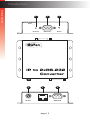
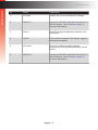
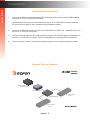
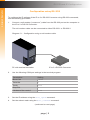
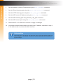
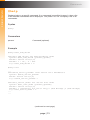
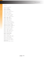
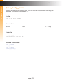
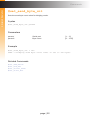
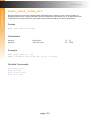
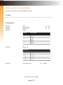
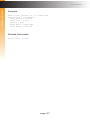
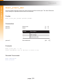
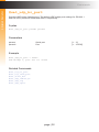
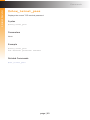
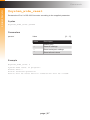
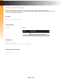
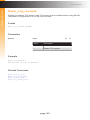
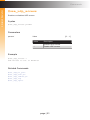
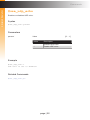
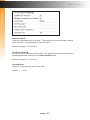
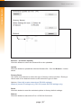
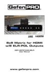
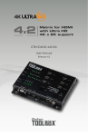
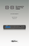
*Preferred
3GSDI
Audio
Embedder
IP to RS-232
Converter
EXT-IP-2-RS2322
User Manual
Release A1
Important Safety Instructions
1.
Read these instructions.
2.
Keep these instructions.
3.
Heed all warnings.
4.
Follow all instructions.
5.
Do not use this product near water.
6.
Clean only with a dry cloth.
7.
Do not block any ventilation openings. Install in accordance with the manufacturer’s
instructions.
8.
Do not install or place this product near any heat sources such as radiators, heat
registers, stoves, or other apparatus (including amplifiers) that produce heat.
9.
Do not defeat the safety purpose of the polarized or grounding-type plug. A polarized
plug has two blades with one wider than the other. A grounding type plug has two
blades and a third grounding prong. The wide blade or the third prong are provided for
your safety. If the provided plug does not fit into your outlet, consult an electrician for
replacement of the obsolete outlet.
10. Protect the power cord from being walked on or pinched particularly at plugs,
convenience receptacles, and the point where they exit from the apparatus.
11. Only use attachments/accessories specified by the manufacturer.
12. To reduce the risk of electric shock and/or damage to this product, never handle or
touch this unit or power cord if your hands are wet or damp. Do not expose this
product to rain or moisture.
13. Unplug this apparatus during lightning storms or when unused for long periods of time.
14. Refer all servicing to qualified service personnel. Servicing is required when the
apparatus has been damaged in any way, such as power-supply cord or plug is
damaged, liquid has been spilled or objects have fallen into the apparatus,
the apparatus has been exposed to rain or moisture, does not operate normally,
or has been dropped.
15. Batteries that may be included with this product and/or accessories should never be
exposed to open flame or excessive heat. Always dispose of used batteries
according to the instructions.
ii
Warranty Information
Gefen warrants the equipment it manufactures to be free from defects in material and
workmanship.
If equipment fails because of such defects and Gefen is notified within two (2) years from
the date of shipment, Gefen will, at its option, repair or replace the equipment, provided
that the equipment has not been subjected to mechanical, electrical, or other abuse or
modifications. Equipment that fails under conditions other than those covered will be
repaired at the current price of parts and labor in effect at the time of repair. Such repairs
are warranted for ninety (90) days from the day of reshipment to the Buyer.
This warranty is in lieu of all other warranties expressed or implied, including without
limitation, any implied warranty or merchantability or fitness for any particular purpose, all of
which are expressly disclaimed.
1.
Proof of sale may be required in order to claim warranty.
2.
Customers outside the US are responsible for shipping charges to and from Gefen.
3.
Copper cables are limited to a 30 day warranty and cables must be in their original
condition.
The information in this manual has been carefully checked and is believed to be accurate.
However, Gefen assumes no responsibility for any inaccuracies that may be contained
in this manual. In no event will Gefen be liable for direct, indirect, special, incidental, or
consequential damages resulting from any defect or omission in this manual, even if
advised of the possibility of such damages. The technical information contained herein
regarding the features and specifications is subject to change without notice.
For the latest warranty coverage information, refer to the Warranty and Return Policy under
the Support section of the Gefen Web site at www.gefen.com.
iii
Contacting Gefen Technical Support
Technical Support
(818) 772-9100
(800) 545-6900
8:00 AM to 5:00 PM Monday - Friday, Pacific Time
Fax
(818) 772-9120
Email
[email protected]
Web
http://www.gefen.com
Mailing Address
Gefen, LLC
c/o Customer Service
20600 Nordhoff St.
Chatsworth, CA 91311
Product Registration
Register your product here: http://www.gefen.com/kvm/Registry/Registration.jsp
iv
Operating Notes
•
When using the IP to 2 x RS-232 Converter for the first time, it is recommended that
the unit be configured using the Gefen Discovery Tool. The Gefen Discovery Tool is
free software that is available from the Support > Downloads section of the Gefen
Web site.
IP to 2 x RS-232 Converter is a trademark of Gefen, LLC.
© 2014 Gefen, LLC. All Rights Reserved. All trademarks are the property of their respective owners.
Gefen, LLC reserves the right to make changes in the hardware, packaging, and any accompanying documentation
without prior written notice.
Pb
This product uses UL or CE listed power supplies.
v
Features and Packing List
Features
•
Allows IP control of two RS-232-enabled devices
•
Supports Telnet and UDP protocols
•
Each of the RS-232 devices can be addressed independently
•
Configurable via Web server interface
•
Independently configurable RS-232 baud rate and line delay for each RS-232 port
•
Gefen Discovery Tool-compatible
•
Field-upgradable firmware via Web server interface
•
Locking power supply connector
•
Surface-mountable
Packing List
The IP to 2 x RS-232 Converter ships with the items listed below. If any of these items are
not present in your box when you first open it, immediately contact your dealer or Gefen.
•
•
•
1 x IP to 2 x RS-232 Converter
1 x 5V DC Power Supply
1 x Quick-Start Guide
vi
vii
Table of Contents
1
Getting Started
Introduction............................................................................................................ 2
Installation.............................................................................................................. 4
Connection Instructions.................................................................................. 4
Sample Wiring Diagram................................................................................. 4
2
Advanced Operation
RS-232 and IP Configuration................................................................................. 8
Configuration using the Gefen Discovery Tool............................................... 8
Configuration using RS-232........................................................................... 9
Commands............................................................................................................11
Web Interface....................................................................................................... 53
Using the built-in Web Interface................................................................... 53
RS-232......................................................................................................... 54
Network tab.................................................................................................. 60
System tab................................................................................................... 66
3Appendix
Default Settings.................................................................................................... 70
RS-232......................................................................................................... 70
Network........................................................................................................ 71
Specifications....................................................................................................... 72
viii
IP to RS-232
Converter
1
Getting Started
Introduction............................................................................................................ 2
Installation.............................................................................................................. 4
Connection Instructions.................................................................................. 4
Sample Wiring Diagram................................................................................. 4
Getting Started
Introduction
1
2
3
IP Reset
RS-232 1
Power
IP Reset
RS-232 1
Power
IP Reset
RS-232 1
Power
EXT-IP-2-RS2322
Gefen
EXT-IP-2-RS2322
Gefen
EXT-IP-2-RS2322
Gefen
IP to 2xRS-232
IP to 2xRS-232
Converter
Converter
IP to 2xRS-232
Converter
4
5
6
5V DC
IP control
RS-232 2
5V DC
IP control
RS-232 2
5V DC
IP control
RS-232 2
page | 2
Getting Started
Introduction
ID
Name
Description
1
IP Reset
Resets the unit to its default IP settings.
2
RS-232 1
Connect an RS-232 cable from this port to an
RS-232 device. See Installation (page 4)
for more information.
3
Power
This LED will glow bright blue when the unit
is powered.
4
5V DC
Connect the included 5V DC power supply to
this power receptacle.
5
IP control
Connect an Ethernet cable between
this jack and an IP-based automation control
device
6
RS-232 2
Connect an RS-232 cable from this port to an
RS-232 device. See Installation (page 4)
for more information.
page | 3
Getting Started
Installation
Connection Instructions
1.
Connect an Ethernet cable between the IP-based control device and the IP control
port on the IP to 2 x RS-232 Converter.
An Ethernet switch can also exist between the IP to 2 x RS-232 Converter and the
IP-based control device (see Sample Wiring Diagram below).
2.
Connect an RS-232 device to each of the RS-232 ports (RS-232 1 and RS-232 2) on
the IP to 2 x RS-232 Converter.
3.
Connect the included 5V DC locking power supply to the 5V DC power receptacle on
the IP to 2 x RS-232 Converter. Do not overtighten the locking power connectors.
4.
Connect the AC power cord from the power supply to an available electrical outlet.
Sample Wiring Diagram
DB-9 CABLE
CAT-5 CABLE
IP-based Automation
Control Device
Ethernet Switch
EXT-IP-2-RS2322
RS-232-enabled
Device
page | 4
RS-232-enabled
Device
EXT-IP-2-RS2322
IP to RS-232
Converter
2
Advanced Operation
RS-232 and IP Configuration................................................................................. 8
Configuration using the Gefen Discovery Tool............................................... 8
Configuration using RS-232........................................................................... 9
Commands............................................................................................................11
Web Interface....................................................................................................... 53
Using the built-in Web Interface................................................................... 53
RS-232......................................................................................................... 54
Network tab.................................................................................................. 60
System tab................................................................................................... 66
page | 7
Advanced Operation
RS-232 and IP Configuration
Configuration using the Gefen Discovery Tool
When using the IP to 2 x RS-232 Converter for the first time, it is recommended that the
unit be configured using the Gefen Discovery Tool. The Gefen Discovery Tool is free
software that is available from the Support > Downloads section of the Gefen Web site.
1.
Download the Gefen Discovery Tool from the Gefen Web site. Extract the files from
the .zip file and follow the installation and configuration instructions in the included
User Manual.
2.
Connect the IP to 2 x RS-232 Converter to the network.
3.
Use the Gefen Discovery Tool to identify the unit on the network.
4.
Refer to the Gefen Discovery Tool User Manual for important information on setting
the IP address, subnet mask, gateway, HTTP listening port, and Telnet listening port.
The following table lists the diefault IP settings for the IP to 2 x RS-232 Converter.
Description
IP Address / Port
Description
IP Address / Port
IP Address
192.168.1.72
UDP Port
23
Subnet
255.255.255.0
Local UDP Port
50007
Gateway
192.168.1.254
Remote UDP IP
192.168.1.255
HTTP Port
80
Remote UDP Port
50008
5.
After the IP settings have been set, make sure to click the Save button in the Gefen
Discovery Tool to save the changes. After saving the changes, click the Reboot button
to reboot the unit.
6.
Launch a Web browser and enter the IP address, that was assigned to the
IP to 2 x RS-232 Converter, in the address bar to access the Web interface.
page | 8
Advanced Operation
RS-232 and IP Configuration
Configuration using RS-232
To configure the IP settings of the IP to 2 x RS-232 Converter using RS-232 commands,
use the following procedure:
1.
Connect a null-modem (“crossover”) cable from the RS-232 port on the computer to
the IP to 2 x RS-232 Converter.
The null-modem cable can be connected to either RS-232 1 or RS-232 2.
Diagram 2.1 - Configuration using a null-modem cable.
PC with terminal-emulation
2.
IP to 2 x RS-232 Converter
Use the following COM port settings in the terminal program:
Description
Setting
Baud rate
19200
Data bits
8
Parity
None
Stop bits
1
Hardware flow control
None
3.
Set the IP address using the #set_ipadd command.
4.
Set the subnet mask using the #set_netmask command.
(continued on next page)
page | 9
Advanced Operation
RS-232 and IP Configuration
5.
Set the gateway (router) IP address using the #set_gateway command.
6.
Set the Telnet listening port using the #set_tcp_term_port command.
7.
Set the HTTP listening port using the #set_http_port command.
8.
Set the UDP remote IP address using the #set_udp_rip command.
9.
Set the UDP listening port using the #set_udp_port command.
10. Set the UDP remote port using the #set_udp_rport command.
11. Reboot the IP to 2 x RS-232 Converter to apply all changes.
12. Launch the desired Web browser and enter the IP address, specified in step 3,
in the address bar to access the Web interface.
Information
Depending upon the network, all related IP, Telnet, and UDP settings will need
to be assigned. If necessary, consult your network administrator to obtain the
proper settings.
page | 10
Advanced Operation
Commands
Command
Description
#help
Displays a list of all available commands
#set_add_delim
Enables or disables option to add delimiter to data
#set_device_descr
Sets the device description
#set_end_del
Sets the end frame delimiter
#set_gateway
Sets the gateway (router) IP address
#set_http_port
Sets the HTTP listening port of the IP to RS-232
Converter
#set_ipadd
Sets the IP address of the IP to RS-232 Converter
#set_netmask
Sets the subnet mask of the IP to RS-232 Converter
#set_send_byte_cnt
Sets the send-byte count value for bridging mode
#set_send_time_out
Sets the time-out value for sending data
#set_serial_descr
Assigns a description to the specified RS-232 port
#set_serial_mode
Sets the serial mode (TCP, UDP, or Terminal)
#set_serial_params
Assigns the settings to the specified RS-232 port
#set_start_del
Sets the Start Frame delimiter
#set_tcp_br_port
Sets the TCP bridge listening port
#set_tcp_term_port
Sets the TCP terminal listening port
#set_telnet_pass
Sets the TCP terminal password
#set_udp_br_port
Sets the UDP bridge listening port
#set_udp_echo_br
Enables or disables UDP bridge echo
#set_udp_port
Sets the UDP listening port
#set_udp_remote_br
Assigns the UDP bridge settings for the specified
RS-232 port
#set_udp_rip
Sets the remote UDP IP address
#set_udp_rport
Sets the UDP remote port
#show_del_prms
Dusplays the current delimiter parameters for the
specified serial port
#show_device_descr
Displays the device description
#show_ipconfig
Displays the current TCP/IP and UDP settings of the IP
to 2 x RS-232 Converter
#show_me
Enables or disables the flashing of the LED on the
device
#show_serial_descr
Displays the current description of the specified RS-232
port
#show_serial_mode
Displays the mode of the specified RS-232 port
(continued on next page)
page | 11
Advanced Operation
Commands
Command
Description
#show_serial_params
Displays the settings of the specified RS-232 port
#show_telnet_pass
Displays the current TCP terminal password
#show_ver_data
Displays the firmware and hardware version of the IP to
RS-232 Converter
#system_wide_reset
Restarts the IP to 2 x RS-232 Converter according to
the supplied parameter
#use_discovery
Enables or disables discovery mode
#use_tcp_access
Enables or disables TCP access mode
#use_tcp_term_pass
Enables or disables the password prompt at the
beginning of a Telnet session
#use_udp_access
Enables or disables UDP access
#use_udp_echo
Enables or disables UDP echo
page | 12
Advanced Operation
Commands
#help
Displays help on a specific command. If no command is specified (param1), then a list
of all available commands will be displayed. Set param1 to “full” to display a list of all
commands.
Syntax
#help
Parameters
param1
Command (optional)
Example
#help #set_add_delim
Cmd #set_add_delim: Set Add delimiter mode
Syntax: #set_add_delim [param1][pram2]
Param1: Serial Port(1,2)
Param2: 1 - On , 0 - Off
e.g: #set_add_delim 1 0
#help full
...
Cmd #show_serial_params: Show Serial Port Parameters
Syntax: #show_serial_params
Param: Serial Port(1,2)
e.g: #show_serial_params 1
Cmd #set_serial_mode: Set Serial Port mode
Syntax: #set_uart_mode [param1][param2]
Param1: Serial Port(1,2)
Param2: 1 (Terminal) for Port1 only,2 (TCP Bridge),3 (UDP Bridge)
e.g: #set_serial_mode 1 2
...
...
(continued on next page)
page | 13
Advanced Operation
Commands
#help
#show_ipconfig
#set_ipadd
#set_netmask
#set_gateway
#set_http_port
#set_tcp_term_port
#set_udp_port
#show_ver_data
#show_telnet_pass
#set_telnet_pass
#use_tcp_term_pass
#set_udp_rip
#set_udp_rport
#use_udp_access
#use_udp_echo
#use_tcp_access
#set_serial_params
#show_serial_params
#set_serial_mode
#show_serial_mode
#show_serial_connect
#set_serial_descr
#show_serial_descr
#set_tcp_br_port
#set_udp_br_port
#set_udp_remote_br
#set_udp_echo_br
#use_discovery
#set_add_delim
#set_start_del
#set_end_del
#set_send_time_out
#set_send_byte_cnt
#show_del_prms
#set_device_descr
#show_device_descr
#show_me
#system_wide_reset
page | 14
Advanced Operation
Commands
#set_add_delim
Enables or disables the option to include a delimiter as part of the data sent to the control
system.
Syntax
#set_add_delim param1 param2
Parameters
param1
param2
Value[1 ... 2]
State
[0 ... 1]
Value
Description
0
Off
1
On
Example
#set_add_delim 1
Add delimiter mode to ON
Related Commands
#set_end_del
#set_start_del
page | 15
Advanced Operation
Commands
#set_device_descr
Sets the device description. The device description cannot exceed 30 characters in length
Syntax
#set_device_descr param1
Parameters
param1
Description
Example
#set_device_descr LivingRoom_Bridge2
Device Description changed to: LivingRoom_Bridge2
Related Commands
#show_device_descr
page | 16
[30 chars max.]
Advanced Operation
Commands
#set_end_del
Sets the end-delimiter mode and value for the specified serial port. The End Delimiter value
must be specified in hexadecimal. Before executing this command, the Start Delimiter must
be set, using the #set_start_del command.
Syntax
#set_end_del param1 param2 param3
Parameters
param1
param2
param3
Serial port
State
Value
Description
0
Off
1
On
End delimiter
Example
#set_end_del 1 1 ba
End delimiter set to ON with a value of ba
Related Commands
#set_add_delim
#set_start_del
page | 17
[1 ... 2]
[0 ... 1]
[00 ... FF]
Advanced Operation
Commands
#set_gateway
Sets the gateway address. The gateway must be typed using dot-decimal notation.
The matrix must be rebooted after executing this command. The default gateway is
192.168.1.1.
Syntax
#sgateway param1
Parameters
param1
Gateway
Example
#set_gateway 10.5.64.1
New IP Gateway set to: 10.5.64.1
Related Commands
#set_add_delim
#set_ipadd
#set_netmask
#show_ipconfig
page | 18
Advanced Operation
Commands
#set_http_port
Specifies the Web server listening port. The unit must be rebooted after executing this
command. The default port setting is 80.
Syntax
#set_http_port param1
Parameters
param1
Port[1 ... 1024]
Example
#set_http_port 82
New HTTP port set to: 82
Related Commands
#set_gateway
#set_ipadd
#set_netmask
#show_ipconfig
page | 19
Advanced Operation
Commands
#set_ipadd
Specifies the IP address of the IP to 2 x RS-232 Converter. The IP address must be
specified using dot-decimal notation. The unit must be rebooted after executing this
command. The default IP address is 192.168.1.72.
Syntax
#set_ipadd param1
Parameters
param1
IP address
Example
#set_ipadd 10.5.64.187
New IP set to: 10.5.64.187
Related Commands
#set_gateway
#set_http_port
#set_end_del
#show_ipconfig
page | 20
Advanced Operation
Commands
#set_netmask
Sets the subnet mask. The subnet mask must be entered using dot-decimal notation.
The unit must be rebooted after executing this command. The default net mask is
255.255.255.0.
Syntax
#snetmask param1
Parameters
param1
Net mask
Example
#snetmask 255.255.0.0
New IP Mask set to: 255.255.0.0
Related Commands
#set_gateway
#set_ipadd
#set_http_port
#show_ipconfig
page | 21
Advanced Operation
Commands
#set_send_byte_cnt
Sets the send-byte count value for bridging mode.
Syntax
#set_send_byte_cnt param1
Parameters
param1
param2
Serial port
Byte count
[1 ... 2]
[0 ... 255]
Example
#set_send_byte_cnt 1 100
UART 1 bridging send byte count limit is set to 100 bytes
Related Commands
#set_add_delim
#set_end_del
#set_serial_mode
#set_start_del
page | 22
Advanced Operation
Commands
#set_send_time_out
Sets the time-out value for sending data collected from a device to the control system in
Bridging Mode when a Start Delimiter and End Delimiter have been set. If no data has been
collected for the specified time, the data is sent without waiting for the End Delimiter.
Syntax
#set_send_time_out param1
Parameters
param1
param2
Serial port
Time out (ms)
Example
#set_send_time_out 1 30
UART 1 bridging sent Time Out is set to 30 ms
Related Commands
#set_add_delim
#set_end_del
#set_serial_mode
#set_start_del
page | 23
[1 ... 2]
[0 ... 255]
Advanced Operation
Commands
#set_serial_descr
Assigns a descriptor to the specified serial port. The serial port description cannot exceed
20 characters in length. The default description is None.
Syntax
#set_serial_descr param1 param2
Parameters
param1
param2
Port[1 ... 2]
Description
[20 chars max.]
Example
#set_serial_descr 1 DVD_Ctrl
Serial port 1 Description: DVD_Ctrl
Related Commands
#show_serial_descr
page | 24
Advanced Operation
Commands
#set_serial_mode
Sets the mode of the specified serial port. The default mode for all serial ports (1 - 2)
is TCP Bridge mode.
Syntax
#set_serial_mode param1 param2
Parameters
param1
param2
Port[1 ... 2]
State
[1 ... 3]
Mode
Description
1
TCP bridge
2
UDP bridge
3
Terminal mode
Example
#set_serial_mode 1 2
Serial port 1 working mode is: TCP Bridge Mode
Related Commands
#show_serial_mode
page | 25
Advanced Operation
Commands
#set_serial_params
Assigns the settings to the specified serial port.
Syntax
#set_serial_params param1 param2 param3 param4 param5 param6
Parameters
param1
param2
param3
param4
param5
Port[1 ... 3]
Word length
[5 ... 8]
Stop bits
[1 ... 2]
Parity
Parity
Description
n
None
e
Even
o
Odd
m
Mark
s
Space
Baud rate
Baud rate
110
4800
600
14400
300
1200
2400
param6
9600
19200
28800
Line delay (ms)
(continued on next page)
page | 26
[0 ... 10000]
Advanced Operation
Commands
Example
#set_serial_params 1 8 1 N 19200 1000
Serial port 1 parameters:
Word length = 8 bits
Stop bits = 1 bit
Parity = None
Baud Rate = 19200 Bps
Line Delay = 1000 ms
Related Commands
#show_serial_params
page | 27
Advanced Operation
Commands
#set_start_del
Sets the Start Delimiter mode and value for the specified serial port. The Start Delimiter
must always be specified before the End Delimiter.
Syntax
#set_start_del param1 param2 param3
Parameters
param1
param2
param3
Serial port
State
Mode
Description
1
TCP bridge
2
UDP bridge
3
Terminal mode
Start delimiter
Example
#set_start_del 1 1 a0
Start delimiter set to ON with a value of a0
Related Commands
#set_add_delim
#set_end_del
page | 28
[1 ... 2]
[0 ... 1]
[00 ... FF]
Advanced Operation
Commands
#set_tcp_br_port
Sets the TCP bridge listening port for the specified serial port. The default port settings for
RS-232 1 and RS-232 2 ports are 49200 and 49201, respectively.
Syntax
#set_tcp_br_port param1 param2
Parameters
param1
param2
Serial port
TCP port
Example
#set_tcp_br_port 1 49200
TCP Bridge 1, port set to: 49200
Related Commands
#set_tcp_term_port
#set_udp_br_port
page | 29
[1 ... 2]
[1 ... 65535]
Advanced Operation
Commands
#set_tcp_term_port
Sets the TCP terminal listening port. The default port settings is 23.
Syntax
#set_tcp_term_port param1
Parameters
param1
TCP port
Example
#set_tcp_term_port 23
New TCP Terminal port set to: 23
Related Commands
#set_tcp_br_port
#set_udp_br_port
page | 30
[1 ... 65535]
Advanced Operation
Commands
#set_telnet_pass
Sets the TCP Terminal password. The password cannot exceed 20 characters in length.
param3 is used to verify the new password. The default password is Admin.
Syntax
#set_telnet_pass param1 param2 param3
Parameters
param1
param2
param3
Old password
New password
New password
Example
#set_telnet_pass Admin b055man b055man
TCP Terminal password updated to: b055man
Related Commands
#set_tcp_br_port
page | 31
[20 chars max.]
[20 chars max.]
[20 chars max.]
Advanced Operation
Commands
#set_udp_br_port
Sets the UDP bridge listening port. The default UDP bridge port settings for RS-232 1
and RS-232 2 ports are 50200 and 50201, respectively.
Syntax
#set_udp_br_port param1 param2
Parameters
param1
param2
Serial port
[1 ... 2]
Port[1 ... 65535]
Example
#set_udp_br_port 1 50200
UDP Bridge 1, port set to: 50200
Related Commands
#set_tcp_br_port
#set_tcp_term_port
#set_start_del
#set_udp_remote_br
#set_udp_rip
#set_udp_rport
page | 32
Advanced Operation
Commands
#set_udp_echo_br
Enables or disables UDP bridge echo.
Syntax
#set_udp_echo_br param1 param2
Parameters
param1
param2
Serial port
State
State
Description
0
Disabled
1
Enabled
Example
#set_udp_echo_br 1 1
The echo of UDP Bridge port 1 is enabled
Related Commands
#set_udp_br_port
#set_udp_remote_br
#set_udp_rip
#set_udp_rport
page | 33
[1 ... 2]
[0 ... 1]
Advanced Operation
Commands
#set_udp_port
Sets the UDP server listening port
Syntax
#set_udp_port param1
Parameters
param1
Serial port
Example
#set_udp_port 50007
New UDP server port set to: 50007
Related Commands
#set_udp_br_port
#set_udp_remote_br
#set_udp_echo_br
#set_udp_rip
#set_udp_rport
page | 34
[1 ... 65535]
Advanced Operation
Commands
#set_udp_remote_br
Assigns the UDP Bridge settings for the specified serial port. param2 must be entered in
dot-decimal notation.
Syntax
#set_udp_remote_br param1 param2 param3
Parameters
param1
param2
param3
Serial port
Address
Remote port
[1 ... 2]
[1 ... 65535]
Example
#set_udp_remote_br 1 192.168.1.70 51000
Remote UDP bridge 1 set to: IP=192.168.1.70 Port=51000
Related Commands
#set_udp_port
#set_udp_br_port
#set_udp_echo_br
#set_udp_rip
#set_udp_rport
page | 35
Advanced Operation
Commands
#set_udp_rip
Sets the remote UDP IP address. The IP address must be entered using dot-decimal
notation. Each digit can range between 0 and 255.
Syntax
#set_udp_rip param1
Parameters
param1
IP address
Example
#set_udp_rip 192.168.1.205
New Remote UDP IP set to: 192.168.1.205
Related Commands
#set_udp_br_port
#set_udp_echo_br
#set_udp_remote_br
#set_udp_echo_br
page | 36
Advanced Operation
Commands
#set_udp_rport
Sets the remote UDP listening port. The default port settings is 50008.
Syntax
#set_udp_rport param1
Parameters
param1
Port[1 ... 65535]
Example
#set_udp_rport 50006
New UDP Remote port set to: 50006
Related Commands
#set_udp_br_port
#set_udp_echo_br
#set_udp_remote_br
#set_udp_rip
page | 37
Advanced Operation
Commands
#show_del_prms
Displays the current delimiter parameters for the specified serial port.
Syntax
#show_del_prms param1
Parameters
param1
Port[1 ... 2]
Example
#show_del_prms 1
Delimiter Param’s in bridge mode, UART 1
Line Delay = 1000ms
Time To Force Send = 30ms
Count Byte To Force Send = 100
Add Delimiters In Data = False
Use Start Delimiter = False
Start Delimiter Size = 1
Start Delimiter Value = A0
Use End Delimiter = True
End Delimiter Size = 1
Start Delimiter Value = B0
Related Commands
#set_add_delim
#set_end_del
#set_send_byte_cnt
#set_send_time_out
#set_serial_params
#set_start_del
page | 38
Advanced Operation
Commands
#show_device_descr
Displays the device description.
Syntax
#show_device_descr
Parameters
None
Example
#show_device_descr
Device Description: IP_BRIDGE
Related Commands
#set_device_descr
page | 39
Advanced Operation
Commands
#show_ipconfig
Displays the current TCP/IP and UDP settings.
Syntax
#show_ipconfig
Parameters
None
Example
#show_ipconfig
--------- IP to 2 x RS-232 Converter settings --------MAC addr = 00:1C:91:01:0F:FF
IP addr = 10.5.64.254
Net Mask = 255.255.255.0
Gateway = 192.168.1.254
Web Server Port = 80
TCP Terminal Server Port = 23
TCP Terminal Access = Enabled
TCP Terminal password at login is set to OFF
UDP Access = Disabled
UDP Server Port = 50007
Enable UDP Echo = Disabled
UDP Remote IP = 192.168.1.80
UDP Remote Port = 50008
TCP Bridge 1 Port = 49200
TCP Bridge 2 Port = 49201
UDP Local Bridge 1 Port = 50200
UDP Remote Bridge 1 IP = 192.168.1.180, Port = 50000
UDP Remote Bridge 1 Echo = Disabled
UDP Local Bridge 2 Port = 50201
UDP Remote Bridge 2 IP = 192.168.1.181, Port = 50001
UDP Remote Bridge 2 Echo = Disabled
Discovery Mode: Enabled
Related Commands
#set_gateway
#set_http_port
#set_ipadd
#set_netmask
#set_tcp_br_port
#set_tcp_term_port
#set_udp_br_port
#set_udp_echo_br
#set_udp_port
#set_udp_remote_br
#set_udp_rip
#set_udp_rport
page | 40
#use_discovery
#use_tcp_access
#use_tcp_term_pass
#use_udp_access
#use_udp_echo
Advanced Operation
Commands
#show_me
Enables or disables the flashing of the LED on the device. When enabled, the LED
indicator will flash red and blue. The default setting is disabled.
Syntax
#show_me param1
Parameters
param1
State
State
Description
0
Disabled
1
Enabled
Example
#show_me 1
Show me is Enabled
Related Commands
#use_discovery
page | 41
Advanced Operation
Commands
#show_serial_descr
Displays the description of the specified serial port.
Syntax
#show_serial_descr param1
Parameters
param1
Port[1 ... 2]
Example
#show_serial_descr 1
Serial port 1 Description:
DVD_Ctrl
Related Commands
#set_serial_descr
page | 42
Advanced Operation
Commands
#show_serial_mode
Displays the mode of the specified serial port.
Syntax
#show_serial_mode param1
Parameters
param1
Port[1 ... 2]
Example
#show_serial_mode 1
Serial port 1 working mode is: TCP Bridge Mode
Related Commands
#set_serial_mode
page | 43
Advanced Operation
Commands
#show_serial_params
Displays the current settings of the specified serial port.
Syntax
#show_serial_params param1
Parameters
param1
Port[1 ... 2]
Example
#show_serial_params 1
Serial port 1 parameters:
Word length = 8 bits
Stop bits = 1 bit
Parity = None
Baud Rate = 19200 Bps
Line Delay = 1000 ms
Related Commands
#set_serial_params
page | 44
Advanced Operation
Commands
#show_telnet_pass
Displays the current TCP terminal password.
Syntax
#show_telnet_pass
Parameters
None
Example
#show_telnet_pass
TCP Terminal password: b055man
Related Commands
#set_telnet_pass
page | 45
Advanced Operation
Commands
#show_ver_data
Displays the current software and hardware version.
Syntax
#show_ver_data
Parameters
None
Example
#show_ver_data
Firmware version 1.48
Release date: May 12 2014
Release time: 14:09:37
page | 46
Advanced Operation
Commands
#system_wide_reset
Restarts the IP to 2 x RS-232 Converter according to the supplied parameter.
Syntax
#system_wide_reset param1
Parameters
param1
Value[0 ... 3]
Value
Description
0
Reboot only
1
Reset IP settings
2
Reset serial port settings
3
Reset all and reboot
Example
#system_wide_reset 3
System
Please
Finish
Device
wide reset in progress.
wait...
selected operation.
will be reset and all connections will be closed.
page | 47
Advanced Operation
Commands
#use_discovery
Enables or disables discovery access mode. If this mode is disabled, then the
IP to 2 x RS-232 Converter will not be discoverable when using the Gefen Discovery Tool.
The default setting is enabled.
Syntax
#use_discovery param1
Parameters
param1
State
State
Description
0
Discovery access disabled
1
Discovery access enabled
Example
#use_discovery 1
Discovery Access is set to Enabled
Related Commands
#show_me
page | 48
Advanced Operation
Commands
#use_tcp_access
Enables or disables TCP access mode. This mode must be enabled before using RS-232
command to configure the IP to 2 x RS-232 Converter.
Syntax
#use_tcp_access param1
Parameters
param1
Value[0 ... 1]
Value
Description
0
Disable TCP access
1
Enable TCP access
Example
#use_tcp_access 1
TCP Access is set to Enabled
Related Commands
#set_tcp_br_port
#set_tcp_term_port
#set_telnet_pass
#use_tcp_term_pass
page | 49
Advanced Operation
Commands
#use_tcp_term_pass
Enables or disables the use of the password during terminal sessions.
Syntax
#use_tcp_term_pass param1
Parameters
param1
Value[0 ... 1]
Value
Description
0
Do not use password
1
Require password
Example
#use_tcp_term_pass 1
TCP Terminal password at login is set to ON
Related Commands
#set_tcp_br_port
#set_tcp_term_port
#set_telnet_pass
#use_discovery
page | 50
Advanced Operation
Commands
#use_udp_access
Enables or disables UDP access.
Syntax
#use_udp_access param1
Parameters
param1
Value[0 ... 1]
Value
Description
0
Disable UDP access
1
Enable UDP access
Example
#use_udp_access 1
UDP Access is set to Enabled
Related Commands
#set_udp_br_port
#set_udp_echo_br
#set_udp_remote_br
#set_udp_rip
#set_udp_rport
page | 51
Advanced Operation
Commands
#use_udp_echo
Enables or disables UDP echo.
Syntax
#use_udp_echo param1
Parameters
param1
Value[0 ... 1]
Value
Description
0
Disable UDP echo
1
Enable UDP echo
Example
#use_udp_echo 1
UDP echo is set to Enabled
Related Commands
#set_udp_echo_br
page | 52
Advanced Operation
Web Interface
Using the built-in Web Interface
Access the built-in Web interface by entering the IP address of the IP to 2 x RS-232
Converter that was specified in step 3 under Configuration using RS-232 (page 9).
The built-in Web interface is divided into three pages: RS-232, Network, and System.
Each main page is represented by a tab at the top of the screen. The RS-232 page will
always be displayed first.
Help
Click the Help button to display context-sensitive help for the current
page. The help window can be moved to any position within the Web
browser window.
page | 53
Advanced Operation
Web Interface
RS-232
Select RS-232 Port
Select the RS-232 port from the drop-down list.
Options: 1, 2
Description
Enter a description for the device that is connected to the selected RS-232 port.
RS-232 Mode
Select the desired mode from the drop-down list.
Options: TCP Bridge, UDP Bridge, Terminal
page | 54
Advanced Operation
Web Interface
Baud Rate
Select the baud rate used by the RS-232 device from this drop-down list.
Options: 110, 300, 600, 1200, 2400, 4800, 9600, 14400, 19200, 28800
Data Bits
Select the number of data bits in each character from this drop-down list.
For most applications, 8 data bits should be selected. 9 data bits are rarely used.
Options: 8, 9
Parity
Select the parity bit type from this drop-down list.
Options: None, Even, Even Stick, Odd, Odd Stick
Stop Bits
Select the number of stop bits from this drop-down list.
Options: 1, 2
page | 55
Advanced Operation
Web Interface
Line Delay (ms)
Enter the line delay in this field.
Range: 0 ... 10000
Force Send (ms)
If no data is received from the controlled device within the specified time interval,
send the collected data to the control system.
Range: 0 ... 30
Force Send (bytes)
If the specified number of bytes is received from the controlled device, send the
collected data to the control system.
Range: 0 ... 255
page | 56
Advanced Operation
Web Interface
Add Delimiters to data sent
Include the delimiter characters in the data sent to the control system. Check the
Add box to enable this feature.
Options: Enable (checked), Disable (unchecked)
Use Start Delimiter
Includes the Start Frame Delimiter, used at the end of the preamble of an
Ethernet frame.
Options: Enable (checked), Disable (unchecked)
Start Delimiter Value
This value can be up to three ASCII characters (3 bytes), in length. The value
must be entered in hexadecimal (e.g 0D0A, which is CR + LF). The Start
(Frame) Delimiter Value is used by some control systems to filter incoming data.
Contact Gefen Technical Support for details if you need to use them.
Range: 00 ... FF (“wildcard” characters, such as **, are acceptable)
Use End Delimiter
Includes the End Frame Delimiter, used at the end of a transmission frame.
Options: Enable (checked), Disable (unchecked)
page | 57
Advanced Operation
Web Interface
End Delimiter Value
This value can be up to three ASCII characters (3 bytes), in length. The value
must be entered in hexadecimal
Range: 00 ... FF (“wildcard” characters, such as **, are acceptable)
TCP Port
Enter the TCP port in this field.
Range: 0 ... 65535
UDP Local Port
Enter the UPD local port in this field.
Range: 1024 ... 65535
page | 58
Advanced Operation
Web Interface
Destination IP
Enter the destination (where the data will be sent) IP address in this field.
Range (per byte): 0 ... 255
Destination Port
Enter the destination port in this field.
Range: 1024 ... 65535
UDP Echo
Useful in troubleshooting and measuring response times and end-to-end
connectivity.
Options: Enable (checked), Disable (unchecked)
Set Defaults
Click this button to reset RS-232 settings to their default values.
Save
Click this button to save any changes.
page | 59
Advanced Operation
Web Interface
Network tab
MAC Address
The MAC address of the IP to RS-232 Converter. The MAC address cannot be
changed.
Mode
Select the network mode from the drop-down list.
Options: Static, DHCP
IP Address
Enter the IP address of the IP to 2 x RS-232 Converter.
Range (per byte): 0 ... 255
Subnet
Enter the subnet mask of the IP to 2 x RS-232 Converter.
Range (per byte): 0 ... 255
page | 60
Advanced Operation
Web Interface
Gateway
The gateway (router) IP address to with the IP to 2 x RS-232 Converter is
connected.
Range (per byte): 0 ... 255
HTTP Port
Select the network mode from the drop-down list.
Range (per byte): 1 ... 1024
page | 61
Advanced Operation
Web Interface
Enable TCP Access
Enables or disables TCP access.
Options: Enable (checked), Disable (unckecked)
Require Password on Connect
Forces password prompt for Telnet sessions.
Options: Enable (checked), Disable (unckecked)
User Name
Displays the user name for TCP sessions. The user name cannot be changed.
Old Password
Type the current (old) password in this field. The password is automatically
masked when entered. The password is case-sensitive. The default password
is Admin.
Maximum length: 8 characters
page | 62
Advanced Operation
Web Interface
New Password
Type the new password in this field. The password is automatically masked
when entered. The password is case-sensitive.
Maximum length: 8 characters
Confirm Password
Re-type the new password in this field. The password must match the same
password that was entered in the New Password field.
Maximum length: 8 characters
Terminal Port
Type the Telnet listening port in this field.
Range: 1 ... 1024
page | 63
Advanced Operation
Web Interface
Enable UDP Access
Enables or disables UDP access.
Options: Enable (checked), Disable (unckecked)
UDP Port
Sets the UDP port.
Range: 1 ... 1024
Enable UDP Echo
Enables or disables UDP echo.
Options: Enable (checked), Disable (unckecked)
page | 64
Advanced Operation
Web Interface
Destination UDP IP Address
Enter the remote UDP IP address in this field.
Range (per byte): 0 ... 255
Destination UDP Port
Type the remote UDP port in this field.
Range: 1 ... 1024
Enable Discovery
Enables or disables discovery mode. This feature must be enabled in order for
the Gefen Discovery Tool to detect the unit on a network.
Options: Enable (checked), Disable (unckecked)
page | 65
Advanced Operation
Web Interface
System tab
Download (Download Current Configuration)
Saves the current configuration of the IP to 2 x RS-232 Converter to a file.
Browse... (Restore Configuration)
Selects the configuration file to load. See the Download button, above.
Restore
Click this button to upload the selected configuration file to the IP to 2 x RS-232
Converter.
page | 66
Advanced Operation
Web Interface
Browse... (Firmware Update)
Click this button to select the firmware file to be uploaded.
Update
Click this button to upload the selected firmware file. See the Browse... button,
above.
Factory Reset
Use these check boxes to select the type of factory-reset to perform. Placing a
check mark in the desired check box will select the type of reset:
Options: Select All (resets network and RS-232 settings),
Network (resets IP settings only), RS-232 (resets RS-232 settings only)
Reset
Click this button to reset the selected options to factory-default settings.
Reboot
Click this button to reboot the IP to 2 x RS-232 Converter.
page | 67
IP to RS-232
Converter
3Appendix
Default Settings.................................................................................................... 70
RS-232......................................................................................................... 70
Network........................................................................................................ 71
Specifications....................................................................................................... 72
Appendix
Default Settings
The following table lists the default setting of the IP to 2 x RS-232 Converter, as displayed
under the built-in Web interface.
RS-232
RS-232 Settings
Select RS-232 Port
•
1
Description
•
None
RS-232 Mode
•
TCP Bridge
Baud Rate
•
19200
Data Bits
•
8
Parity
•
None
Stop Bits
•
1
Line Delay (ms)
•
0
Force Send (ms)
•
30
Force Send (bytes)
•
100
Add Delimiters to data sent
•
Disabled
Use Start Delimiter
•
Disabled
Start Delimiter Value
•
0
Use End Delimiter
•
Disabled
End Delimiter Value
•
0
TCP Port
•
49200
UDP Local Port
•
50200
Destination IP
•
192.168.1.180
Destination Port
•
50000
UDP Echo
•
Disabled
Bridging Settings
UDP Echo
page | 70
Appendix
Default Settings
Network
IP Settings
MAC Address
•
Device-dependent (cannot be changed)
Mode
•
Static
IP Address
•
192.168.1.72
Subnet
•
255.255.255.0
Gateway
•
192.168.1.254
HTTP Port
•
80
Enable TCP Access
•
Disabled
Require Password on Connect
•
Disabled
User Name
•
Admin (cannot be changed)
Old Password
•
(default password is “Admin”)
New Password
•
---
Confirm New Password
•
---
Terminal Port
•
23
Enable UDP Access
•
Disabled
UDP Port
•
50007
Enable UDP Echo
•
Disabled
Destination UDP IP Address
•
192.168.1.80
Destination UDP Port
•
50008
Enable Discovery
•
Enabled
TCP / Telnet Settings
UDP Settings
page | 71
Appendix
Specifications
Connectors, Indicators, and Controls
RS-232
•
2 x DB-9, male
IP control
•
1 x RJ-45
Power
•
1 x 5V DC, locking
Power indicator
•
1 x LED, blue
IP Reset button
•
1 x Tact-type, recessed
Power
•
5V DC
Power consumption
•
1W (max.)
Dimensions (W x H x D)
•
4.3” x 1” x 3.4”
(110mm x 26mm x 86mm)
Unit Weight
•
0.35 lbs. (0.16 kg)
Operational
Physical
page | 72
*Preferred
Stretch it. Switch it. Split it. Gefen’s got it. ®
20600 Nordhoff St., Chatsworth CA 91311
1-800-545-6900 818-772-9100 fax: 818-772-9120
www.gefen.com [email protected]