1
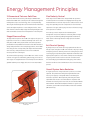
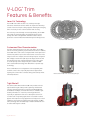
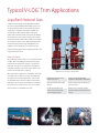
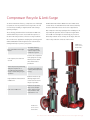
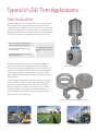
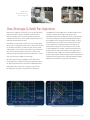
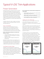
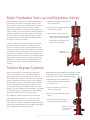
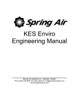
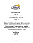
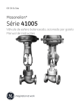
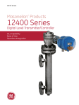
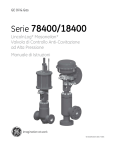
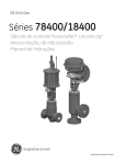
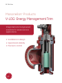
GE Oil & Gas
Masoneilan* Products
V-LOG* Energy Management Trim
Integrated smart engineered
solutions for severe service
applications
• Scalable trim design
• Operational stability
• Precision control
V-LOG* Trim Technology
GE Oil & Gas offers a broad portfolio of Masoneilan* products
consisting of general service and severe service control
valves, actuators, pressure regulators, and valve-mounted
smart instrumentation and accessories – all supported by
an integrated network of sales offices. The breadth of our
offerings enables us to help customers meet the demanding
requirements of process control applications.
Masoneilan* valve solutions, which include leading designs
such as the LincolnLog* liquid letdown control valve, range
from regulators to customized solutions, including the patented
V-LOG* labyrinth trim technology. We offer custom-tailored
solutions configured for control performance, shut-off reliability
and life-cycle cost- effectiveness. Leading product technology
coupled with application expertise are the keys to our ability to
meet customers’ specifications.
Cost-Effective Engineered Solutions
We offer leading microprocessor-based field instrumentation
technology. Award-winning HART communicating SVI* and
FVP* digital positioners help improve your asset’s effectiveness,
resulting in higher returns on investment. By using patented
tuning algorithms that optimize valve control performance, our
digital positioners deliver improved process yields and lower
maintenance cost.
Innovative V-LOG* Design
Our valve design innovation is at the foundation of our
extensive portfolio of field-proven severe service products
configured for the most challenging applications. GE Oil & Gas’
Masoneilan* products have long been benchmarks for severe
service innovation in industries such as power generation,
oil and gas production and liquefied natural gas (LNG).
These industries present many of the toughest control valve
applications, particularly those involving large mass flow rate
and high differential pressure such as compressor anti-surge,
high pressure vents and turbine bypass.
Severe service applications present technical challenges
associated with the high energy of the flow stream. V-LOG*
Energy Management trim meets these challenges, including
the energy-related issues of noise and vibration, and stringent
demands for control performance.
Benefiting from a very scalable trim design architecture,
V-LOG* trim offers a customized solution for a broad set of
severe compressible fluid and liquid applications. Each V-LOG*
trim solution is designed to meet customer requirements
including tight shutoff, fast opening speeds, operational
stability, and precision control over a wide range of operating
conditions.
Flexibility is built into each of GE Oil & Gas’ digital
instrumentation offerings. SVI* II AP and FVP* valve positioners
mount on any control valve actuator and interface effectively
with HART and Foundation Fieldbus distributed control
schemes, respectively (since SVI* is only Hart and FVP* is only
FF).
You can further increase flexibility and functionality with GE’s
smart instrument companion software such as ValVue*, a tool
that monitors real-time device status. In addition, ValvKeep*
valve database management and AMS Snap-on™ asset
management software provide a comprehensive view into
valve asset maintenance history and performance trends.
These software support tools, in conjunction with the advanced
diagnostic capabilities of smart devices, help significantly
reduce operating costs.
2 | GE Oil & Gas
V-LOG* Trim Stack
Energy Management Principles
3-Dimensional Tortuous Path Flow
Fluid Velocity Control
The three-dimensional tortuous path design of GE Oil & Gas’
Masoneilan V-LOG* trim controls pressure reduction through the
management of process fluid energy. This is accomplished by
directing the fluid through discrete flow channels which alternate
across two adjacent planes to create a labyrinth effect. These
flow channels contain multiple stages defined by 90 degree turns
with intermediate contractions and expansions in the flow path.
Each stage of the V-LOG* trim is designed with an expansion
in flow area, which is essential for managing fluid velocity that
would otherwise increase as the pressure is reduced across each
stage. The expanding area can compensate for the volumetric
expansion of the gas, reducing any increase in the kinetic energy
as the pressure is reduced.
Staged Pressure Drop
The labyrinth flow path of the V-LOG* trim subjects the gas to a
high level of friction as it is redirected through each turn in the
flow path. V-LOG* trim’s patented flow contractions produce
predictable and repeatable flow resistance that differentiates its
design and performance from competing products. The V-LOG*
trim’s design offers a unique flow path shape which maximizes
valve efficiency and performance versus more traditional
tortuous path trim technologies.
The enhanced flow geometry of the V-LOG* trim creates a series
of kinetic energy losses followed by partial energy recoveries at
each stage. The staged reduction of the fluid pressure makes the
gradual letdown process highly effective for noise attenuation.
Trim velocity control is important for maintaining low
aerodynamic noise levels within the valve body and trim. High
velocity trim exit flow will yield high magnitude sound waves,
which lead to valve body vibration in high-pressure letdown
applications.
Exit Flow Jet Spacing
By design, the process fluid is precisely separated into discrete
flow jets upon exiting the V-LOG* trim channels. The proper sizing
and spacing of these channels prevents the exiting flow jets from
reconverging, thus producing lower amplitude sound waves with
higher peak frequencies. These lower sound pressure and higher
frequency waves result in lower acoustical coincidence with
the surrounding system and downstream piping. This reduces
both the overall noise level and vibration effect of the throttling
process.
Overall System Noise Reduction
As a gas experiences a large reduction in pressure, its volume
expands. This phenomenon will yield a higher downstream
velocity if the piping is configured without considering this
volumetric expansion. Our angle body valve designs feature
expanded outlet areas to accommodate this expansion and
minimize the overall system noise level. (we consider both Outlet
Mach Number and the Outlet Expansion Ratio for system noise
calculation, per the IEC International Noise Prediction Standard
[IEC-60534-8-3]).
The V-LOG* Trim’s Labyrinth
Flow Path
GE’s Masoneilan V-LOG* Energy Management Trim for Severe Service Applications | 3
V-LOG* Trim
Features & Benefits
Laser Cut Technology
The V-LOG* trim’s disks are laser cut, resulting in the tight
tolerances and smooth surfaces which are required for throttling
control. Precision trim-part cutting supports throttling area integrity
that is necessary for fine control resolution and accuracy.
Prior to being secured through vacuum-tight brazing, the V-LOG*
trim’s disks are stacked together and aligned using precision
tooling. Each disk is designed with maximum surface area to
promote a secure bond between disks during the brazing process.
Laser Cut V-LOG* Trim Disks
Customized Flow Characterization
The laser manufacturing process gives each disk in the V-LOG*
trim the necessary geometry to provide desired control. In addition,
the V-LOG* trim’s stack can be configured with tiered capacities in
each disk to produce specific flow characteristic across the entire
range of travel. For example, the stack design may be configured
with a highly resistant flow path (up to 40 stages) at low lift and
then progressively less resistant flow paths as the valve opens
to its full capacity. Some designs may also combine V-LOG*
trim’s stacked disk technology with drilled-hole or ported-cage
technology.
These combination trim configurations offer rangeability with
excellent control. This is especially important for applications
requiring the control valve to throttle during plant startup and at
full load production.
Characterized V-LOG* Trim & Ported Cage Design
Tight Shutoff
The full line of GE’s Masoneilan* V-LOG* trim products achieve
tight shutoff through seating-surface geometry and material
selection. Shutoff performance consistent with ANSI/FCI Class
IV and Class V leakage, as well as MSS-SP-61, is available. Tight
shutoff performance is critical for preventing product loss,
especially in applications that vent to atmosphere or burn off
in a flare stack. Long-lasting tight shutoff is essential in turbine
bypass and compressor surge applications to help protect critical
equipment. To promote overall long-term trim integrity, V-LOG*
trim technology takes full advantage of hardened materials such
as stellite and tungsten carbide.
49000 Series with V-LOG* Trim Stack
4 | GE Oil & Gas
Features
Benefits
• 3-D Tortuous Path
Efficient scalable solution for high pressure drop
applications. Trim technology can be packaged in a
variety of valve sizes and designs to offer the cost
benefit of standardization and the reduced downtime
associated with easy retrofit.
• Patented Flow Contractions
• Multiple Stages
• Exit Flow Jet Spacing
Minimum system noise and vibration results in longer
product life, lower life-cycle maintenance costs and
reduced risk of critical equipment downtime.
• Expanded Outlet
• Laser Cut Disk
Trim integrity yields high control resolution and
unequaled control accuracy for optimum process
efficiency.
• Precision Alignment
• Flow Channel Characterization
• Trim Technology Combinations
• GE’s Masoneilan* SVI* II AP Valve Positioner Sensitivity
and Accuracy
Exceptional digital positioner control performance offers
higher yield of “on-spec” product for maximized return
on investment.
High rangeability satisfies varying process demands.
The “two-valves-in-one” approach reduces life-cycle
maintenance costs.
Performance reliability of integrated, smart-engineered
control solutions results in faster startups and
accelerated “time to revenue.”
• ValVue* OVD (Online Valve Diagnostics)
• Maximum Brazing Surface
• Seating Geometry and Materials
• Hardened Trim Materials
• SVI* II AP Valve Positioner Diagnostics
Trim integrity and reliability minimizes maintenance and
overall life-cycle costs.
Diagnostic information enables preventive maintenance
and provides substantial life-cycle cost savings due to
less process downtime.
Reliable tight shutoff minimizes loss of revenuegenerating process fluid (steam, natural gas, etc.).
.
GE’s Masoneilan V-LOG* Energy Management Trim for Severe Service Applications | 5
Typical V-LOG* Trim Applications
Liquified Natural Gas
V-LOG* trim technology can be applied throughout
the entire Liquefied Natural Gas (LNG) process. From
the gas production and receiving stage through the
compression and processing stages, V-LOG* trim
technology can help keep the plant running in a
stable and continuous mode of operation. In addition,
fast and precise control with actuator stroke speeds
measured in milliseconds makes V-LOG* trim suitable
for compressor surge control. With expanded outlets,
extension bonnets and energy management trim,
V-LOG* trim technology often is a solution for the
high-fluid-energy applications in LNG liquefaction and
re-gasification processes.
Vent-to-Flare
As an LNG train comes online, it is essential to achieve
a stable and controllable gas flow before the gas is
passed into the separators, strippers, compressors,
and other critical process equipment. The gas flow
is passed through a vent-to-flare valve until the unit
reaches the desired level of capacity.
GE’s Masoneilan* 72000 series is available with single
or double stage Lo-dB* trim, as well as V-LOG* trim
for higher-pressure drop applications. These valves
are available with a number of different instrument
packages to meet various specifications, including a
fast stroke of one second or less, or precise control
with resolution to 1/10,000th of an inch.
6 | GE Oil & Gas
72000 Series Severe Service Control Valve
Reliable gas venting in less
than one second
Protects costly downstream
equipment and reduces downtime
Class V and MSS-SP-61 tight
shutoff
Grows revenue by preventing loss
of process flow
Lo-dB* and V-LOG* trims
reduce the pressure drop
across multiple stages
Reduces noise through staged
pressure reduction and minimizes
velocity
Compressor Recycle & Anti-Surge
To achieve maximum efficiency, compressors are challenged
to operate as close as possible to their surge limits. The risk
of control loop instability is magnified with reduced surge
operating margins.
The technology offered with the low vibration V-LOG* trim,
combined with the precision control and fast response of
the SVI* II AP valve positioner, offer the security needed for
this critical service application. Coupling this technology with
ValVue* OVD (Online Valve Diagnostics) for real-time asset
management helps to protect your system.
Class V and MSS-SP-61 tight
shutoff
Increases efficiency
by reducing leakage
to latter stages of the
compressor system
Fast response, less than one
second
Prevents the compressor
from going into a surge,
which prevents down
time and increases
production
SVI* II AP precision positioning,
and quick response (1-3
seconds) through complete
range of travel during recycle
operation
Increases profitability by
reducing wasted process
energy
High turndown characterized
V-LOG* trim
Reduces initial cost by
allowing single-valve
control over the entire
range of operation
Low noise V-LOG* trim
Reduces the pressure
drop across multiple
stages, which lessens
noise, vibration and
maintenance cost
GE Oil & Gas’ Masoneilan* 49000 Series and 72000 Series
control valves are available with several features that help
meet the demands of these severe service applications.
Our compressor anti-surge package offers reliability for not
only LNG plant operation, but all compressor applications.
The V-LOG* Trim manages the fluid energy as pressure is
drastically reduced across as many as 40 stages, while the
valve is fully stroked in as little as a half second.
49000 Series
Severe Service
Control Valve
72000 Series
Severe Service
Control Valve
GE’s Masoneilan V-LOG* Energy Management Trim for Severe Service Applications | 7
Typical V-LOG* Trim Applications
Gas Production
Oil and gas applications often involve extremely erosive flow streams,
which dictate the proper trim design and material selection. Many
hardened materials, including full tungsten carbide trim in extreme cases,
are used as a rugged barrier on critical surfaces for extended protection
against entrained particles traveling within the flow stream. V-LOG* trim
technology is well suited for the challenges of highly erosive service.
Stellite or equivalent clad guiding for
corrosion and vibration resistance
Inconel clad valve bodies offer long
lasting reliability
Trim integrity extends valve
life and minimizes life-cycle
costs
Tungsten carbide trim and seat help
protect against wear
Wellhead choke applications often are an ideal use for V-LOG* trim
technology. These valves are available as both ANSI or API-rated
designs with enlarged and expanding flow orifices to reduce blockage
caused from loose debris picked up from the inside of the well. When
enhanced with the hardness and ruggedness of tungsten carbide
disks, V-LOG* labyrinth trim yields extended life in these typically highwear applications.
SE-20 Forged Body Control Valve
A compact valve package can be a big benefit in offshore production
facilities. V-LOG* trim can be fitted into a lightweight globe or anglestyle body for easy installation. We also offer a range of actuation
options, including a very compact, self-contained, electro-hydraulic
option that is ideal for tight installations between platform decks,
as well as a wide range of packing designs to reduce the release of
fugitive emissions in sour applications.
Large Flow Path, Tungsten Carbide V-LOG* Trim Disks
8 | GE Oil & Gas
49000 Series
with V-LOG* Trim in a
Gas Storage Field
Gas Storage & Well Re-Injection
Gas delivery companies can quickly run out of capacity during
peak seasons due to spikes in demand. To limit the risk of
interrupted supply, gas reserves are typically stockpiled in
underground salt caverns, mines, aquifers, depleted reservoirs
and other natural storage facilities.
Natural gas is compressed for delivery to these storage areas.
This process is regulated by control valves, which must also limit
the formation of hydrates, or fluid icing, that can block small
flow passages. To prevent this icing formation, gas companies
must invest in large and expensive heaters to elevate and
maintain the gas temperature above the hydrate level – unless
they use multi-stage V-LOG* trim technology.
By reducing gas pressure gradually across a smooth and
controlled process, V LOG* trim keeps gas temperature above
the hydrate level without the assistance of additional heaters.
The 49000 series with V-LOG* trim is capable of bidirectional
operation, making it well suited for gas injection and
withdrawal. Furthermore, V-LOG* trim can be characterized to
effectively manage both storage and withdrawal operations;
this capability offers savings by limiting the number of valves
and complexity of the control scheme. During the non-peak
season, gas travels through valving with a small pressure
drop and a very large Cv to fill the storage area. As the gas
is later withdrawn from storage, it flows with a high pressure
drop and a low Cv. A Better Fit solution for this application is
a combination trim: V-LOG* trim at low lift and drilled-hole or
ported-cage at high lift. Similar design principles are applied for
wellhead reinjection applications, making the NACE-compliant
49000 Series an ideal fit for performance and control.
When peak season arrives, these storage reservoirs must
be depleted to return gas to the pipelines for distribution.
T&E Diagram for Methane (Single Stage Valve)
T&E Diagram for Methane (Multi-Stage V-LOG* Valve)
GE’s Masoneilan V-LOG* Energy Management Trim for Severe Service Applications | 9
Typical V-LOG* Trim Applications
Power Generation
Power plants are home to a variety of severe service control
valve applications with high pressure drop ratios that may
result in excessive levels of noise and vibration. Older power
plants were outfitted with available severe service technology,
namely drilled-hole cage valve trim. In many of the most severe
applications, this trim technology only lessened the noise or
vibration problem. Using the latest control valve technology,
V-LOG* trim can help eliminate the problems associated with
the most demanding services in both new and old power plant
designs.
GE’s cost effective valve and trim solutions for high pressure
steam include:
Today, GE’s Masoneilan* Lo-dB* or V-LOG* trim technology
is helping to solve noise and vibration problems in the most
demanding applications.
Liquid V-LOG* labyrinth trim technology is offered in many
high-turndown, liquid applications where special trim
characterization is required to meet the full range of operating
conditions.
Vent-to-Atmosphere
Similar to the Vent-to-Flare application, the Vent-toAtmosphere valve must contend with the problems of
high-pressure, high noise and gas expansion. In most
vent applications the process pressure is so extreme that
conventional drilled-hole cage control valves are not suitable.
Reduces noise through staged pressure reduction and
minimizes velocity:
•
Large valve body gallery minimizes trim exit velocity
•
Expanded valve outlet accommodates the volumetric
expansion of steam
•
V-LOG* trim reduces the high pressure drop across
multiple stages
GE Oil & Gas’ engineered solution for this application is the
Masoneilan* 72000 Series control valve with V-LOG* trim in
series with a downstream silencer. The 72000 series valve is
a rugged reliable solution that reduces inherent problems,
extends valve life and minimizes costly process downtime.
•
21000 Cast globe or angle control valve to ANSI 2500 with
single or double stage Lo-dB* trim.
•
49000 Cast globe or angle control valve to ANSI 2500 with
single or double stage Lo-dB* and V-LOG* trim.
•
SE-20 Forged globe or angle control valve ANSI 4500 with
single or double stage Lo-dB* and V-LOG* trim.
Liquid V-LOG* Trim Technology
Within a liquid V-LOG* trim stack, each 90-degree turn in flow
direction acts as a step reduction in pressure, simulating the
gradual pressure reduction effect caused by head loss through
a long radius pipe elbow. The gradual pressure reduction
produces less pressure recovery per stage, thus eliminating the
potential for cavitation.
A comparison between one-step and gradual multistep
pressure reduction solutions is shown in Figures 1 & 2. The
direct pressure reduction scheme (Figure 1) results in a single,
dramatic pressure drop and recovery, which can lead to
cavitation if the initial drop falls below the fluid vapor pressure.
In contrast, the high flow resistance of V-LOG* trim tortuous
path trim creates a multi-step pressure drop profile (similar to
that shown in Figure 2). By managing the energy throughout
the pressure reduction process, V-LOG* trim technology can
address cavitation problems at the source.
Soot Blower & Auxiliary Steam
Depending on the power plant design, soot blower and
auxiliary steam process applications can exhibit a wide range
of pressure drops. Because of the wide range of pressure drop
ratios, no one valve or trim design is best suited to serve all
possible variations of soot blower and auxiliary steam process
applications. Depending on the severity of the application,
globe or forged bodies, single stage drilled-hole cages (Lo-dB*
Trim) or V-LOG* trims may be applied.
10 | GE Oil & Gas
Figure 1
Single-Stage Pressure Reduction
Figure 2
10-Stage Pressure Reduction
Boiler Feedwater Start-up and Regulator Valves
Conventional power plants often are designed with feedwater
systems using two separate control valves. The first control
valve is used for startup, as the conditions yield a low amount
of flow with severe pressure drop. This startup condition
exhibits high cavitation risk and requires a very rugged valve
solution. Typically, a second control valve is used to regulate the
feedwater conditions when the plant operates at full capacity.
This valve experiences a much higher flow rate, but across a
very moderate pressure drop. This main feedwater regulator
valve does not experience cavitation.
•
49000 Series with quick change trim for
ease of maintenance
•
Precision control using GE’s Masoneilan*
SVI* II AP Valve Positioner
•
High turndown, characterized trim
- Multi-stage anti-cavitation V-LOG*
trim at low lift for high resistance
- Drilled-hole or ported-cage at full
opening for high capacity
In many of today’s power plants, specifically the combinedcycle plants, engineers often prefer to combine these two
valves into a single control valve to make maintenance easy
and the control scheme simple. Liquid V-LOG* trim technology
is configured to manage and control process fluid energy over
this wide range of operation. This involves characterizing the
trim design to match the characteristic of the feedwater pump’s
operating curve, with the low travel range to include multiple
stages of anti- cavitation stacked disk, while drilled holes on
the high range of travel provide for the large flow capacities
required.
49000 Series
Globe Control Valve
Turbine Bypass Systems
Steam turbine generators create power by passing highpressure steam through a series of stages that propel the
turbine blades at high speeds. At high-pressure-drop ratios,
the turbine design is a very effective model for the multi-stage
pressure letdown process. During startup or upset conditions,
the turbine bypass system is used to divert steam around the
turbine, which maintains stability in the closed loop system.
For high-pressure bypass, the V-LOG* trim follows the same
principles of pressure letdown as the steam turbine, i.e., letdown
across multiple stages of expanding area to reduce damage
resulting from sudden and severe pressure reduction.
The V-LOG* trim is ideal for supercritical and conventional
power applications where there is no reheat section in the
boiler. Both of these applications take steam at very high
pressure down to condenser. Regardless of whether the bypass
system involves desuperheating or not, V-LOG* trim technology
can be integrated into the right valve solution.
GE Oil & Gas’ Masoneilan* 84000 Series SteamForm* steam
conditioning control valve uses patented desuperheating
technology to meet the demands of turbine bypass.
•
Expanded outlet to accommodate the
change in steam density and minimize
valve outlet noise
•
Low noise V-LOG* trim to reduce the
pressure across stages
•
Class IV, Class V, and MSS-SP-61 tight
shutoff
•
Fast stoking actuation package to
prevent safety valves from lifting
84000 Series SteamForm*
Steam Conditioning
Control Valve
GE’s Masoneilan V-LOG* Energy Management Trim for Severe Service Applications | 11
DIRECT SALES OFFICE LOCATIONS
AUSTRALIA
Brisbane
Phone:
+61-7-3001-4319
Fax:
+61-7-3001-4399
+39-081-7892-111
+39-081-7892-208
SOUTH AFRICA
Phone:
+27-11-452-1550
Fax:
+27-11-452-6542
+61-8-6595-7018
+61-8-6595-7299
JAPAN
Chiba
Phone:
Fax:
+81-43-297-9222
+81-43-299-1115
SOUTH & CENTRAL
AMERICA AND THE CARIBBEAN
Phone:
+55-12-2134-1201
Fax:
+55-12-2134-1238
Melbourne
Phone:
+61-3-8807-6002
Fax:
+61-3-8807-6577
KOREA
Phone:
Fax:
+82-2-2274-0748
+82-2-2274-0794
SPAIN
Phone:
Fax:
BELGIUM
Phone:
Fax:
+32-2-344-0970
+32-2-344-1123
MALAYSIA
Phone:
+60-3-2161-0322
Fax:
+60-3-2163-6312
UNITED ARAB EMIRATES
Phone:
+971-4-8991-777
Fax:
+971-4-8991-778
BRAZIL
Phone:
Fax:
+55-11-2146-3600
+55-11-2146-3610
MEXICO
Phone:
UNITED KINGDOM
Wooburn Green
Phone:
+44-1628-536300
Fax:
+44-1628-536319
Perth
Phone:
Fax:
CHINA
Phone:
Fax:
+86-10-5689-3600
+86-10-5689-3800
FRANCE
Courbevoie
Phone:
+33-1-4904-9000
Fax:
+33-1-4904-9010
GERMANY
Ratingen
Phone:
+49-2102-108-0
Fax:
+49-2102-108-111
INDIA
Mumbai
Phone:
Fax:
+91-22-8354790
+91-22-8354791
ITALY
Phone:
Fax:
+52-55-5640-5060
THE NETHERLANDS
Phone:
+0031-15-3808666
Fax:
+0031-18-1641438
RUSSIA
Veliky Novgorod
Phone:
+7-8162-55-7898
Fax:
+7-8162-55-7921
Moscow
Phone:
Fax:
+7 495-585-1276
+7 495-585-1279
SAUDI ARABIA
Phone:
+966-3-341-0278
Fax:
+966-3-341-7624
SINGAPORE
Phone:
+65-6861-6100
Fax:
+65-6861-7172
+34-93-652-6430
+34-93-652-6444
UNITED STATES
Massachusetts
Phone:
+1-508-586-4600
Fax:
+1-508-427-8971
Corpus Christi, Texas
Phone:
+1-361-881-8182
Fax:
+1-361-881-8246
Deer Park, Texas
Phone:
+1-281-884-1000
Fax:
+1-281-884-1010
Houston, Texas
Phone:
+1-281-671-1640
Fax:
+1-281-671-1735
New Delhi
Phone:
+91-11-2-6164175
Fax:
+91-11-5-1659635
* Masoneilan, V-LOG, Lo-dB, LincolnLog, SVI, FVP, ValVue, ValvKeep, and SteamForm are
registered trademarks of the General Electric Company.
Other company names and product names used in this document are the registered trademarks
or trademarks of their respective owners.
© 2014 General Electric Company. All rights reserved.
GEA19359A
07/2014
[Formerly Masoneilan BP49000/72000 0611]