1
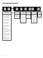
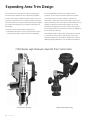
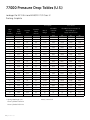
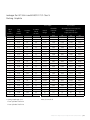
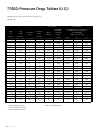
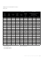
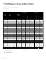
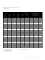
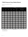
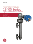
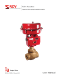
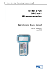
GE Oil & Gas
Technical Specifications
04/2013
Masoneilan* 77000 Series
High-Pressure Labyrinth
Trim Control Valve
These valves provide high pressure,
compressible fluid control
without the erosion,
vibration and high noise associated
with conventional control valves.
Table of Contents
Features and Benefits............................................................................. 2-3
General Data.................................................................................................... 3
Flow Coefficient (Cv) and Expansion Ratio......................................... 7
Bottom Entry 77000 Series Material Options.................................. 9
Numbering System........................................................................................ 4
Top Entry 77000 Series Material Options...................................... 11
Temperature Range/Seat Leakage........................................................ 5
Pressure Drop Tables (U.S.).......................................................... 12-15
Expanding Area Trim Design..................................................................... 6
Pressure Drop Tables (Metric)..................................................... 16-19
Sizes and Ratings (ANSI Class).................................................................. 7
Features and Benefits
GE’s Masoneilan* 77000 series high-pressure labyrinth trim control
valve from GE delivers exceptionally stable control and durable
service life while saving replacement and maintenance costs. It
provides high-pressure, compressible fluid control without the
erosion, vibration, and high noise associated with conventional
control valves.
Ideal for service in multi-phase flow applications, the Masoneilan*
77000 series valve’s advanced energy management trim design
stands up to the damaging and abrasive conditions caused by
entrained liquids/solids or liquids with entrained solids. It features
an expanding area flow passage, and its multiple step plug and
seat ring design creates a beneficial shearing action across each
stage to manage the gradual pressure reduction.
Energy Management Trim
This valve applies the principle of energy management
technology to gradually reduce pressure through the creation of
flow path friction. This simulates the gradual pressure loss that
occurs over long pipelines. By passing the fluid through a number
of restrictions, referred to as pressure reduction stages, the
Masoneilan* 77000 series valve’s tortuous flow pattern dissipates
energy through high head loss rather than through shock waves.
Additionally, the flow area of the trim is gradually increased at
the latter stages of the design to compensate for the volumetric
expansion of the gas caused by the reduction in pressure. This
ensures nearly constant fluid velocity throughout the complete
throttling process and eliminates the damaging effects of high
energy spikes within the trim.
The reduced velocity minimizes the impact of erosion caused
by entrained solids or liquids resulting from a process fluid
phase change. Plus, the acoustical performance of the valve
is optimized through alignment of the pressure drop ratio with
the trim expansion factor. In some cases, downstream Lo-dB
cartridges or custom design trim areas are integrated into the
control valve design for extremely high-pressure drop ratios.
The unique axial flow construction of the Masoneilan* 77000
series valve is optimal for flashing or de-gassing applications.
The axial flow path within the angle body design directs the twophase fluid away from critical surfaces and the downstream pipe
wall.
2 | GE Oil & Gas
Smooth, Stable Control
The high range (50:1) of this multi-stage valve allows wide
variations in controlled flow. Intermediate pressure flows through
internal plug porting for exceptional control stability. This creates a
balance force within the plug to minimize unbalanced force acting
on the trim.
What’s more, this uniquely balanced trim design has no secondary
balancing seal and only a single point for seat contact.
A toggle design for the actuation system provides high force
amplification through mechanical leverage resulting in stable
control during the throttling phase.
Adding GE’s Masoneilan* SVI* II Advanced Performance positioner
provides further process control, delivering high-precision valve
control and immediate response to the smallest step change in
signal.
Cavitation Elimination
The valve’s multi-stage trim design reduces the pressure drop in
smaller increments without allowing the local pressure at each
stage to drop below the fluid vapor pressure, thus preventing
cavitation. The actively controlled stages of this axial flow
design valve throttle in unison to avoid the adverse effects of an
exaggerated reduction at any single stage.
Dirt Tolerance
Wide flow paths in the trim allow for passage of large particles
entrained within the flow stream that would otherwise cause
damage or loss of capacity. This ensures continuous and efficient
operation by eliminating concerns of potential clogging due to
debris in the flow stream. GE’s Masoneilan* 77000 series valve
offers a proven design for many high-pressure, dirty service
applications, including wellhead choke valves.
Reliable Tight Shutoff
The standard seat design’s leakage rating meets IEC534-4 and
ANSI/FCI 70.2 Class V shutoff requirements. The valve can also be
supplied with block valve tight shutoff to comply with MSS-SP-61
specifications.
Features and Benefits
Ease of Maintenance
GE’s Masoneilan* 77000 series valve comes in two design styles
for easy trim access in the field; a bottom-loaded flanged end
connection design and a top-loaded butt-weld end design provide
field maintenance flexibility.
In addition, short valve travel reduces packing wear and
significantly extends packing life, particularly in high-pressure/
high-temperature service.
Enhanced service life is achieved through the trim’s heavy guiding
coupled with the use of hardened materials on the seat and
guiding surfaces.
in NACE standard MR0103. Product configurations for applications
requiring MR0175 – 2003 or ISO 15156 compliance are also
available. In addition, the valve is designed for compliance with
Pressure Equipment Directives (PED) requirements.
Noise Prediction
Valve noise calculations can be performed using GE’s Masoneilan*
sizing and selection program based on the latest IEC equations.
Since noise intensity of a free gas jet varies to the eighth power of
the velocity, a 4:1 reduction in fluid through the expanding area can
reduce the expected noise level approximately 255 times (equivalent
to 24 dB). When predicting the overall noise level produced by the
control valve system, calculations of the noise levels at all stages of
the trim and at the outlet area are all considered.
NACE and PED Compliance
GE’s Masoneilan 77000 series valve is available for sour service
applications using the design and construction methods defined
General Data
• Trim
Flow Direction
Standard: Flow-to-open
• Body
Type: Cast or forged angle style
Sizes: 1-inch to 8-inch (expanding outlets available) (DN 25
to 200)
Ratings:ANSI Class 600 to 2500 (ISO PN 100 to 420)
API Class 2000 to 10000
End Connections:RF Flange, RTJ flange
Print flanges (forgings only)
BWE and SWE (available for 2-inch and under)
• Bonnet
Type:Bottom entry; bolted outlet spool Top entry; bolted bonnet
• Body and Bonnet
Materials:Carbon steel
Stainless steel
Chrome-moly
Plug type:Multi-stage axial flow
(Trim A, B, C options)
Seat type:
Metal seat
Guide:
Top and bottom guiding
Cv Ratio:
See table (page 7)
Flow Characteristic:
Linear
• Actuator
Mounting:
Toggle arm mount
Direct mount
Type:
Spring-diaphragm
Spring-return cylinder
Double-acting cylinder
Handwheel:
Optional
Optional designs are also available, such as larger sizes,
higher pressure ratings, special materials, modified staging,
and other configurations as required. Contact GE for design
details and specifications.
77000 Series High Pressure Labyrinth Trim Control Valves | 3
Numbering System
1st
2nd
Actuator Type
Spring Diaphragm
37Spring-diaphragm
direct, air to open
(fail close action)
38Spring-diaphragm
reverse, air to close
(fail open action)
87Spring-diaphragm
direct, air to open
(fail close action)
88Spring-diaphragm
reverse, air to close
(fail open action)
Piston Cylinder
84
Cylinder: spring return,
direct, air to open,
single or double acting
(fail close action)
85
Cylinder: spring return,
reverse air to close,
single or double acting
(fail open action)
86Cylinder:
double acting, without
spring, air to open or
air to close action
4 | GE Oil & Gas
1st
2nd
7
7
Body Series
77Multi-stage,
axial flow
labyrinth trim control valve
3rd
Trim Type
0Undefined
1 Trim A
unbalanced
2 Trim B
unbalanced
3 Trim C
unbalanced
4th
Trim
Charateristic
0Undefined
1Linear
5th
Design
0Undefined
1 Bottom entry; outlet spool design
2 Top entry;
bolted
bonnet
design
6th
Options
FForged
Body
Temperature Range/Seat Leakage
Valve
Size (3)
ANSI
Class
API
Rating
Trim
Type
Seat
Type
1-inch x
2-inch
through
600
through
2500
2000
through
10000
Unbalanced
Metal
Temperature Range (1)
Min.
Max.
-20° F
(-29° C)
1050° F
(565° C)
Seat
Leakage (2)
IV
or
V
1. Designs for higher or lower temperatures are available. Please consult GE.
2. Seat leakage class ratings per IEC 534-4 and ANSI/FCI 70.2. Class IV is the standard and Class V is optional.
3. Inlet and outlet connections also available with API size ranges.
77000 Series High Pressure Labyrinth Trim Control Valves | 5
Expanding Area Trim Design
The circumference of each pressure reduction stage within
the Masoneilan* 77000 series trim is designed to gradually
increase as flow moves towards the downstream section. This
expansion compensates for the change in gas density with the
pressure and ensures a nearly constant fluid velocity throughout
the complete throttling process, providing the valve with two
advantages:
1. Reduction in noise produced by the fluid velocity
2.Considerable decrease in erosion of the plug and seat liner
caused by particulate in the flow stream or fluid flashing
For many applications that experience flashing service
conditions, such as supercritical power plant start-up valves
or hot high-pressure separator letdown in refineries, the
Masoneilan* 77000 series valve provides a low-velocity outlet
area to minimize any effect of the phase transformation process.
Similarly for applications with entrained solids, such as gas
wellhead choke applications, the valve reduces the velocity of
the moving particulate to minimize wear and erosive damage to
the trim and outlet flow area.
Many designs include a larger outlet compared to the inlet size
to retain the low velocity as the fluid exits the valve into the
downstream piping. This arrangement eliminates the need for
additional piping modifications, such as downstream reducers.
77000 Series High-Pressure Labyrinth Trim Control Valve
77000 Series Top Entry
6 | GE Oil & Gas
77000 Series Bottom Entry
Sizes and Ratings (ANSI Class)
¨RF Flange £Socket Weld ¡Threaded uRTJ Flange nButt Weld
Valve
Size (inch)
1
2
3
4
6
8
Outlet
Options
ANSI 600(1)
API 2000
ANSI 900(1)
API 3000
ANSI 1500(1)
API 5000
ANSI 2500
API 10000
1
¨£¡un
¨£¡un
¨£¡un
¨£¡un
2
¨£¡un
¨£¡un
¨£¡un
¨£¡un
3
¨£¡un
¨£¡un
¨£¡un
¨£¡un
2
¨£¡un
¨£¡un
¨£¡un
¨£¡un
3
¨£¡un
¨£¡un
¨£¡un
¨£¡un
4
¨£¡un
¨£¡un
¨£¡un
¨£¡un
3
¨un
¨un
¨un
¨un
4
¨un
¨un
¨un
¨un
6
¨un
¨un
¨un
¨un
4
¨un
¨un
¨un
¨un
6
¨un
¨un
¨un
¨un
8
¨un
¨un
¨un
¨un
6
¨un
¨un
¨un
¨un
8
¨un
¨un
¨un
¨un
10
¨un
¨un
¨un
¨un
8
¨un
¨un
¨un
¨un
10
¨un
¨un
¨un
¨un
12
¨un
¨un
¨un
¨un
1) Machined from an ANSI 1500/API 5000 rated body 2) API and special valve connections available upon request
Flow Coefficient (Cv) and Expansion Ratio
Trim Size
Valve Size
(inch)
1
2
3
4
6
8
Outlet Options
(Inch)
A
B
C
Expansion
Ratio
Cv
Expansion
Ratio
Cv
Expansion
Ratio
Cv
1
4:1
2
2:1
4
1.5:1
6
2
4:1
2
2:1
4
1.5:1
6
3
4:1
2
2:1
4
1.5:1
6
2
4:1
12
2:1
22
1.5:1
35
3
4:1
12
2:1
22
1.5:1
35
4
4:1
12
2:1
22
1.5:1
35
3
4:1
31
2:1
45
1.5:1
72
4
4:1
31
2:1
45
1.5:1
72
6
4:1
31
2:1
45
1.5:1
72
4
4:1
54
2:1
72
1.5:1
110
6
4:1
54
2:1
72
1.5:1
110
8
4:1
54
2:1
72
1.5:1
110
6
4:1
72
2:1
120
1.5:1
170
8
4:1
72
2:1
120
1.5:1
170
10
4:1
72
2:1
120
1.5:1
170
8
4:1
120
2:1
180
1.5:1
260
10
4:1
120
2:1
180
1.5:1
260
12
4:1
120
2:1
180
1.5:1
260
* Note: Special designs with oversized and reduced Cv trim are available. Please consult GE.
77000 Series High Pressure Labyrinth Trim Control Valves | 7
8 | GE Oil & Gas
Bottom Entry 77000 Series Material Options
Ref
No.
650°F
(340°C)
Temperature Range
Description
800ºF
(427°C)
950°F
(510°C)
1050°F
(565°C)
Standard Materials and Optional Materials
ASTM A216 WCC Carbon Steel/ASTM A105 Carbon Steel
ASTM A217 WC6 Chrome-Moly/ASTM A182 F11 Chrome-Moly
1
Body
ASTM A217 WC9 Chrome-Moly/ASTM A182 F22 Chrome-Moly
ASTM A351 CF8M Stainless Steel/ASTM A182 F316 Stainless Steel
ASTM A351 CF8C Stainless Steel/ASTM A182 F347 Stainless Steel
ASTM A216 WCC Carbon Steel/ASTM A105 Carbon Steel
ASTM A217 WC6 Chrome-Moly/ASTM A182 F11 Chrome-Moly
2
Outlet Spool
ASTM A217 WC9 Chrome-Moly/ASTM A182 F22 Chrome-Moly
ASTM A351 CF8M Stainless Steel/ASTM A182 F316 Stainless Steel
ASTM A351 CF8C Stainless Steel/ASTM A182 F347 Stainless Steel
3
Seat Ring
316 St. St. or 347 St. St. Boronized with Hardfaced Seat
4
Spider
316 St. St. or 347 St. St.
5
Plug Stem
316 St. St. or 347 St. St. Boronized with Hardfaced Seat
Stellite® 6 UNS 30006
6
Stem Guide Bushing
7
Lower Spider Gasket
316 St. St. with Flexible Graphite Filler (Spiral Wound)
Inconel® with Graphite (Spiral Wound)
8
Upper Spider Gasket
316 St. St. with Flexible Graphite Filler (Spiral Wound)
Inconel® with Graphite (Spiral Wound)
9
Body Stud (1)
ASTM A193 Gr B7 (2) or ASTM A193 Gr B7M (3)
ASTM A193
Gr B16
ASTM A453
Gr 660
10
Bonnet/Spool Nut (1)
ASTM A194 Gr 2H (2) or ASTM A19F Gr2HM (3)
ASTM A194
Gr 4
ASTM A194
Gr 8
11
Packing Set
Teflon® V-Ring
12
Lantern Ring
300 Series Stainless Steel
13
Packing Follower
300 Series Stainless Steel
14
Packing Flange
Flexible Graphite
300 Series Stainless Steel or Chrome Moly
(1)
304 Stainless Steel ASTM A193 Gr B8 Class 2 (2) or ASTM A193 Gr B7M Nickel Plated 3)
15
Packing Flange Stud
16
Packing Flange Nut (1)
304 Stainless Steel ASTM A194 Gr 8 (2) or ASTM A194 Gr 2HM Nickel Plated (3)
17
Actuator Toggle Bracket
ASTM A36 Carbon Steel
18
Bracket Stud (1)
ASTM A193 Gr B7
19
Bracket Nut (1)
ASTM A194 Gr 2H
20
Body Clevis
ASTM A36 Carbon Steel
21
Body Clevis Pin
440 C Stainless Steel
22
Body Clevis Retaining Ring
ASTM A564 Gr 632
23
Lever
ASTM A36 Carbon Steel
24
Stem Pivot Adapter
300 Series Stainless Steel
25
Anti-Rotation Screw
300 Series Stainless Steel
26
Locknut
ASTM A194 Gr 8
27
Actuator Link Connector
300 Series Stainless Steel
28
Actuator Link Pin
440 C Stainless Steel
29
Actuator Link Retaining Ring
ASTM A564 Gr 632
30
Travel Stop Stud
300 Series Stainless Steel
31
Travel Stop Nut
300 Series Stainless Steel
32
Drive Nut
Carbon Steel ASTM A668 CL B or ASTM A2165 Gr WCC
36
Spud Adapter
300 Series Stainless Steel
37
Actuator Link Clevis
(Sizes from 1 to 3 inches)
ASTM A36 Carbon Steel
Notes:
(1) Studs and Nuts are Nickel or Zinc Plated for use with Stainless Steel Bodies.
(2) Non-Nace and Nace Non-Exposed (Class III)
(3) Nace Exposed (Class I & II)
77000 Series High Pressure Labyrinth Trim Control Valves | 9
10 | GE Oil & Gas
Top Entry 77000 Series Material Options
Ref
No.
650°F
(340°C)
Temperature Range
Description
800°F
(427°C)
950°F
(510°C)
1050°F
(565°C)
Standard Materials and Optional Materials
ASTM A216 WCC Carbon Steel/ASTM A105 Carbon Steel
ASTM A217 WC6 Chrome-Moly/ASTM A182 F11 Chrome-Moly
1
Body
ASTM A217 WC9 Chrome-Moly/ASTM A182 F22 Chrome-Moly
ASTM A351 CF8M Stainless Steel/ASTM A182 F316 Stainless Steel
ASTM A351 CF8C Stainless Steel/ASTM A182 F347 Stainless Steel
ASTM A216 WCC Carbon Steel/ASTM A105 Carbon Steel
ASTM A217 WC6 Chrome-Moly/ STM A182 F11 Chrome-Moly
2
Bonnet
ASTM A217 WC9 Chrome-Moly/ASTM A182 F22 Chrome-Moly
ASTM A351 CF8M Stainless Steel/ASTM A182 F316 Stainless Steel
ASTM A351 CF8C Stainless Steel/ASTM A182 F347 Stainless Steel
3
Seat Ring
316 St. St. or 347 St. St. Boronized with Hardfaced Seat
4
Spider
316 St. St. or 347 St. St.
5
Plug Stem
316 St. St. or 347 St. St. Boronized with Hardfaced Seat
6
Stem Guide Bushing
Stellite® 6 UNS 30006
7
Lower Spider Gasket
316 St. St. with Flexible Graphite Filler (Spiral Wound)
Inconel® w/ Graphite (Spiral Wound)
8
Upper Spider Gasket
316 St. St. with Flexible Graphite Filler (Spiral Wound)
Inconel® w/ Graphite (Spiral Wound)
9
Body Stud (1)
ASTM A193 Gr B7 (2) or ASTM A193 Gr B7M (3)
ASTM A193
Gr B16
ASTM A453
Gr 660
10
Bonnet / Spool Nut (1)
ASTM A194 Gr 2H (2) or ASTM A193 Gr 2HM (3)
ASTM A194
Gr 4
ASTM A194
Gr 8
11
Packing Set
Teflon® V-Ring
12
Lantern Ring
300 Series Stainless Steel
13
Packing Follower
300 Series Stainless Steel
14
Packing Flange
300 Series Stainless Steel or Chrome Moly
15
Packing Flange Stud (1)
304 Stainless Steel ASTM A193 Gr B8 Class 2 (2) or ASTM A193 Gr B7M Nickel Plated (3)
16
Packing Flange Nut (1)
304 Stainless Steel ASTM A194 Gr 8 (2) or ASTM A194 Gr 2HM Nickel Plated (3)
17
Actuator Toggle Bracket
ASTM A36 Carbon Steel
18
Bracket Stud (1)
ASTM A193 Gr B7
19
Bracket Nut (1)
ASTM A194 Gr 2H
20
Body Clevis
ASTM A36 Carbon Steel
21
Body Clevis Pin
440 C Stainless Steel
ASTM A564 Gr 632
22
Body Clevis Retaining Ring
23
Lever
ASTM A36 Carbon Steel
24
Stem Pivot Adapter
300 Series Stainless Steel
25
Anti-Rotation Screw
300 Series Stainless Steel
26
Locknut
ASTM A194 Gr 8
27
Actuator Link Connector
300 Series Stainless Steel
28
Actuator Link Pin
440 C Stainless Steel
29
Actuator Link Retaining Ring
ASTM A564 Gr 632
30
Travel Stop Stud
300 Series Stainless Steel
300 Series Stainless Steel
Flexible Graphite
31
Travel Stop Nut
32
Drive Nut
Carbon Steel ASTM A668 CL B or ASTM A2165 Gr WCC
33
Seat Ring Retainer
316 St. St. or 347 St. St.
34
Bonnet Gasket
316 St. St. with Flexible Graphite Filler (Spiral Wound)
Inconel® with Graphite (Spiral Wound)
35
Lower Guide Bushing
RTFE
Stellite® 6 UNS 30006
37
Actuator Link Clevis
(Sizes from 1 to 3 inches)
ASTM A36 Carbon Steel
38
Conical Spring
Inconel 718
Notes:
(1) Studs and Nuts are Nickel or Zinc Plated for use with Stainless Steel Bodies.
(2) Non-Nace and Nace Non-Exposed (Class III)
(3) Nace Exposed (Class I & II)
77000 Series High Pressure Labyrinth Trim Control Valves | 11
77000 Pressure Drop Tables (U.S.)
Leakage: Per IEC 534-4 and ANSI/FCI 70.2 Class IV
Packing: Graphite
Air to Open
Actuator
Valve
Plug
Size
Travel
(Inches)
(Inches)
1
0.25
6
0.8
1
0.25
10
1
0.25
2
Actuator
Size
Travel
(Inches)
Air to Close
Allowable
Allowable Pressure Drop (PSI)
Bench
Pressure
Bench Range **
Range
Drop
Supply Pressure (PSI)
(PSI)
30
35
40
21-45
4855
3435
4609
5797
0.8
21-45
7200
5797
7200
7200
16
0.8
21-45
7200
7200
7200
7200
0.25
10
1.5
21-45
3058
2159
2899
3652
2
0.25
16
1.5
11-23
2551
3493
4681
5870
2
0.25
23
1.5
11-23
3696
5058
6768
7200
2
0.25
15
1.5
12-30
3101
3884
5203
6522
2
0.25
15
1.5
14-31
3565
3884
5203
6522
3
0.38
10
2.5
21-45
1725
1435
1638
2058
3
0.38
16
2.5
21-45
2783
1971
2652
3319
3
0.38
23
2.5
11-23
2087
2855
3826
4797
3
0.38
18
2.5
12-30
2522
3159
4232
5304
3
0.38
18
2.5
15-33
3159
3159
4232
5304
4
0.50
24
3.5
9-30
2290
3841
5145
6435
4
0.50
24
3.5
18-45
4623
3841
5145
6435
4
0.50
154
3.5
35-50
3246
1435
1884
2348
4
0.50
314
3.5
35-50
6652
2290
3232
4174
6
0.50
24
3.5
19-46
3594
2638
3536
4420
6
0.50
24
3.5
21-49
4275
2638
3536
4420
6
0.50
154
3.5
35-50
2232
1435
1435
1609
6
0.50
314
3.5
35-50
4580
1565
2217
2870
8
1.00
24
3.5
(1)
(1)
(1)
(1)
(1)
8
1.00
24
3.5
(1)
(1)
(1)
(1)
(1)
8
1.00
154
3.5
(1)
(1)
(1)
(1)
(1)
8
1.00
314
3.5
(1)
(1)
(1)
(1)
(1)
** Spring Diaphragm 3-15
Piston Cylinder 154/10-14
Piston Cylinder 314/12-18
12 | GE Oil & Gas
Note (1) Consult GE
Leakage: Per IEC 534-4 and ANSI/FCI 70.2 Class V
Packing: Graphite
Air to Open
Actuator
Valve
Plug
Size
Travel
(Inches)
(Inches)
1
0.25
6
0.8
1
0.25
10
1
0.25
2
Actuator
Size
Travel
(Inches)
Air to Close
Allowable
Allowable Pressure Drop (PSI)
Bench
Pressure
Bench Range **
Range
Drop
Supply Pressure (PSI)
(PSI)
30
35
40
21-45
4507
3101
4275
5449
0.8
21-45
7200
5449
7200
7200
16
0.8
21-45
7200
7200
7200
7200
0.25
10
1.5
21-45
2841
1957
2696
3435
2
0.25
16
1.5
11-23
2333
3290
4478
5667
2
0.25
23
1.5
11-23
3478
4841
6551
7200
2
0.25
15
1.5
12-30
2884
3681
5000
6304
2
0.25
15
1.5
14-31
3348
3681
5000
6304
3
0.38
10
2.5
21-45
1551
1435
1464
1899
3
0.38
16
2.5
21-45
2623
1812
2478
3159
3
0.38
23
2.5
11-23
1913
2696
3667
4638
3
0.38
18
2.5
12-30
2348
3000
4072
5145
3
0.38
18
2.5
15-33
3000
3000
4072
5145
4
0.50
24
3.5
9-30
2159
3710
5000
6304
4
0.50
24
3.5
18-45
4478
3710
5000
6304
4
0.50
154
3.5
35-50
3101
1435
1754
2217
4
0.50
314
3.5
35-50
6522
2145
3087
4043
6
0.50
24
3.5
19-46
3478
2522
3420
4304
6
0.50
24
3.5
21-49
4159
2522
3420
4304
6
0.50
154
3.5
35-50
2116
1435
1435
1493
6
0.50
314
3.5
35-50
4464
1449
2101
2754
8
1.00
24
3.5
(1)
(1)
(1)
(1)
(1)
8
1.00
24
3.5
(1)
(1)
(1)
(1)
(1)
8
1.00
154
3.5
(1)
(1)
(1)
(1)
(1)
8
1.00
314
3.5
(1)
(1)
(1)
(1)
(1)
** Spring Diaphragm 3-15
Note (1) Consult GE
Piston Cylinder 154/10-14
Piston Cylinder 314/12-18
77000 Series High Pressure Labyrinth Trim Control Valves | 13
77000 Pressure Drop Tables (U.S.)
Leakage: Per IEC 534-4 and ANSI/FCI 70.2 Class IV
Packing: PTFE
Air to Open
Actuator
Valve
Plug
Size
Travel
(Inches)
(Inches)
1
0.25
6
0.8
1
0.25
10
Actuator
Size
Travel
(Inches)
Air to Close
Allowable
Allowable Pressure Drop (PSI)
Bench
Pressure
Bench Range **
Range
Drop
Supply Pressure (PSI)
(PSI)
30
35
40
21-45
7200
5435
7200
7200
0.8
21-45
7200
7200
7200
7200
2
0.25
10
1.5
21-45
4797
3406
4565
5725
2
0.25
16
1.5
11-23
4014
5493
7200
7200
2
0.25
23
1.5
11-23
5797
7200
7200
7200
2
0.25
15
1.5
12-30
4870
6116
7200
7200
2
0.25
15
1.5
14-31
5594
6116
7200
7200
3
0.38
10
2.5
21-45
2493
1768
2377
2986
3
0.38
16
2.5
21-45
4029
2855
3826
4812
3
0.38
23
2.5
11-23
3014
4145
5536
6942
3
0.38
18
2.5
12-30
3652
4580
6130
7200
3
0.38
18
2.5
15-33
4580
4580
6130
7200
4
0.50
24
3.5
9-30
3449
5797
7200
7200
4
0.50
24
3.5
18-45
6957
5797
7200
7200
4
0.50
154
3.5
35-50
4884
2159
2855
3551
4
0.50
314
3.5
35-50
7200
3449
4870
6290
6
0.50
24
3.5
19-46
4754
3493
4667
5841
6
0.50
24
3.5
21-49
5638
3493
4667
5841
6
0.50
154
3.5
35-50
2942
1435
1710
2130
6
0.50
314
3.5
35-50
6043
2072
2928
3783
8
1.00
24
3.5
(1)
(1)
(1)
(1)
(1)
8
1.00
24
3.5
(1)
(1)
(1)
(1)
(1)
8
1.00
154
3.5
(1)
(1)
(1)
(1)
(1)
8
1.00
314
3.5
(1)
(1)
(1)
(1)
(1)
** Spring Diaphragm 3-15
Piston Cylinder 154/10-14
Piston Cylinder 314/12-18
14 | GE Oil & Gas
Note (1) Consult Factory
Leakage: Per IEC 534-4 and ANSI/FCI 70.2 Class V
Packing: PTFE
Air to Open
Actuator
Valve
Plug
Size
Travel
(Inches)
(Inches)
1
0.25
6
0.8
1
0.25
10
2
0.25
2
Actuator
Size
Travel
(Inches)
Air to Close
Allowable
Allowable Pressure Drop (PSI)
Bench
Pressure
Bench Range **
Range
Drop
Supply Pressure (PSI)
(PSI)
30
35
40
21-45
7130
4899
6768
7200
0.8
21-45
7200
7200
7200
7200
10
1.5
21-45
4464
3072
4232
5406
0.25
16
1.5
11-23
3681
5174
7029
7200
2
0.25
23
1.5
11-23
5478
7200
7200
7200
2
0.25
15
1.5
12-30
4536
5783
7200
7200
2
0.25
15
1.5
14-31
5261
5783
7200
7200
3
0.38
10
2.5
21-45
2246
1522
2130
2739
3
0.38
16
2.5
21-45
3783
2623
3594
4565
3
0.38
23
2.5
11-23
2783
3899
5304
6696
3
0.38
18
2.5
12-30
3406
4333
5884
7200
3
0.38
18
2.5
15-33
4333
4333
5884
7200
4
0.50
24
3.5
9-30
3246
5594
7200
7200
4
0.50
24
3.5
18-45
6754
5594
7200
7200
4
0.50
154
3.5
35-50
4681
1942
2652
3348
4
0.50
314
3.5
35-50
7200
3232
4667
6087
6
0.50
24
3.5
19-46
4594
3333
4507
5696
6
0.50
24
3.5
21-49
5478
3333
4507
5696
6
0.50
154
3.5
35-50
2783
1435
1565
1986
6
0.50
314
3.5
35-50
5899
1913
2783
3638
8
1.00
24
3.5
(1)
(1)
(1)
(1)
(1)
8
1.00
24
3.5
(1)
(1)
(1)
(1)
(1)
8
1.00
154
3.5
(1)
(1)
(1)
(1)
(1)
8
1.00
314
3.5
(1)
(1)
(1)
(1)
(1)
** Spring Diaphragm 3-15
Note (1) Consult Factory
Piston Cylinder 154/10-14
Piston Cylinder 314/12-18
77000 Series High Pressure Labyrinth Trim Control Valves | 15
77000 Pressure Drop Tables (Metric)
Leakage: Per IEC 534-4 and ANSI/FCI 70.2 Class IV
Packing: Graphite
Air to Open
Actuator
Valve
Plug
Size
Travel
(Inches)
(mm)
1
6
6
20
1
6
10
20
1
6
16
20
2
6
10
38
2
6
16
38
2
6
23
2
6
2
Actuator
Size
Travel
(mm)
Air to Close
Allowable
Allowable Pressure Drop (Bar)
Bench
Pressure
Bench Range **
Range
Drop
Supply Pressure (Bar)
(Bar)
2.1
2.4
2.8
21-45
335
237
318
400
21-45
497
400
497
497
21-45
497
497
497
497
21-45
211
149
200
252
11-23
176
241
323
405
38
11-23
255
349
467
497
15
38
12-30
214
268
359
450
6
15
38
14-31
246
268
359
450
3
9
10
63
21-45
119
99
113
142
3
9
16
63
21-45
192
136
183
229
3
9
23
63
11-23
144
197
264
331
3
9
18
63
12-30
174
218
292
366
3
9
18
63
15-33
218
218
292
366
4
13
24
88
9-30
158
265
355
444
4
13
24
88
18-45
319
265
355
444
4
13
154
88
35-50
224
99
130
162
4
13
314
88
35-50
459
158
223
288
6
13
24
88
19-46
248
182
244
305
6
13
24
88
21-49
295
182
244
305
6
13
154
88
35-50
154
99
99
111
6
13
314
88
35-50
316
108
153
198
8
25
24
88
(1)
(1)
(1)
(1)
(1)
8
25
24
88
(1)
(1)
(1)
(1)
(1)
8
25
154
88
(1)
(1)
(1)
(1)
(1)
8
25
314
88
(1)
(1)
(1)
(1)
(1)
** Spring Diaphragm 3-15
Piston Cylinder 154/10-14
Piston Cylinder 314/12-18
16 | GE Oil & Gas
Note (1) Consult Factory
Leakage: Per IEC 534-4 and ANSI/FCI 70.2 Class V
Packing: Graphite
Air to Open
Actuator
Valve
Plug
Size
Travel
(Inches)
(mm)
1
0.25
6
20
1
0.25
10
1
0.25
2
Actuator
Size
Travel
(mm)
Air to Close
Allowable
Allowable Pressure Drop (Bar)
Bench
Pressure
Bench Range **
Range
Drop
Supply Pressure (Bar)
(Bar)
2.1
2.4
2.8
21-45
311
214
295
376
20
21-45
497
376
497
497
16
20
21-45
497
497
497
497
6
10
38
21-45
196
135
186
237
2
6
16
38
11-23
161
227
309
391
2
6
23
38
11-23
240
334
452
497
2
6
15
38
12-30
199
254
345
435
2
6
15
38
14-31
231
254
345
435
3
9
10
63
21-45
107
99
101
131
3
9
16
63
21-45
181
125
171
218
3
9
23
63
11-23
132
186
253
320
3
9
18
63
12-30
162
207
281
355
3
9
18
63
15-33
207
207
281
355
4
13
24
88
9-30
149
256
345
435
4
13
24
88
18-45
309
256
345
435
4
13
154
88
35-50
214
99
121
153
4
13
314
88
35-50
450
148
213
279
6
13
24
88
19-46
240
174
236
297
6
13
24
88
21-49
287
174
236
297
6
13
154
88
35-50
146
99
99
103
6
13
314
88
35-50
308
100
145
190
8
25
24
88
(1)
(1)
(1)
(1)
(1)
8
25
24
88
(1)
(1)
(1)
(1)
(1)
8
25
154
88
(1)
(1)
(1)
(1)
(1)
8
25
314
88
(1)
(1)
(1)
(1)
(1)
** Spring Diaphragm 3-15
Note (1) Consult Factory
Piston Cylinder 154/10-14
Piston Cylinder 314/12-18
77000 Series High Pressure Labyrinth Trim Control Valves | 17
77000 Pressure Drop Tables (Metric)
Leakage: Per IEC 534-4 and ANSI/FCI 70.2 Class IV
Packing: PTFE
Air to Open
Actuator
Valve
Plug
Size
Travel
(Inches)
(mm)
1
6
6
20
1
6
10
2
6
2
Actuator
Size
Travel
(mm)
Air to Close
Allowable
Allowable Pressure Drop (Bar)
Bench
Pressure
Bench Range **
Range
Drop
Supply Pressure (Bar)
(Bar)
2.1
2.4
2.8
21-45
497
375
497
497
20
21-45
497
497
497
497
10
38
21-45
331
235
315
395
6
16
38
11-23
277
379
497
497
2
6
23
38
11-23
400
497
497
497
2
6
15
38
12-30
336
422
497
497
2
6
15
38
14-31
386
422
497
497
3
9
10
63
21-45
172
122
164
206
3
9
16
63
21-45
278
197
264
332
3
9
23
63
11-23
208
286
382
479
3
9
18
63
12-30
252
316
423
497
3
9
18
63
15-33
316
316
423
497
4
13
24
88
9-30
238
400
497
497
4
13
24
88
18-45
480
400
497
497
4
13
154
88
35-50
337
149
197
245
4
13
314
88
35-50
497
238
336
434
6
13
24
88
19-46
328
241
322
403
6
13
24
88
21-49
389
241
322
403
6
13
154
88
35-50
203
99
118
147
6
13
314
88
35-50
417
143
202
261
8
25
24
88
(1)
(1)
(1)
(1)
(1)
8
25
24
88
(1)
(1)
(1)
(1)
(1)
8
25
154
88
(1)
(1)
(1)
(1)
(1)
8
25
314
88
(1)
(1)
(1)
(1)
(1)
** Spring Diaphragm 3-15
Piston Cylinder 154/10-14
Piston Cylinder 314/12-18
18 | GE Oil & Gas
Note (1) Consult GE
Leakage: Per IEC 534-4 and ANSI/FCI 70.2 Class V
Packing: PTFE
Air to Open
Actuator
Valve
Plug
Size
Travel
(Inches)
(mm)
1
6
6
20
1
6
10
2
6
2
Actuator
Size
Travel
(mm)
Air to Close
Allowable
Allowable Pressure Drop (Bar)
Bench
Pressure
Bench Range **
Range
Drop
Supply Pressure (Bar)
(Bar)
2.1
2.4
2.8
21-45
497
338
467
497
20
21-45
497
497
467
497
10
38
21-45
308
212
292
373
6
16
38
11-23
254
357
485
497
2
6
23
38
11-23
378
497
497
497
2
6
15
38
12-30
313
399
497
497
2
6
15
38
14-31
363
399
497
497
3
9
10
63
21-45
155
105
147
189
3
9
16
63
21-45
261
181
248
315
3
9
23
63
11-23
192
269
366
462
3
9
18
63
12-30
235
299
406
497
3
9
18
63
15-33
299
299
406
497
4
13
24
88
9-30
224
386
497
497
4
13
24
88
18-45
466
386
497
497
4
13
154
88
35-50
323
134
183
231
4
13
314
88
35-50
497
223
322
420
6
13
24
88
19-46
317
230
311
393
6
13
24
88
21-49
378
230
311
393
6
13
154
88
35-50
192
99
108
137
6
13
314
88
35-50
407
132
192
251
8
25
24
88
(1)
(1)
(1)
(1)
(1)
8
25
24
88
(1)
(1)
(1)
(1)
(1)
8
25
154
88
(1)
(1)
(1)
(1)
(1)
8
25
314
88
(1)
(1)
(1)
(1)
(1)
** Spring Diaphragm 3-15
Note (1) Consult GE
Piston Cylinder 154/10-14
Piston Cylinder 314/12-18
77000 Series High Pressure Labyrinth Trim Control Valves | 19
DIRECT SALES OFFICE LOCATIONS
BELGIUM
Phone:+32-2-344-0970
Fax:+32-2-344-1123
KOREA
Phone:+82-2-2274-0748
Fax:+82-2-2274-0794
BRAZIL
Phone:+55-11-2146-3600
Fax:+55-11-2146-3610
MALAYSIA
Phone:+60-3-2161-0322
Fax:+60-3-2163-6312
CHINA
Phone:+86-10-5689-3600
Fax:+86-10-5689-3800
MEXICO
Phone:+52-55-3640-5060
FRANCE
Courbevoie
Phone:+33-1-4904-9000
Fax:+33-1-4904-9010
GERMANY
Ratingen
Phone:+49-2102-108-0
Fax:+49-2102-108-111
INDIA
Mumbai
Phone:+91-22-8354790
Fax:+91-22-8354791
New Delhi
Phone:+91-11-2-6164175
Fax:+91-11-5-1659635
ITALY
Phone:+39-081-7892-111
Fax:+39-081-7892-208
THE NETHERLANDS
Phone:+0031-15-3808666
Fax:+0031-18-1641438
RUSSIA
Veliky Novgorod
Phone:+7-8162-55-7898
Fax:+7-8162-55-7921
Moscow
Phone:
Fax:
+7 495-585-1276
+7 495-585-1279
SAUDI ARABIA
Phone:+966-3-341-0278
Fax:+966-3-341-7624
SINGAPORE
Phone:+65-6861-6100
Fax:+65-6861-7172
SOUTH AFRICA
Phone:+27-11-452-1550
Fax:+27-11-452-6542
SOUTH and CENTRAL
AMERICA and the CARIBBEAN
Phone:+55-12-2134-1201
Fax:+55-12-2134-1238
SPAIN
Phone:+34-93-652-6430
Fax:+34-93-652-6444
UNITED ARAB EMIRATES
Phone:+971-4-8991-777
Fax:+971-4-8991-778
UNITED KINGDOM
Wooburn Green
Phone:+44-1628-536300
Fax:+44-1628-536319
UNITED STATES
Massachusetts
Phone:+1-508-586-4600
Fax:+1-508-427-8971
Corpus Christi, Texas
Phone:+1-361-881-8182
Fax:+1-361-881-8246
Deer Park, Texas
Phone:+1-281-884-1000
Fax:+1-281-884-1010
Houston, Texas
Phone:+1-281-671-1640
Fax:+1-281-671-1735
JAPAN Chiba
Phone:+81-43-297-9222
Fax:+81-43-299-1115
* Trademark of General Electric Company
Other company names and product names used in this document are the registered trademarks
or trademarks of their respective owners.
© 2014 General Electric Company. All rights reserved.
GEA20210A 07/2014