1
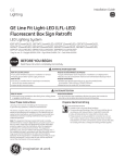
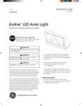
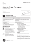
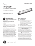
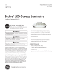
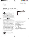
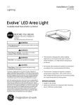
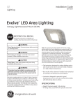
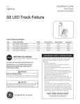
GE
Installation Guide
24
Lighting Solutions
Volt
GE Line Fit Light-LED (LFL-LED)
Fluorescent Box Sign Retrofit
LED Lighting System
(GEF12T12DHOLED, GEF12T12SGNHOLED, GEF12T12CWHOLED)*
* key: D = Daylight (6500K), SGN = Sign White (5400K), CW = Cool White (4100K)
BEFORE YOU BEGIN
Read these instructions completely and carefully.
WARNING/AVERTISSEMENT
RISK OF ELECTRIC SHOCK
• Turn power off before inspection, installation or removal.
• Properly ground Tetra® power supply enclosure.
RISK OF FIRE
• Use only UL certified wire for input/output connections.
Minimum size 18 AWG (0.82mm2).
• Follow all NEC and local codes.
RISQUES DE DÉCHARGES ÉLECTRIQUES
• Coupez l’alimentation avant l’inspection, l’installation ou le déplacement.
• Assurez-vous de correctement mettre à terre l’alimentation électrique Tetra®.
RISQUES D’INCENDIE
• N’utilisez que des fils approuvés par UL pour les entrées/sorties de connexion. Taille minimum 18 AWG (0.82mm2).
• Respectez tous les codes NEC et codes locaux.
CAUTION/ATTENTION
RISK OF INJURY
RISQUE DE BLESSURE
• While performing installations described, gloves, safety glasses • Lors de l’exécution des installations décrites, des gants, des lunettes de sécurité or goggles should be worn.
ou des lunettes de protection doivent être portées.
Save These Instructions
Use only in the manner intended by the manufacturer.
If you have any questions, contact the manufacturer.
Prepare Electrical Wiring
Electrical Requirements
• Limited to use in dry and damp locations.
• The grounding and bonding of the LED Driver shall be done in accordance with National Electric Code (NEC) Article 600.
• Follow all National Electric Codes (NEC) and local codes.
• These products are only suitable for connection to a circuit from a Class 2 power source. These products have not been evaluated for use when connected to a power source that does not comply with Class 2 voltage and energy limited supplies.
This device complies with part 15 of the FCC Rules. Operation
is subject to the following two conditions: (1) This device may
not cause harmful interference, and (2) this device must
accept any interference received, including interference that
may cause undesired operation.
Note: This equipment has been tested and found to comply
with the limits for a Class A digital device, pursuant to part
15 of the FCC Rules. These limits are designed to provide
reasonable protection against harmful interference when the
equipment is operated in a commercial environment. This
equipment generates, uses, and can radiate radio frequency
energy and, if not installed and used in accordance with the
instruction manual, may cause harmful interference to radio
communications. Operation of this equipment in a residential
area is likely to cause harmful interference in which case the
user will be required to correct the interference at his own
expense.
This Class [A] RFLD complies with the Canadian standard
ICES-003. Ce DEFR de la classe [A] est conforme à la NMB-003
du Canada. imagination at work
Components
2
1
3
6
5
1 UL certified 18 AWG (0.82 mm2) supply wire
2 UL certified 22-14 AWG (0.33-2.08 mm2) wire connectors or
4
18-14 AWG (0.82-2.08 mm2) inline/IDC connectors
3
4
5
6
7
8
9
7
8
9
#6 x .75 inch (M3 x 19mm) self-tapping screws
Wiring end caps
Tetra® 24VDC power supply
Line Fit Light end cap (GEDSREC1)
Tetra® extender mounting clip and extender rod (GEDSARC1)
Tetra® 8 ft. mounting rail (GEDSRL08)
Line Fit Light-LED modules
TC Measure Point
Installation
Old Fluorescent tube
New LED retrofit
Rail Length Requirements
SKU
F48T12HO
or F48T8HO
1
GEF48T12xxxHOLED
Read the product labels of the old fluorescent tubes
to determine Line Fit Light length required to span
height of sign based on table at right. Measure and
cut Tetra® mounting rail or other suitable mounting
means to appropriate length to fit into sign.
Module Length
Cut Rail Length
GEF24T12xxxHOLED
2 ft.
20.79” (528.1mm)
GEF36T12xxxHOLED
3 ft.
32.79” (832.9mm)
GEF48T12xxxHOLED
4 ft.
44.79” (1137.7mm)
GEF60T12xxxHOLED
5 ft.
56.79” (1442.5mm)
GEF72T12xxxHOLED
6 ft.
68.79” (1747.3mm)
GEF84T12xxxHOLED
7 ft.
80.79” (2052.1mm)
GEF96T12xxxHOLED
8 ft.
92.79” (2356.9mm)
GEF18T12xxxHOLED
1.5 ft.
14.82” (376.5mm)
GEF30T12xxxHOLED
2.5 ft.
26.81” (681.1mm)
GEF42T12xxxHOLED
3.5 ft.
38.81” (985.8mm)
GEF64T12xxxHOLED
5.33 ft.
60.81” (1544.5mm)
Alternative: fasten
directly to rails
LEDs face front
of sign
Align with lamp
holder and
insert into rail
Extender mounting
clips and extender rods
2
Secure the Line Fit Light modules to the mounting rail
using the extender mounting clips and extender rods.
Alternatively, secure modules into lip with a self-tapping
#6 (M3) screw or 1/8-inch (3.175mm) rivet.
3
Orient Line Fit Light modules so LEDs are facing
front of sign, then rotate and insert the two endcap
fittings so they align with existing fluorescent lamp
holders.
4
Push both ends of the mounting rail into existing
fluorescent lamp holders.
5
Continue installing Line Fit Light modules.
2
Cap all exposed wires with appropriate end caps
or apply electric grade (non-corrosive) silicone for
additional weather protection.
Electrical Connections
White (-)
Red stripe (+)
1
Connect modules together using twist-on wire connectors
or in-line (IDC) connectors. Join white wires together and
red striped wires together.
NOTE: Additional supply wire may be necessary to bridge
electrical connections.
Red stripe (+)
AC line
Red (+)
Power Supply
Black or blue (-)
3
Wire AC line to LED driver(s) in accordance with the
applicable local, state, and country electrical codes.
Connect black to black or brown, white to white or
blue, and green to green using 18 AWG (0.82mm2) wire
connectors. Reattach wire cover to power supply.
4
White (-)
Connect the red stripe wire (+) from the first module to the
red wire (+) of the power supply. Connect the white wire (-)
from the first module to the black or blue wire (-) of the
power supply.
Retrofit Instructions
1. (Existing Signs Only) Prior to installation, survey the site for information regarding power and accessibility inside and outside the building. Ensure that the branch circuit supplying the existing transformer or ballast will be within the voltage ratings of the new LED power supply, and have a current rating not exceeding 20A, or that permitted by applicable local, state, or country electrical codes (whichever is less).
2. (Existing Signs Only) Remove the existing lighting equipment to be replaced, such as neon tubing or fluorescent tubes; and associated transformers and ballasts. Care should be taken not to break the existing neon or fluorescent tubes.
NOTE: Follow all federal and local regulations when disposing of neon tubing, fluorescent tubes, transformers and ballasts.
3. (Existing Signs Only) If removal of the existing lighting equipment eliminates the disconnect switch, as required by applicable local, state, or country electrical codes; a new disconnect switch must be installed.
4. (Existing Signs Only) Make sure the removal of lighting equipment does not compromise the integrity of the sign body (i.e. water intrusion). Fill in all holes 0.5 in. (13 mm) or smaller with the appropriate amount of rated caulk or sealant. For holes greater than 0.5 in. (13 mm), use an aluminum or zinc coated steel patch with rivets and sealant.
5. Using the layout guidelines above, determine required number of LED modules required to illuminate the sign.
6. A Tetra® 24VDC Class 2 Power Supply, as listed below, must be used with this retrofit kit. Using the Maximum Loading chart below, determine the number of Tetra® Class 2 Power Supplies required to power the number of LED modules required to illuminate the sign, so as not to overload the Tetra® Class 2 Power Supply chosen.
7. Follow the instructions above to properly mount the LED modules.
8. Connect the DC output of the power supply to the LED modules using the Electrical Connections instructions above.
9. Connect the power unit to the supply in accordance with the applicable local, state, and country electrical codes, and the instructions found in the power supply installation guide.
10. If required, the disconnect switch shall be installed by qualified personnel, in accordance with applicable local, state, and country electrical codes.
Troubleshooting
Symptom
Solution
Row of modules
does not light
• Check wire connections to power supply to ensure red stripe-to-red and white-to-black or blue connections.
• Check row-to-row polarity connections.
Sign does not light
• Check input and output voltage and check power supply input/output connections.
• Check polarity connections.
Individual modules
do not light
• Remove module and replace with another working module.
Modules are dim
• Ensure the overall length of the Tetra® LED system does not exceed the maximum load.
• Ensure the length and gauge of the supply wire is equal to or below the recommended remote mounting distance.
Specifications
Maximum Loading per Tetra® 24 VDC Class 2 Power Supply
SKU
Rating
GEF12T12DHOLED,
GEF12T12CWHOLED,
GEF12T12SGNHOLED
20W Power Supply
Note: Load shall not
exceed 0.83A
80W Dimming
Power Supply
Note: Load shall not
exceed 3.3A
100W Power Supply
Note: Load shall not
exceed 4.0A
180W Power Supply
Note: Load shall not exceed 3.8A per
each (of 2) output channels
3 modules/
4.4 ft. (1.33m)
12 modules/
17.4 ft. (5.30m)
16 modules/
23.2 ft. (7.07m)
14 modules/20.3 ft. (6.19m)
per output channel
28 modules/40.6 ft. (12.38m)
per power supply
24VDC
240mA/module
5.8W/module
Maximum Remote Mounting Distance
18 AWG/0.82 mm2
Supply Wire
16 AWG/1.31 mm2
Supply Wire
14 AWG/2.08 mm2
Supply Wire
12 AWG/3.31 mm2
Supply Wire
20W Power Supply
120 ft./36.6m
–
–
–
80W Power Supply
20 ft./6.1m
25 ft./7.6m
35 ft./10.6m
40 ft./12.1m
100W Power Supply
20 ft./6.1m
25 ft./7.6m
35 ft./10.6m
40 ft./12.1m
180W Power Supply
20 ft./6.1m
25 ft./7.6m
35 ft./10.6m
40 ft./12.1m
This product is intended solely for the use of non-residential signage lighting and is not intended for use in any other applications.
Conforms to the following standards:
GE Lighting Solutions • 1-888-MY-GE-LED
(1-888-69-43-533)
• www.gelighting.com
GE Lighting Solutions, LLC is a subsidiary of the General Electric Company. Tetra is a trademark of GE Lighting. The GE brand and logo are trademarks of the General Electric Company.
© 2014 GE Lighting Solutions, LLC. Information provided is subject to change without notice. All values are design or typical values when measured under laboratory conditions.
GE2025-9672v1
SIGN118-R051914