1
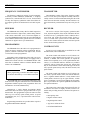
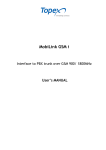
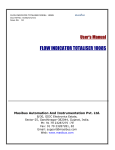
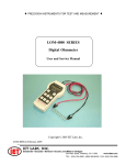
LBI-31564A Mobile Communications DELTA - SX 136 - 174 MHz RADIO COMBINATIONS (NEGATIVE GROUND ONLY) Maintenance Manual LBI-31564 TABLE OF CONTENTS MILITARY AND SYSTEM SPECIFICATIONS . . . . . . . . . . . . . . . . . . . . . . . . . . . . . . . . . 2-3 COMBINATION NOMENCLATURE . . . . . . . . . . . . . . . . . . . . . . . . . . . . . . . . . . . . . . 4 STRUCTURED OPTIONS . . . . . . . . . . . . . . . . . . . . . . . . . . . . . . . . . . . . . . . . . . . . 6 DESCRIPTION . . . . . . . . . . . . . . . . . . . . . . . . . . . . . . . . . . . . . . . . . . . . . . . . . . 5 INITIAL ADJUSTMENT . . . . . . . . . . . . . . . . . . . . . . . . . . . . . . . . . . . . . . . . . . . . . 7 OPERATION . . . . . . . . . . . . . . . . . . . . . . . . . . . . . . . . . . . . . . . . . . . . . . . . . . . 7-8 MAINTENANCE . . . . . . . . . . . . . . . . . . . . . . . . . . . . . . . . . . . . . . . . . . . . . . . . . 8 ILLUSTRATIONS: Figure 1 - Typical Module Layout . . . . . . . . . . . . . . . . . . . . . . . . . . . . . . . . . . . . . . . . 5 SYSTEM SPECIFICATIONS* FREQUENCY RANGE 136-174 MHz FREQUENCY CAPACITY 1, 8, 16 or 32 channels CHANNEL GUARD 33 EIA Tones, 83 Digita1 Codes FREQUENCY STABILITY ±0.0005% or optional ±0.0002% TEMPERATURE RANGE -30C (-22F) to +60C (140E) DUTY CYCLE 100% Receive, 20% Transmit (EIA) BATTERY VOLTAGE Transmit Receive 13.4 VDC +20% 13.8 VDC +20% BATTERY DRAIN (Maximum) Receive Squelched Unsquelched Transmit 40 Watts 60 Watts 110 Watts 0.7 Amperes 2.2 Amperes 12.0 Amperes at 13.6 Volts 17.0 Amperes at 13.6 Volts 27.0 Amperes at 13.4 Volts WARNING Although the highest DC voltage in Mobile Two-Way Radio equipment is supplied by the vehicle battery, high currents may be drawn under short circuit conditions. These currents can possibly heat objects such as tools, rings, watchbands, etc., enough to cause burns. Be careful when working near energized circuits! High-level RF energy in the transmitter Power Amplifier assembly can cause RF burns upon contact. Keep away from these circuits when the transmitter is energized! Copyright© February 1986, General Electric Company 2 LBI-31564 SYSTEM SPECIFICATIONS* - Cont. DIMENSION, LESS ACCESSORIES (H X W X D) 40-60 Watts 110 Watts WEIGHT, LESS ACCESSORIES 40 and 6O Watts 110 Watts 65 mm X 260 mm X 325 mm (2.5 X 10.2 X 12.7 inches) 65 mm X 290 mm X 325 mm (2.5 X 11.4 X 12.7 inches) 5.9 kg (13.0 pounds) 6.5 kg (14.5 pounds) TRANSMITTER CONDUCTED SPURIOUS - 85 dB MODULATION ± 5.0 KHz AUDIO SENSITIVITY 60 to 120 Millivolts AUDIO FREQUENCY CHARACTERISTICS Within +1 dB to -4.5 dB of a 6 dB/octave pre-emphasis from 300 to 3000 Hz per EIA standards. Post limiter filter per FCC and EIA DISTORTION Less than 2% (1000 Hz) Less than 5% (300 to 3000 Hz) DEVIATION SYMMETRY MAXIMUM FREQUENCY SEPARATION 136-153 MHz 150.8-174 MHz RECEIVER AUDIO OUTPUT (to 4.0 ohm speaker) 12 Watts with less than 3% distortion SENSITIVITY Standard UHS Preamp 0.35 uV 0.50 uV 0.25 uV 0.175 uV 0.25 uV 0.125 uV 12 dB SINAD (EIA) Method 20 dB Quieting Method Squelch <6 dB SINAD Channel Guard 8 dB SINAD ADJACENT CHANNEL SELECTIVITY EIA Two-Signal Method ( @ 25 kHz channels) - 85 dB ( @ 30 kHz channels) - 95 dB - 85 dB - 95 dB SPURIOUS RESPONSE - 90 dB - 90 dB INTERMODULATION @ 25/30 kHz - 85 dB - 80 dB 0.5 kHz maximum 17 MHz 23.2 MHz MICROPHONE LOAD IMPEDANCE 600 ohms POWER ADJUST RANGE 2:1 of rated power RF OUTPUT IMPEDANCE 50 ohms FM NOISE - 65 dB CARRIER ATTACK TIME 25 milliseconds AUDIO ATTACK TIME CHANNEL GUARD TX TONE DISTORTION MODULATION ACCEPTANCE ± 7.0 kHz MAXIMUM FREQUENCY SEPARATION 136 - 153 MHz 150.8 - 174 MHz 17 MHz 23.2 MHz FREQUENCY RESPONSE Within +2 and -8 dB of a standard 6 dB per octave de-emphasis curve from 300 to 3000 Hz (1000 Hz reference) 25 milliseconds RF INPUT IMPEDANCE 50 ohms <5% HUM/NOISE RATIO UNSQUELCHED SQUELCHED - 55 dB - 70 dB RECEIVER RECOVERY TIME 200 milliseconds RECEIVER ATTACK TIME 150 milliseconds CHANNEL SPACING 25/30 kHz CHANNEL GUARD (Optional) Tone Digital 67 - 210.7 Hz ( ± 0.5%) ** 023 - 526 (H) code (Standard Codes) * These specifications are intended primarily for use of the serviceman. Refer to the appropriate Specifications Sheet for the complete specifications. ** Any tone (67-210 Hz) ±0.5% 3 LBI-31564 4 LBI-31564 DESCRIPTION General Electric DELTA-SX mobile radio combinations are completely solid state utilizing microcomputer technology and integrated circuits to provide high quality - high reliability radios. The DELTA-SX radio is designed for use in vehicles having a negative ground battery system. In vehicles having a positive ground battery system a polarity converter must be used. Standard combinations may be equipped with: • Microcomputer Control led Frequency Synthesizer • Up to 32 channels • .0002% or .0005% frequency stability • UHS Preamplifier (Ultra High Sensitivity), optional • Tone and/or Digital Channel Guard, optional The radio set is housed in a weather resistant case only 2 1/2 inches high. The radio is secured to the vehicle by a bottom mounting plate, and is tamperproof when locked into the plate. When unlocked, the handle can be pulled down and the radio pulled out of the mounting plate or the top cover removed for servicing. When pulled down, the handle can be used to carry the radio. The PA board is inserted into the radio from the top of the frame, while the TRS board is inserted from the bottom. There are no wires used in the basic radio. Interconnections are provided by pins on the TRS board that mate with connectors on the PA assembly. A power bus connects A+ and A- from the front connector to the PA assembly. The PA board is isolated from ground (floating). power is supplied directly from the battery to the PA power output stage. The radio is of single-layer con-struction with all major modules and tuning adjustments easily accessible from the top of the radio. Centralized metering jacks for the transmitter, receiver and system functions are provided for simplified alignment and troubleshooting. Excluding option boards, the basic radio consists of two printed wiring boards mounted in a cast aluminum frame. The two boards are the transmitter-receiver-system (TRS) board 19D901650G1 and the power amplifier board (See Figure l). The TRS board is connected to chassis ground allowing it to be used in vehicles with a negative ground battery system only. Option boards include the Channel Guard board and VG Interface board. The VG Interface board is used in radios equipped with VOICE GUARD. Figure 1 - Typical Module Layout 5 LBI-31564 FREQUENCY SYNTHESIZER TRANSMITTER The frequency synthesizer consists of a microcomputer, electrically erasable PROM(S) (EEPROM), a frequency synthesizer IC, transmit and receive VCO’s, and associated circuitry. The frequency synthesizer under control of the microcomputer generates all transmit and receive RF frequencies. The transmitter consists of the exciter, frequency synthesizer, TX VCO, and a power amplifier assembly. The PA assembly consists of a PA board mounted along the side of the radio next to the heat sink assembly. The PA board also contains a hermetically sealed antenna relay and a low pass filter. EFEPROM RECEIVER The EEPROM stores binary data for all RF frequencies, Channel Guard tones/ digital codes, and the timing function of the carrier control timer (CCT). The microcomputer accesses the EEPROMS and provides the correct WALSH bits to the Channel Guard board to generate the correct Channel Guard tone or digital code on a per channel basis. The receiver consists of the frequency synthesizer, RX VCO, injection amplifiers, front end, IF and limiter detector. In UHS receivers, a preamplifier board is added in the receiver front end. Audio and squelch circuitry for the receiver is located in the system section of the TRS board. Jacks for the Channel Guard and other structured options are also located in the system area. PROGRAMMING CONTROL UNITS The EEPROM allows the radio to be reprogrammed as needed to adapt to changing system requirements. RF frequencies, Channel Guard tones and digital codes, and the CCT function can be reprogrammed. Depending on the configuration of the radio, one or two EEPROMS may be provided. Radios not equipped with a MODE A/B switch will have one EEPROM. Radios with more than 16 channels and those with the MODE switch will have two EEPROMS. NOTE When programming, remember that all RF frequencies must be divisable by 5 or 6.25 kHz but not both. The EEPROMS can be reprogrammed through the radio front connector using the General Electric Universal PROM Programmer Model TQ23IO. This programmer allows all information to be loaded simultaneously. Alternatively, a single channel Programmer Model 4EX22A10 allows the user to reprogram the radio on a per channel basis. This programmer requires the removal of the radio top cover and any option boards present. A special programming jack, J711, is provided in the radio for interconnections. Programming instructions are provided in the respective Programmer Maintenance Manuals. Several "S" series control units are available for use with the DELTA-SX, radio combinations. The S-500 control unit contains an on-off volume control switch, a rotary channel selector switch for 1, 8, or 16 channels, a MODE A/B switch (optional) to expand the channel select capability to 32, seven segment channel indicators(s), a red transmit indicator, channel busy indicator (optional), and an external tone option jack. Options that may be used with this control unit include Type 90 and 99 tone, squelch operated relay SOR, GE-STAR encoder, and public address. The S-600 control unit contains an on-off volume control switch, squelch disable switch, red transmit indicator, and a 7 segment channel indicator. A rotary channel select switch permits selection of up to eight- channels. A white power on indicator is used for back lighting the front panel. Space is provided for two optional. pushbutton switches and two optional indicators. The S-900 series control units designed specific-ally for the DELTA class radios are highly versatile, software controlled units providing numerous functions and options including: • Dual priority Scan • Digita1 Volume Control • Digital Squelch Control • Type 90 or 99 Encode Tones • GE-STAR Identification 6 LBI-31564 • 128 Channels in 8 Modes of 16 Channels each or 4 Modes of 32 Channels each • Carrier Control Timer (per mode basis)* • Channel Guard - Tone or Digital* • Channel Frequencies* • Home Channel Revert • Auxiliary Relay Control HOOKSWITCHES In Channel Guard or other tone applications, a microphone or handset hookswitch is supplied with the radio. The hookswitches are equipped with a Channel Guard disable switch. Placing the switch in the "up" position (towards the small speaker symbol) disables the Channel Guard decoder. With the switch in the "down" position, the Channel Guard is disabled when the microphone or handset is removed from the hookswitch. CHANNEL SELECTION SPEAKER Depending on the control unit used a single rotary or pushbutton selector switch will select up to 16 channels. In radios equipped with more than 16 channels, the control unit contains a MODE A/B switch. The MODE switch allows the user to select a second set of 16 channels (17-32). A three by five-inch speaker contained in a molded plastic housing provides an audio output of 12 watts with a speaker impedance of four ohms. The speaker leads are terminated in Vehicle Systems Plug P3 which connects to Jl-A on the rear of the control unit. The MODE A/B switch may be used to provide mobileto-mobile communications through an intermediate repeater (repeated path) or direct mobile-to-mobile communications. For example: channel 1 Mode A may be programmed for the repeater frequency (repeated path) while channel l Mode B would be programmed for the mobile receive frequency (direct path). Judicious programming will allow selection of repeated or direct communications paths on selected channels. MICROPHONE AND HANDSET A hand held microphone with a built-in transistorized microphone preamplifier is available for use with the radio. The microphone is housed in a sturdy twopiece case, and the extendable coiled cord plugs into the microphone jack at the k of the control unit. The plug is secured to the jack by a retaining screw. INITIAL ADJUSTMENT After the radio has been installed (as described in the Installation Manual), the following adjustments should be made by a certified electronics technician. TRANSMITTER ADJUSTMENT The transmitter adjustments include measuring the forward and reflected power and optimizing the antenna length, then setting the transmitter to rated power output. Next, measuring the frequency and modulation and recording these measurements for future reference. For the complete transmitter adjustment, refer to the Alignment Procedure in the service section of this manual. RECEIVER ADJUSTMENT An optional telephone-type hand set is available for use with the radio. The handset uses a dynamic microphone with a built-in microphone preamplifier. The extendable coiled cord plugs into the microphone jack on the back of the control unit, and is secured to the jack by a retaining screw. The initial adjustment for the receiver includes tuning the input circuit to match the antenna. Refer to the Front End Alignment Procedures in the service section of this manual. OPERATION * These functions are actually performed in the radio. If you down-load, the data is stored in the control unit. Complete operating instructions for the Two-Way Radio are provided in the Operator’s Manual. The basic procedures for receiving and transmitting messages in mobile combinations are as follows: 7 LBI-31564 TO RECEIVE A MESSAGE 1. Turn the radio on by turning the OFF-VOLUME control halfway to the right. 2. Turn the SQUELCH control clock-wise (to the right) as far as possible. A noise will be heard from the speaker. 3. Adjust the VOLUME control for the desired listening level. 4. Turn the SQUELCH control counterclockwise to the left until the noise just cuts off. 4. Press the push-to-Talk (PTT) switch on the microphone and send the message. The red transmit light on the control unit will glow each time the PTT switch is pressed. MAINTENANCE The use of microcomputer technology allows self diagnostic maintenance routines to be incorporated in the microcomputer software. These routines are easy to run and provide a quick analysis of microcomputer and frequency synthesizer operation. 5. In multi-frequency radios, select the desired channel. The radio is now operational. The service section of this manual contains the diagnostic routines, and other maintenance information to service this radio. The service section includes: TO TRANSMIT A MESSAGE • System interconnections 1. Turn the radio on and select the proper channel. • Mechanical layout 2. If a lengthy message (or several messages) are to be sent, the vehicle engine should be running to maintain the battery charge. 3. Pick up the microphone and listen briefly to the speaker to make sure that no one else is using the channel. • Disassembly procedures • Replacement of IC’s chip capacitors and resistors • Microcomputer self diagnostics • Alignment procedures for the transmitter and receiver • Troubleshooting flowcharts and waveforms Pinted in U.S.A. 8