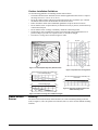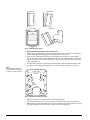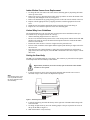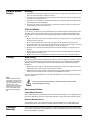
1
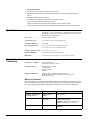
) ,QGRRU2XWGRRU3,50RWLRQ 6HQVRUV *(,QWHUORJL[ ,QVWDOODWLRQ,QVWUXFWLRQV ZZZ*(,QWHUORJL[6HFXULW\FRP Product Summary 'RFXPHQW1XPEHU5HY( 1RYHPEHU A passive-infrared (PIR) motion sensor detects movement within a specific area by sensing the infrared energy emitted from a body as it moves across the sensor’s field of view. When this motion is detected, the sensor transmits an alarm signal to the control panel. Use the indoor motion sensor to protect locations where door/window sensors are impractical or not needed. For example, use a motion sensor to protect large areas or open floor plans. Motion sensors also provide backup protection for door/window sensors. Use the outdoor motion sensor to identify motion in a protected outdoor area. Detected motion in this protected area can sound chimes or turn on outside lights. . Model Nos. 60-639-95R 60-639-95R-OD 60-639-43-EUR 60-639-43-EUR-OD Installation Note Do not use outdoor motion sensors for intrusion protection. The wireless motion sensor includes the following features: • • • • • • • 35 feet by 40 feet coverage area for standard and optional animal alley lenses Masking kit provided to block portions of the coverage area Three minute transmitter lockout time after an alarm, helping to extend battery life Cover-activated tamper (optional wall-activated tamper is included) Supervisory signals transmitted every 64 minutes to the control panel Sensor low battery reports (trouble) to the control panel Field-selectable sensitivity options Indoor Installation Guidelines Use the following guidelines for installing indoor motion sensors. • • • • • • • • • • • If possible, locate sensors within 100 feet of the panel. While a transmitter may have a range of 500 feet or more out in the open, the environment at the installation site can have a significant effect on transmitter range. Sometimes a change in sensor location can help overcome adverse wireless conditions. The recommended mounting height is 7 1/2 feet, but the sensor can be mounted from 5 to 8 feet high in the corner of the area you want to protect. See the animal alley lens guidelines for mounting the optional animal alley lens. Higher mounting provides better range (up to 35 feet), and lower mounting provides better protection close to the motion sensor (see Figures 2 and 3). The optional swivel mount (part #60-737) can be used for difficult mounting locations. Position the sensor to protect an area where an intruder would be most likely to walk across the detection pattern (see Figure 1). Mount the motion sensor on a rigid surface which is free from vibrations. Do not aim the sensor at windows, fireplaces, air conditioners, area heaters, forced air heating vents, or place it in direct sunlight. Sudden changes in temperature may trigger a false alarm from these devices. Do not mount the sensor near duct work or other large metallic surfaces which may affect the RF signals (see RF Testing). Actual acceptable transmitter range should be verified for each installation. Mount the sensor permanently on a flat wall or in a corner. Do not set it on a shelf. Windows should be closed in any area which has an armed motion sensor. A pet will trigger a motion sensor. See animal alley lens guidelines to use a motion sensor when pets are present. Mount the motion sensor on an insulated, outside wall facing in. Position the sensor so it faces a solid reference point, like a wall. 1 Outdoor Installation Guidelines Use the following guidelines for installing outdoor motion sensors. • • • • • • • The outdoor motion sensor should be used for outdoor applications where there’s a temperature range from 10° to 120° F (12° to 49° C). Do not use outdoor motion sensors for intrusion protection since any human, pet, or heated mechanical motion such as an automobile can activate the sensor. Follow the indoor motion sensor installation guidelines except for the last four items. Do not aim the sensor at objects that may be heated excessively by the sun, such as black top or dark colored objects. Do not aim the sensor at foliage or shrubbery which has a dark background. The housing is water-resistant but not water-proof. Mount the sensor underneath eaves or porch coverings to prevent over exposure to rain, ice, and direct sunlight. The sensor’s coverage area is shown in Figures 2 and 4. 0m 20 ft Top View 11 m 6m 10 ft 3m 0 ft 0m 20 ft 3m Person walking across detection path 20 ft 0 ft 6m 35 ft Figure 1. Overhead (Bird’s Eye View) Detection Path Figure 2. Top View Lens Coverage Area SIDE VIEWS (Indoor Motion Sensor Standard Lens) 0m 8 ft 7 1/2 Foot Mounting Height 4 ft 11 ft 2.4 m Side View Indoor Motion Sensor Animal Alley Lens Flush Mount 1.2 m 0m 35 ft 0 ft 0 ft 0m 8 ft 1.2 m 4 ft 0m 8 ft 5 Foot Mounting Height 11 ft 2.4 m 0 ft 4 ft 0 ft 0 ft 1.2 m 11 ft 2.4 m 0m 35 ft Figure 4. Side View of Indoor/Outdoor PIR with Animal Alley Lens 0m 35 ft Figure 3. Side View Coverage Area at Different Heights Indoor Motion Sensor 2 Mounting The sensor can be flush-mounted, incline-mounted, or corner-mounted depending on the lens used (see Figure 5). Also, the optional swivel mount (#60-737) can be used for difficult mounting locations. Indoor/Outdoor PIR Motion Sensors Installation Instructions Flush Mount Inclined Mount Corner Mount Swivel Mount Figure 5. Wall Mounting Options ¾ Use the following procedure to mount the sensor. 1. Remove the mounting plate by depressing the button on the top of the sensor body. With the opposite hand pull the mounting plate away from the body of the sensor. 2. Punch out the mounting holes that best fit your application. See Figure 5 for wall mount options. See Figure 6 to determine which knockouts to use when mounting the motion sensor. Use the lower-side holes for corner mounting, or the lower-back holes for surface mounting with the standard lens. 3. For applications with pets, use the upper mounting holes and the optional animal alley lens. 4. If you desire wall-tamper functionality, remove the wall-tamper knockout (see Figure 6). Note The wall-tamper switch cannot be used when the sensor is swivel or corner mounted. Use With Animal Alley Lens Wall Tamper Knockout Use With Standard Lens Figure 6. PIR Mounting Plate Knockouts 5. Mark the location of the required holes on the mounting surface. 6. Use wall anchors and screws to secure into place. Attach the sensor to the mounting plate. 7. When testing is completed the PIR can be securely attached to its mounting plate by screwing the smallest enclosed screw into the hole at the top of the mounting plate. Indoor/Outdoor PIR Motion Sensors Installation Instructions 3 Indoor Motion Sensor Lens Replacement 1. To change the lens, first remove the sensor from its mounting plate by depressing the button on the top of the sensor. 2. Remove the cover by depressing the two tabs on the top and the one tab on the bottom of the sensor body and sliding the cover off (see Figure 8). 3. Remove the installed lens by gently placing pressure on the lens from the outside of the lens. 4. Replace with the appropriate lens by aligning its notches with the appropriate tabs in the cover. 5. Install the new lens with the smooth side facing out and the grooved side facing in. 6. Replace the cover and then replace the sensor in its mounting plate. Animal Alley Lens Guidelines The optional animal alley lens (part #60-709) provides protection in installations where pets move about freely. See Figures 2 and 4 for coverage. • • • • • Allowed mounting height is between 3 and 5 feet. Be sure to use the flush-mount position or the corner mount position with the back of the PIR parallel to the walls. Do not use the inclined mount position since this would tilt the PIR’s field of view downward. Position the sensor to have a clear line of sight across the protected room. For best results, install the sensor higher than the highest point that the pet might reach in the detection area. If the detection area contains furniture or other objects upon which the pet could climb or jump, either remove these objects, mount the PIR a safe distance above these objects, or mask these areas. Setting the Sensitivity The PIR is set to standard sensitivity at the factory. This sensitivity is preferred for most applications and provides the best immunity to false alarms. ! High sensitivity should only be used in extremely quiet environments where thermal transients are not expected. Caution 1. Locate the sensitivity pins by first removing the mounting plate and the sensor cover as described in steps 1 and 2 of the Lens Replacement process. Note If the shorting jumper is not used or placed incorrectly, the sensor defaults to standard sensitivity. STANDARD HIGH Figure 7. Sensitivity Pins Locations 2. Locate the sensitivity pins under the battery on the right side of the PIR when looking at the front of the PIR. 3. To change to high sensitivity, move the shorting jumper to the pair of pins that are closer to the top of the PIR (see Figure 7). 4. Walk test the PIR to verify sensitivity. 4 Indoor/Outdoor PIR Motion Sensors Installation Instructions Outdoor Motion Sensor Mounting 1. Determine the desired mounting location for the sensor leaving at least four inches of room above the wall mount plate to attach the sensor. 2. Using the screws and anchors supplied, attach the wall mount plate with the opening for the swivel mount facing downward. 3. Attach the sensor assembly to the wall mount plate by screwing the sensor assembly up into the opening in the wall mount plate. 4. To remove the sensor for testing or battery replacement, slide the front cover of the sensor upward until the sensor can be removed. Filter Installation A one inch by one inch piece of lens material has been included with the outdoor motion sensor. The filter reduces the sensors sensitivity to white light sources (sunlight and head lights) and infrared sources. Install the filter when experiencing unwanted sensor activations due to these sources. 1. Remove the sensor from its water resistant enclosure by sliding the front cover upward until the sensor can be removed. 2. Remove the mounting plate of the sensor by depressing the button on top of the sensor. 3. Remove the front cover of the sensor by depressing the two tabs on the top and the one tab on the bottom of the sensor body and sliding the cover off (see Figure 8) 4. Place the sensor on its back and drop the filter into the lens chamber covering the sensor’s detector. 5. Replace the cover, making sure the filter remains in the lens chamber and does not interfere with the attachment of the cover. 6. Replace the sensor’s mounting plate and install the sensor in its water resistant enclosure. Testing Walk Testing Walk testing should be done to determine the sensor’s actual coverage area. The edge of the coverage pattern is determined by the first flash of the LED. This may change slightly depending upon the sensitivity setting. Walk test the unit from both directions to determine the pattern boundaries. 1. Remove the sensor body from the mounted mounting plate, activate the tamper switch, and remount the body to activate the 60 second walk test mode. 2. Walk across the coverage pattern to determine the coverage area, indicated by LED activation. Each activation extends the walk test mode for an additional 60 seconds. After 60 seconds without motion the walk test mode and the LED will no longer activate when motion is detected. Note When the walk test mode has ended, an alarm can be transmitted only after 3 minutes have passed since the previous alarm. This 3 minute lockout time reduces unnecessary RF transmissions in high traffic areas thereby extending battery life. ! Excessive use of the walk test mode may reduce battery life. Use only for initial setup and maintenance testing. Caution Environment Testing Indoor Motion Sensors Turn on all heating or air conditioning sources which would normally be active during the protection period. Stand away from the sensor and outside the coverage pattern and watch for alarms. Outdoor Motion Sensors Verify that the sensor’s coverage area does not extend into undesired areas that might cause unwanted activations. These areas may include undesired human, pet, or automobile motion. Coverage Masking After walk testing and environment testing are completed, masking labels can be applied to the sensor’s lens to block detection of problem areas. The masking labels provided are cut to match the corresponding lens segments. Indoor/Outdoor PIR Motion Sensors Installation Instructions 5 1. Determine which detection zone/lens segment needs a masking label. 2. Peel the desired mask label from its backing and apply to the inside of the lens segment to be blocked. Programming Refer to the panel installation instructions for information on programming the sensor into the panel. Final Testing Final testing should be done to verify radio signal integrity and confirm control panel programming and response. The actual transmitter range can be determined by performing a sensor test as follows: 1. After the sensor has been mounted, remove it from its mounting plate and activate the tamper switch to start the walk test mode. 2. Replace the sensor in its mounting plate. 3. Place the control panel in test mode. Move across the detection pattern until the sensor’s LED turns on. STOP your motion. 4. Listen for the appropriate system response. If the system does not respond, proceed to the “Troubleshooting” section. Maintenance At least once a year, the range and coverage should be verified for proper operation. The end user should be instructed to put the sensor in walk test mode and walk through the far end of the coverage pattern to verify proper detection. Replacing Batteries When battery replacement is necessary, observe proper polarity (as shown in the battery compartment) when installing the new battery. The sensor may be damaged if installed incorrectly. As you look at the battery compartment, on the left side the positive battery end is down and on the right side the positive end is up. When the battery is replaced, wait at least 3 minutes after installing the battery before activating the walk test mode. See Figure 8 for battery locations. ! Replace only with two AA 1.5V Alkaline batteries. Dispose of used batteries according to manufacturer’s instructions and local government authorities. Caution 2 AA Batt 1.5 Vol eries t PIR Cover PWB Cover Lens Tabs Sensor Body Tamper Switch Mounting Plate Figure 8. PIR Components Troubleshooting Follow these guidelines if the system does not respond correctly when the sensor is activated. • • 6 Check programming and re-program sensor into panel if necessary. Move the sensor to another location and test for correct response. Indoor/Outdoor PIR Motion Sensors Installation Instructions ¾ To relocate a sensor: 1. Test the sensor a few inches from the original position. 2. Increase the distance from the original position and retest until an acceptable location is found. 3. Mount the sensor in the new location. 4. If no location is acceptable, test the sensor as described below: Test a known good sensor at the same location. If the system does not respond, avoid mounting a sensor at that location. If the replacement sensor functions, return the problem sensor for repair or replacement. Specifications Compatibility: ..........................Concord™, Concord Express, International Concord, Simon®, Euro Simon, Quik Bridge®, 1 & 2 Channel Receiver, Quik Bridge Euro Repeater SAW, Quik Bridge International Loop Receiver, SuperBus®, 2000 RF Receiver, SuperBus 2000 433 MHz Receiver Power source: ...........................2 AA 1.5V alkaline batteries Typical battery life: .................2-4 years at 68° F (20° C) not verified by UL Transmitter Frequency: ..........319.5 MHz Operating temperature: ..........32° to 120° F (0° to 49° C) Indoor Motion Sensor 10° to 120° F (12° to 49° C) Outdoor Motion Storage temperature range: ....-30° to 140° F (-34° to 60° C) Maximum Humidity ................90% Relative Humidity non-condensing Dimensions: ..............................2.9 in. (7.3cm) x 2.4 in. (6 cm) x 1.9 in. (4.8 cm) (L x W x H) Declaration of Conformity Manufacturer’s Name: ............GE Interlogix Manufacturer’s Address: ........2266 North 2nd Street North St. Paul, MN, USA 55109 EU Representative:..................Interlogix Europe & Africa Excelsiorlaan 28 B-1930 Zaventum Belgium Product Identification: ............Product: Indoor and Outdoor PIR Motion Sensors Model Numbers: 60-639-43-EUR and 60-639-43-EUR-OD Brand: GE Interlogix Means of Conformity We declare under our sole responsibility that this product is in conformity with Directive 93/68/ EEC (CE Marking) and complies to the essential requirements of 1999/5/EC (R&TTE) based on test results using (non)-harmonized standards in accordance with the Directives mentioned. Concerning R&TTE A sample of the product has been tested by: Mikes Product Service KTL Arnhem Standards used: I-ETS 300 220 (10.1993) EN50130-4 (1995) EN50130-4/A1 (1998) EN60950, 1992 (A1, A2, A3, A4, A11) IEC950, 2nd ed. (A1, A2, A3, A4) Test report: T14152-1-02SM 98639220 98639250 Indoor/Outdoor PIR Motion Sensors Installation Instructions 7 Notices Approved for use in the countries marked with a check (9). (9) Austria (9) Germany () Liechtenstein (9) Portugal () Belgium () Greece () Luxembourg (9) Spain (9) Denmark () Iceland (9) Netherlands (9) Sweden () Finland (9) Ireland () Norway () Switzerland (9) France (9) Italy () Poland () United Kingdom ) *(,QWHUORJL[4XLN%ULGJH6LPRQDQG6XSHU%XVDUHUHJLVWHUHGWUDGHPDUNV RI*(,QWHUORJL[&RQFRUGLVDWUDGHPDUNRI*(,QWHUORJL[$OORWKHUWUDGHPDUNVDUH SURSHUW\RIWKHLURZQHUV $OOULJKWVUHVHUYHG 8 *(,QWHUORJL[ 6HFRQG6WUHHW1RUWK 1RUWK6DLQW3DXO01 7HFKQLFDO6XSSRUW Indoor/Outdoor PIR Motion Sensors Installation Instructions