1
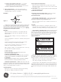
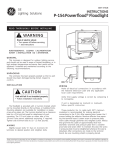
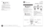
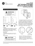
g
GE
Lighting Solutions
GEH-3902H
INSTRUCTIONS
PF-400 Powerflood® Floodlight,
Glarefighter™ Powerflood®
and Turnpike™ Luminaire
®
READ THOROUGHLY BEFORE INSTALLING
Figure 1
WARNING
Risk of electric shock
• Turn power off before servicing
– see instructions
GENERAL
This luminaire is designed for outdoor lighting applications,
and should not be used in areas of limited ventilation, or in high
ambient temperature enclosures. Best results will be obtained if
installed and maintained according to the following recommendations.
UNPACKING
This luminaire has been properly packed so that no parts
should have been damaged during transit. Inspect to confirm.
MOUNTING
CAUTION
Unit will fall if not installed properly
• Follow installation instructions
This floodlight is provided with either trunnion mounting,
pipe mounting, or wall mounting.
NOTE: The unit may be mounted to point from straight up to
straight down but in no case may the ballast be located
above the optical. To mount from overhead structures, use
the top trunnion option.
NOTE: For aimed-up application, remove two screws from
rear bottom corners of back housing and reinstall them in
front housing rear bottom corners.
1. TRUNNION MOUNTED UNITS — Mounted directly on a flat
surface. Mounting adapters are available for installation on
poles, cross-arms, pipes, etc.
The trunnion bracket has a clearance hole for a 3/4-inch bolt
used for attachment to such mountings. The 3/8-inch holes on
either side permit additional anchoring, where required.
Tighten side trunnion bolts to 50 -55 foot pounds.
2. A. NORMAL PIPE MOUNTED UNITS (2G) — The slipfitter
can be mounted on 1-7/8-inch O.D. through
2-3/8-inch O.D. or 2-7/8-inch O.D. through 3-inch
O.D. pipes. Three set screws are used to clamp the
floodlight securely to the pipe. Tighten set screws to
18 -22 foot pounds.
These instructions do not purport to cover all details or variations in equipment nor to provide for every possible contingency to be met in connection with installation, operation or
maintenance. Should further information be desired or should particular problems arise which are not covered sufficiently for the purchaser’s purposes, the matter should be referred
to GE Lighting Solutions.
B. SPECIAL PIPE MOUNTED UNITS (3G) — For bridge/
overpass applications custom factory modification
required. Same as above except with three jam nuts and
set screws. Tightened to 55-65 foot-pounds.
2. Remove protective insulation shield.
NOTE: On units provided with the ”power tray’’ option,
disconnect the two plugs on the top of tray. Loosen screws
and remove tray.
3. WALL MOUNTED UNITS — The wall mounting plate is
provided with four (4) 0.438-inch clearance holes spaced
4.375(H)x2.875(V) inches for mounting.
3. Insert cable through compression plate and rubber bushing and
secure by tightening screw.
4. Make electrical connections.
AIMING
5. Reposition protective insulation shield. (If power tray, connect
both plugs on top of tray after securing the tray.)
6. Close and secure door.
FRONT OF SIGHT
TARGET
PIPE AND WALL MOUNTED UNITS — Open wiring compartment cover located on the mounting bracket. Make electrical
connections and close wiring compartment cover.
Figure 2
NOTE: For multivolt units refer to “Ballast Connections on
Multivolt Units’’.
REAR OF SIGHT
Located on top of the luminaire, above the door locking screw,
is a “sight-track’’ optical sight for point aiming. Align the front
and rear sights so that they have equal space showing on either
side of the groove and the target centered in the groove. Sighting
is not performed on the Turnpike™ luminaire.
LAMPS
WIRING
Lamp Tightness – Mogul Base Lamp: The lamp should be securely
inserted to the NEMA-EEI specified torque of 35 inch-pounds,
which is best achieved by very firmly tightening to insure application of sufficient torque. Tightening must be sufficient to fully
depress and load the center contact of the socket.
Make all electrical connections in accordance with the
National Electrical Code and any applicable local code
requirements.
Verify that supply voltage is correct by comparing it to
nameplate.
Use only lamps specified on nameplate. Observe lamp
manufacturer’s recommendations and restrictions on lamp
operation, particularly ballast type, burning position, etc.
MAINTENANCE
CAUTION
If unit is designated as multivolt or multiwatt, follow specific
instruction.
Connect ground lead to the green lead, green ground
screw on housing or terminal block provided.
Risk of burn
• Allow lamp/fixture to cool before
handling
Do not remove insulated connectors from wires not
needed for required voltage connection.
WARNING
When changing voltage on reconnectable units, move only
the lead with the insulated connector.
IF SINGLE VOLTAGE:
All single voltage ballasts are pre-wired such that user need
only connect the supply conductors.
IF MULTIVOLT: (120/208/240/277 volts)
Connect the ballast lead with the insulated terminal to the desired
voltage terminal as indicated on the ballast terminal nameplate.
IF MULTIWATT:
Multiwatt ballasts are available in various combinations of wattage.
See wiring instructions on wiring tag inside the luminaire.
TRUNNION MOUNTED UNITS — NOTE: Cable strain relief and
sealing are provided by the compression plate and rubber bushing
supplied for 9/16-inch O.D. cable. Three-conductor, AWG No. 14
cable is recommended. (Refer to Figure 1.)
1. Open the glass door.
Risk of burn
• Do not touch operating luminaire
Periodic cleaning on the outside of the door glass will ensure
operation at maximum optical efficiency. The glass and reflector
(if needed) should be cleaned with non-abrasive soap, cleaner, or
detergent solutions, rinsed with cold water and wiped dry.
NOTE: Door may be removed by opening approximately
190°, lifting up slightly and sliding to the right.
The light output is also dependent on the age of the lamp. In
applications where the light level is critical, it may be desirable to
replace lamps before they burn out. The lamp manufacturer can
provide data showing how the lamp light output decreases with
use.
NOTE: Door may be removed by opening approximately
190°, lifting up slightly and sliding to the right.
g
GE Lighting Solutions • 1-888-MY-GE-LED • www.gelightingsolutions.com
1-88 8 - 6 9 - 4 3 -5 3 3
GE Lighting Solutions is a subsidiary of the General Electric Company. Evolve and other trademarks belong to GE Lighting Solutions. The GE brand and logo are trademarks of the General Electric Company.
© 2011 GE Lighting Solutions. Information provided is subject to change without notice. All values are design or typical values when measured under laboratory conditions.
35-201578-E3 (3/04)