1
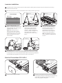
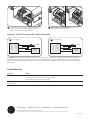
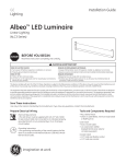
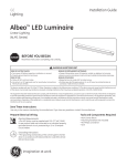
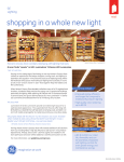
Installation Guide
GE
Lighting Solutions
Albeo LED Luminaire
TM
Modular High & Low Bay Lighting
ABHG-Series CE
BEFORE YOU BEGIN
Read these instructions completely and carefully.
Save These Instructions
Use only in the manner intended by the manufacturer.
If you have any questions, contact the manufacturer.
Prepare Electrical Wiring
Electrical Requirements
• The LED luminaire must be connected to the mains supply according to its ratings on the product label.
• Use an input cord with 3 conductors each with a cross-section between 1,5mm2 and 2,5mm2 of type HD-21 or HD-22.
• Suitable for use indoors.
Grounding Instructions
• The grounding and bonding of the overall system shall be done in accordance to local electric code of the country where the luminaire is installed.
imagination at work
WARNING
RISK OF ELECTRIC SHOCK
• Turn power off before inspection, installation
or removal.
• Properly ground electrical enclosure.
RISK OF FIRE
• Follow all local codes.
• Use only IEC approved wire for input/output connections. Minimum size 18 AWG (0,75mm2).
Luminaire Installation
1
Carefully unpack unit and properly inspect for defects before installing. Wear work gloves to prevent dirt and oil from being
transferred to the luminaire.
2
Select the appropriate mounting method based on the ordering number logic chosen.
Attach to
structural member
Fixture Weight
ABHG-series
LED Modules
1 module
2 modules
3 modules
4 modules
3
Rod mount
bracket
6
Mounting
inserts
Max. Weight
5,9 kg
7,7 kg
14,1 kg
16,4 kg
Chain or Cable Mounting: Please
follow local codes and minimum load
rating guidelines when selecting and
installing a cable or chain.
NOTE: When selecting chain, a
joint in a circular chain link shall
be welded. A joint in a chain link of
another shape shall not be located
within 30 degrees of the vertical
unless welded.
Attach to
structural member
Tighten screws
4
Direct Mounting: Hang two chains/
cables from a structural member
of the ceiling. Fixture must be
supported independently of an
outlet box. Tighten adjustment
screws on all four mounting inserts,
then attach chain or cable to
mounting inserts on both ends of
fixture.
Attach to
structural member
5
Indirect Mounting for Uplighting:
Hang two chains/cables from a
structural member of the ceiling.
Fixture must be supported
independently of an outlet box.
Attach chain or cable to eye bolt
mounts on both ends of fixture.
Note: Mounted fixture must have a
minimum distance to lighted objects
of 0,25m.
Fasten
with nuts
Rod Mount Kit: Attach two rod mount brackets to fixture using four 10-32 x 3/8”
pan head screws per bracket. Secure 1/2” threaded rods into structural members
in ceiling. Place a nut on each threaded rod where fixture should hang. Slide fixture
onto threaded rods and tighten second nut onto rods to secure fixture.
Electrical Connections (220–240V~)
For optional
dimming line
AC line
1
Loosen screws to remove endcap.
2
Bring AC line through the first hole on top of the fixture
using supplied cable gland. Optionally, bring the dimming
control wires through the second hole on top of the
fixture using supplied cable gland.
DALI
3
Connect the AC line to the power terminal block as follows:
Brown to L1, Blue to N, and Green/yellow to ground.
Reattach endcap if there is no dimming line.
4
1-10V
Optional DALI and 1-10V Dimming: Follow wiring
diagram below. Reattach endcap.
Optional 1-10V Volt Dimming or DALI Lighting Controller
B
DALI Controller
Line
Neutral
Ground
DALI
DALI
Brown
Blue
Green/Yellow
To AC Main
Violet/White
Violet
1-10V Dimmer
LED Driver
LED Driver
A
To DALI
Controller
Line
Neutral
Ground
1-10V(+)
1-10V(-)
Brown
Blue
Green/Yellow
Violet
Grey
To AC Main
To 1-10V
Dimmer
For Step 4: Follow diagram A for DALI or diagram B for 1-10V. The LED luminaire is pre-programmed for either DALI or
1-10V dimming at the factory. Run wires from controller through a different knockout than the AC input wire. At output
side of LED driver, make appropriate connections to the dimming terminal block. Follow lighting controller installation
instructions.
Troubleshooting
Symptom
Solution
Luminaire will not turn on.
• Check that the color of the supply side wires match the color of the wires they are connected to.
• Check that all wire connectors are properly connected.
• Verify that your input voltage is within specs.
Mounting insert slides
from side to side.
• Check that the mounting insert is properly tightened using the adjustment screws provided.
GE Lighting • 1-888-MY-GE-LED
(1-888-69-43-533)
• www.gelighting.com
The GE brand, logo, and Albeo are trademarks of the General Electric Company.
© 2014 GE. Information provided is subject to change without notice. All values are design or typical values when measured under laboratory conditions.
ALB007-020514