1
GE
Transportation
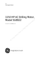
1150 HP AC Drilling Motor,
Model 5GEB22
it on
a
m
r
o
f
n
I
l
Document No. GEK-91696, Rev. D
ia
t
en
id
f
n
o
C
d
r
a
t
n
a
y
r
P
GE
ie
r
op
GEK-91696D
1150 HP AC Drilling Motor, Model 5GEB22
© {2009} General Electric Company. All rights reserved. The information contained in this publication is the property of
General Electric Company and is disclosed in confidence. This publication is intended for use by GE customers solely
for purposes of operating and performing routine maintenance of purchased or licensed GE products, and it shall not
be reproduced, redistributed, retransmitted, translated, abridged, adapted, condensed, revised or otherwise modified, in
any form, in whole or in part, or used for any other purpose, or disclosed to third parties, without the express written
consent of GE.
GE and Customer agree that the information contained herein does not purport to cover all details or variations in GE
products or to provide for every possible contingency with installation, operation or maintenance. Should further information be desired or should particular problems arise that are not covered sufficiently for the user’s purposes, the matter
should be referred to General Electric Company. Any applicable Federal, State or local regulations or company safety or
operating rules must take precedence over any information or instructions given in the Technical Documentation. GE
has no obligation to keep the material up to date after the original publication.
it on
GENERAL ELECTRIC COMPANY EXPLICITLY DISCLAIMS ALL WARRANTIES OF ACCURACY, MERCHANTABILITY OR FITNESS FOR
ANY PURPOSE IN CONNECTION WITH THIS PUBLICATION AND USE THEREOF.
a
m
If you are not an authorized recipient of this publication, you are hereby notified that anyrperusal, use, distribution, copying or disclosure is strictly prohibited. If you have received this publication in error, please
fo immediately return to GE at the
n
I14, 2901 East Lake Rd., Erie, PA 16531.
following address: GE Transportation, Technical Publications Department, Building
l
ia
t
n
e
id
f
n
o
C
d
n
a
y
r
a
t
e
ri
p
ro
P
GE
2
GEK-91696D
1150 HP AC Drilling Motor, Model 5GEB22
CONTENTS
Page
1. GENERAL INFORMATION.......................................................................................................................................................................................... 4
1.1. INTRODUCTION ........................................................................................................................................................................................................... 4
1.2. SAFETY INFORMATION.............................................................................................................................................................................................. 4
1.3. ATEX CERTIFICATION.................................................................................................................................................................................................. 4
1.4. INSTALLATION AND OPERATIONAL INSTRUCTIONS..................................................................................................................................... 5
1.5. MODEL DIFFERENCES............................................................................................................................................................................................... 13
2. CONTROLS AND INDICATORS................................................................................................................................................................................ 13
3. FUNCTIONAL DESCRIPTION ................................................................................................................................................................................... 13
4. SCHEDULED MAINTENANCE.................................................................................................................................................................................. 13
4.1. MONTHLY SCHEDULED MAINTENANCE PROCEDURE................................................................................................................................. 14
4.2. CLEANING THE MOTOR............................................................................................................................................................................................ 16
5. REMOVAL AND REPLACEMENT PROCEDURES ............................................................................................................................................... 16
5.1. MOTOR PREPARATION FOR SHIPMENT.............................................................................................................................................................. 16
5.2. DISASSEMBLY PROCEDURES.................................................................................................................................................................................. 19
5.3. INSPECTION AND REPAIR PROCEDURES .......................................................................................................................................................... 25
5.4. STEAM CLEANING....................................................................................................................................................................................................... 28
5.5. STATIC ELECTRICAL TESTING.................................................................................................................................................................................. 29
5.6. ROTOR SUBASSEMBLY PROCEDURES................................................................................................................................................................ 30
5.7. ROTOR INSTALLATION INTO THE STATOR FRAME ......................................................................................................................................... 35
5.8. MOTOR BEARING CHECKS AFTER ASSEMBLY................................................................................................................................................. 37
5.9. FINAL ASSEMBLY OF ROTOR DRIVE END (DE) COMPONENTS ................................................................................................................ 39
5.10. FINAL ASSEMBLY OF ROTOR CONNECTION END (CE) COMPONENTS.................................................................................................. 39
5.11. ELECTRICAL RUNNING TESTS................................................................................................................................................................................ 39
5.12. HUB INSTALLATION.................................................................................................................................................................................................... 40
6. SUMMARY DATA........................................................................................................................................................................................................... 44
6.1. DRILL MOTOR DATA.................................................................................................................................................................................................... 44
6.2. DRILL MOTOR COMPONENT IDENTIFICATION................................................................................................................................................ 46
6.3. INSPECTION DATA....................................................................................................................................................................................................... 47
6.4. SPECIAL TOOLS AND MATERIALS......................................................................................................................................................................... 47
a
rm
fo
n
lI
it on
ia
t
en
id
f
n
o
C
d
n
a
y
r
a
t
ie
r
op
r
P
GE
3
GEK-91696D
1150 HP AC Drilling Motor, Model 5GEB22
1.
GENERAL INFORMATION
1.1.
INTRODUCTION
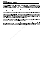
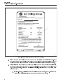
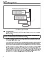
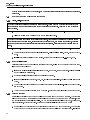
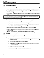
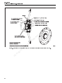
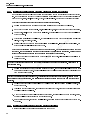
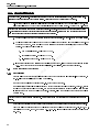
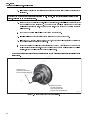
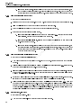
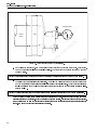
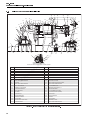
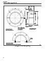
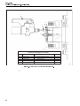
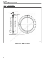
This publication provides basic instructions for inspection, maintenance, and overhaul procedures the drilling
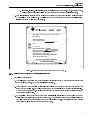
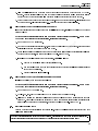
motor model 5GEB22. Figure 1 represents the 5GEB22 motor with cooling blower and connection box. Figure
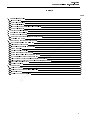
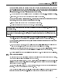
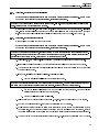
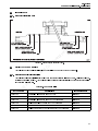
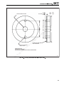
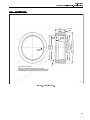
2 depicts the 5GEB22 grounding block and rotor lock for shipment. Also included in this publication are special
tools and materials required to perform the procedures.
For general drilling motor information, refer to Table 9 in section 6.1.2. Drill Motor General Data in this publication.
For drilling motor application data, refer to Table 8 in section 6.1.1. Drill Motor Application Data in this publication.
This publication has significant changes since the last release. Due to major changes, there are no revision bars.
a
rm
fo
n
lI
it on
ia
t
en
id
f
n
o
C
d
1.2.
1.3.
n
a
y Motor with Blower and Connection Box.
Figure 1. 5GEB22 Drilling
r
a
t
SAFETY INFORMATION
e
i
r
p
Safety precautions, which
be observed when working on this equipment, appear throughout this publicaothemustpotential
r
tion. WARNINGS indicate
for personal injury, and CAUTIONS indicate the potential for equipment
P
damage.
GE
ATEX CERTIFICATION
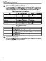
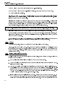
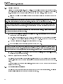
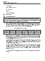
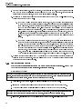
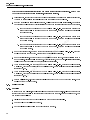
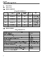
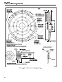
ATEX certification applies only to those motors with the increased safety nameplate shown in Figure 3 .
NOTE: In order to maintain ATEX approval, only GE Transportation original parts shall be used as replacement parts.
Due to format changes, revision bars are not used.
4
GEK-91696D
1150 HP AC Drilling Motor, Model 5GEB22
a
rm
fo
n
lI
it on
ia
t
en
id
f
n
o
C
d
n
a
y
r
a
t
ie
r
op
r
P
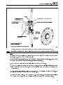
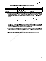
GEAND OPERATIONAL INSTRUCTIONS
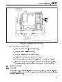
INSTALLATION
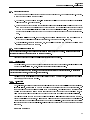
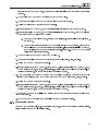
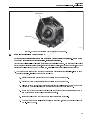
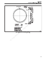
Figure 2. 5GEB22 Drilling Motor Without Cooling Blower or Connection Box.
1.4.
WARNING: Installation shall be in accordance with the instruction as defined in EN 60079–14:2008 “Electrical
apparatus for explosive gas atmospheres, Part14. Electrical installation in hazardous areas (other than mines)".
Guard for couplings, belts, or chains should be installed as needed to protect against accidental contact with
moving parts. Machines accessible to the public should be further guarded by screens, guard rails, etc., to
prevent the public from coming in contact with the equipment. Failure to observe these precautions may result
in injury or death.
1. This machine is suitable for operation in typical oil well drilling industry rig environments including offshore
platforms and mobile drilling units. Use the motor in the correct ATEX category only as indicated in Figure
3 . For other types of applications and environments, please contact your GE representative to determine
suitability.
5
GEK-91696D
1150 HP AC Drilling Motor, Model 5GEB22
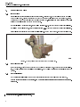
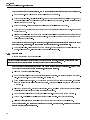
DRILLING MOTOR MODEL NO. – 5GEB22
SERIAL NO.
COOLING–3000 SCFM AIR SUPPLIED
BY BLOWER UNIT
CLOSED COOLING SYSTEM, IP56, TO MAINTAIN MAX.
INTERNAL AIR TEMPERATURE OF 45 C
RATINGS
AMBIENT AIR MAX
PHASE
AC VOLTS (L-L)
AMPS AC
S9
45 C
CONTINUOUS
45 C / 55 C
3
587
1120 / 1048
a
rm
fo
n
lI
1380
it on
RATER RPM
800
SHAFT HP
1400
1150 / 1075
MAX. FREQUENCY HERTZ
153
MAX OPERATING RPM
3000
CONSTANT HP 800–1800 RPM (600 VOLT L–LINE SUPPLY)
WITH 600 VOLTS MAINTAINED ABOVE 820 RPM
CONSTANT HP 800–2400 RPM (690 VOLT L–LINE SUPPLY)
WITH 690 VOLTS MAINTAINED ABOVE 940 RPM
ia
t
en
id
f
n
INSULATING CLASS
CONNECTION
INGRESS PROTECTION
r
a
t
n
a
y
ie
r
op
o
C
d
H
WYE
IP44 / 6424 LBS (2914 Kg)
IP56 / 7124 LBS (3238 Kg)
r
P
GE Figure 3. Safe Electrical Parameters for the 5GEB22 Motor.
E-50984
2. It is the end user’s responsibility to ensure that the motor with steel components including shaft, stator
frame, stator core, and rotor core, along with the blower and variable speed drive are installed in the correct
designated area and will not be subjected to existing (or foreseeable) aggressive destructive substances.
3. Periodic lubrication is not required on model 5GEB22 drilling motor between scheduled overhaul intervals
because the bearings are grease packed and permanently sealed. Motor bearings MUST be replaced after
25,000 hours of operation, which is 90% of calculated bearing life. All maintenance must be carried out in
accordance with:
a. EN 60079–17:2003— Electrical apparatus for explosive gas atmospheres, Part 17. Inspection and
maintenance of electrical installations in hazardous areas (other than mines).
6
GEK-91696D
1150 HP AC Drilling Motor, Model 5GEB22
b. IEC 60079–19:2006 — Electrical apparatus for explosive gas atmospheres, Part 19. Repair and overhaul for apparatus used in explosive atmospheres (other than mines or explosive industry).
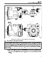
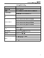
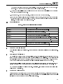
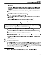
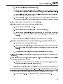
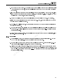
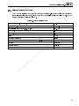
4. Safe electrical parameters are defined in Figure 3 and Figure 4 defines the safe environmental parameters
for the drilling motor model 5GEB22. The drilling motor may be operated in the presence of typical vibration
levels encountered on land and offshore rigs.
CERTIFIED Ex e II T3 (TAMB –40 C to +55 C)
IEC 60034–1
SIRA 09ATEX3077X
Year of Construction
1180
a
rm
fo
n
lI
II 2 G c T3
Motor Model Number: 5GEB22
Maximum Current: 1800
AMPS (RMS)
Ratio Max./Nom. (IA / IN) Current: 1.36
Safe Stall Time: 37 Seconds
Temperature Protection Devices Must Be
Set At 190 C (maximum)
it on
ia
t
en
id
f
n
o
C
d
DO NOT OPEN WHEN ENERGIZED
r
a
t
n
a
y
E-50985
Figure 4. Safe Environmental Parameters for the 5GEB22 Motor.
ie
r
op
1.4.1. Drilling Motor Model 5GEB22 Operational Requirements
r
P
Efitted to the equipment must be capable of withstanding maximum temperatures of 230°F (110°C)
The cable
G
at the cable entry point. No PVC type insulation is permitted.
The drilling motor requires:
1.
2. The equipment must be supplied continuously with at least 3000 Standard Cubic Feet per Minute (SCFM)
(84930 SLPM) of cooling air. The cooling arrangements must be suitable for the area in which it is installed.
When fitted to the equipment, the cooling arrangements must ensure that the equipment satisfies a degree
of protection of at least IP44.
3. RTDs supplied with the motor are to be connected to intrinsically safe circuits to meet compliance of the Ex
certification for operation in a hazardous environment. The protective device must be suitably certified as
compliant with the European Directive 94/9/EC as a Safety Related Device. These circuits are to be manually
reset only and will trip (stop) the motor at 190 °C (374 °F).
7
GEK-91696D
1150 HP AC Drilling Motor, Model 5GEB22
1.4.2. 5GEB22 Motor Equipped with Closed Loop Cooling System
When the motor is equipped with a closed loop cooling system, the cooling arrangement must ensure that the
equipment satisfies a degree of protection of at least IP56. The motor must be used in accordance with the
duties defined in this certificate, with the water cooler supplied with coolant in accordance with Table 2 .
TABLE 2. 5GEB22 CLOSED LOOP COOLING OPTIONS
S1 (continuous)
S1 (continuous)
S9 (Duty A)
S9 (Duty A)
S9 (Duty B)
S9 (Duty B)
S9 (Duty B)
Duty
Minimum Water Flow Rate
100 US gal/min (378.5 liters/min)
50 US gal/min (189.2 liters/min)
100 US gal/min (378.5 liters/min)
50 US gal/min (189.2 liters/min)
100 US gal/min (378.5 liters/min)
88 US gal/min (333.1 liters/min)
50 US gal/min (189.2 liters/min)
TABLE 3. 5GEB22 DUTY CYCLES
Duty Reference
A
B
C
1.4.3.
8
Max. Coolant Temp. (at cooler inlet)
33.0 °C (91.4 °F)
25.0 ºC (77 ºF)
33.0 °C (91.4 °F)
25.0 ºC (77 ºF)
37.7 °C (99.86 °F)
36.0º C (96.8 ºF)
28.0 ºC (82.4 ºF)
a
rm
fo
n
lI
it on
ia
t
en
Specification
120 seconds on at 800 rpm, 1400 HP, 9200 lb/ft torque, followed by 90 seconds on at 80
rpm, no load. (S9 duty)
144 seconds on at 669 rpm, 1150 HP, 9025 lb/ft torque, followed by 116 seconds on at 80
rpm, no load. (S9 duty)
32 seconds on at 800 rpm, 1400 HP, 9200 ft/lb torque, followed by 30 seconds on at 800
rpm, no load. (S9 duty)
id
f
n
o
C
d
n
a
y
r
a
t
Drive Systems Used with the i5GEB22
e
r
The 5GEB22 motor shallo
bepused with one of the drives indicated in Table 4 or as listed in the ATEX certification.
rbe limited to 1800 amps maximum.
The drive outputs shall
P
GE
GEK-91696D
1150 HP AC Drilling Motor, Model 5GEB22
TABLE 4. DRIVE SYSTEM LIST.
MANUFACTURE
GE
Cegelec Bauteil
Unico Inc
MODEL
National Oilwell Varco
AC2000AW Variable Speed Drive
GD3000E AC Drive System
Type 2400 Series (Part #109341) with or without a smoothing inductor
Ross Hill Model 6000
Ross Hill Model ABB ACS800 manufactured by NOV
ABB ACS600 manufactured by ABB
ABB
ABB ACS800 manufactured by ABB
n
o
i
Compact AC Drive P1180 with or without a smoothing
atfilter
m filter
r
Compact AC Drive P1300 with or without a smoothing
o
f
n
Compact AC Drive P1500 with or withoutI a smoothing filter
l
a
i
Type AC1350
t
n
e
Type OIDM G5M-5C00 id
f
n
Type OIDM G5M-5900
o
C
Type 875TCX d
n6G2N0-AFE (limited to 586 Amps)
a
Converter
y Type 2000-6-AC-2-00
r
a Converter
t
MV3000
e
ri 6SE7241-IFQ20-3AB0-Z PWM Inverter
p
o
Compact AC Drive P1030 with or without a smoothing filter
Offshore & Marine ASA
M&I
Omron
Stadt Automasjon
Stadt/ABB
Alstom
Siemens
r
P
GE
Sinamics S120 Bluedrive
6SE704 1-**** (see Figure 5 below)
9
GEK-91696D
1150 HP AC Drilling Motor, Model 5GEB22
SIEMENS DRIVE IDENTIFICATION 6SE7041 - * * * *
RATED CURRENT INDICATOR:
0 = 1000A (M CHASSIS)
2 = 1200A (L OR M CHASSIS)
5 = 1500A (M CHASSIS)
DC LINK VOLTAGE INDICATOR:
V = 930V (690V LINE-LINE)
U = 780V (600V LINE-LINE)
CHASSIS INDICATOR:
M
L
DIGIT 2 OR 6
ia
t
en
id
f
n
a
rm
fo
n
lI
it on
E-50871
Figure 5. Siemens Drive Nomenclature.
1.4.4. Grounding Instructions
o
C
d
n
a
y
Grounding motor frames is required to safeguard personnel from electric shock in the event of an insulation
failure in the machine.
r
a
t
equipment may expose personnel to a potentially hazardous
WARNING: Failure to properly groundeelectrical
i
condition in which serious or fatalrinjury from electrical shock is possible.
p
o
r
Grounding conductors
must be provided between the machine frame and the supporting structure to avoid
P
hazardous potential
voltage
difference between the machine frame and the adjacent surface on which a person
E
may be standing
while
touching
the machine
G
NOTE: This type of ground connection is referred to in electrical standards as “equipment ground" or “enclosure ground" which is not to be confused with “system" or “circuit" grounding. Drilling drive systems
normally do not have an intentional circuit ground connections, except through high impedance detectors.
Grounding conductors must be provided on drilling units on which the construction on the unit and/or installation of the machines does not inherently ensure positive grounding of the equipment. Examples are those
portable (modular) platform rigs and land rigs which do not already have ground cables to all machinery structures. Offshore rigs with equipment fastened to the decks by bolting or welding should not require additional
grounding. Reference ABS Rules for Building and Classing Steel Vessels, section 4−8−4/23.3 and IEEE Standard
45−2002, Recommended Practice for Electrical Installations on Shipboard, section 21.4.
10
GEK-91696D
1150 HP AC Drilling Motor, Model 5GEB22
1.4.5. Grounding Procedures
The 5GEB22 has a ground block attached to the frame as shown in Figure 2 . The mounting stud is 3/8–16 thread.
To attach a ground cable to the ground block:
1. Obtain a 3/8–16 nut and a lockwasher. Also required is a cable lug to fit the ground cable and terminal hole
clearance for the 0.375 diameter stud.
2. Prepare a ground conductor (use appropriate size cable per National Electrical Code) long enough to run
from the motor frame to an existing ground conductor system or to a suitable equipment ground point as
defined by the National Electrical Code Article 250 or other applicable regulation. Check that the system
ground detector is also connected to the Common ground point for the rig and make connection if necessary.
3. Install terminal lugs on cable. Remove paint, rust and oil from all surfaces to which the cables are to be
attached and bolt the lugs securely to these surfaces. Torque the nut to 25 lb-ft (34 Nm).
n
o
i
t by applying a rust
4. After installation, protect the ground stud, nut, and cable lug connection fromacorrosion
inhibitor on the exposed components.
m
r
1.4.6. Motor Coupling and Alignment
fo
n
I
l
CAUTION: Be sure to align, or check alignment carefully on either motors
or
a MG sets. Misalignment can cause
excessive vibration and damaging forces on shaft and bearings. nti
e
Time taken to assure good alignment will be returned finid
reduced downtime.
n
o
1.4.6.1. Coupled Drives
C
d
On coupled drives, when a motor and a driven
together have four or more bearings, flexible couplings should
n unitconstruction
requires a rigid coupling.
be used to facilitate alignment. Three−bearing
a
y
r when using either solid (rigid) or flexible couplings, is essential to
a
CAUTION: Careful alignment of machines,
t or shaft failures.
e
prevent excessive vibration, hot ibearings,
r
p
Couplings must be properly
sized to be capable of driving maximum machine torque. Interference fits should be
roshaft and
P
used between motor
coupling.
E
G
1.4.6.2. V-Belt Drives
On V−belt drives, the driving and driven shafts should be located so that they are parallel and the sheaves aligned.
If properly aligned, there is minimum wear on the belts and no excessive thrust on the machine bearings. The
sheave should be mounted as close as possible to the motor bearings. The following recommendations should
be followed concerning the minimum sheave pitch diameter which can be used for the particular motor. The
belt manufacturer should be consulted for the maximum speed ratio and belt for the particular application.
The following formula and data can be used to select the MINIMUM allowable sheave diameter from the standpoint of bearing life and shaft stress. A larger sheave will further reduce the shaft stress and bearing loading.
This data is based upon the belts being tightened to a maximum total pull of 1.5 times the required transmission
load used in the sheave diameter calculation. Belts should never be tightened more than necessary to transmit
this torque.
D = HP/RPM X 189000/W
11
GEK-91696D
1150 HP AC Drilling Motor, Model 5GEB22
Where D = Minimum sheave pitch diameter in inches for V-belt application.
HP/RPM = Maximum ratio of horsepower, including overloads, to the speed which that power occurs.
W = Maximum allowable radial load.
Belt−driven machines may be equipped with sliding rails. Proper and constant belt tension is easily maintained
and the replacement of belts is simplified. This reduces the operating cost and increases the efficiency. Sliding
rails are to be used for floor mounting only.
Belt idlers reduce the life of the belts and should not be used if any other method is available. The belts should
never be forced over the sheaves. When the drive is started and operating at full speed and full load, the take−up
should be adjusted until only a slight bow appears in the slack side. If slippage occurs after the belt tension has
been correctly adjusted, the belts and pulleys have not been chosen properly for the job.
n
o
i
Belt tension should be checked and adjusted following the belt manufacturer’s recommendations.
at
m
There is normally a drop in tension during the first 24 to 48 hours of operation.orDuring this "run in" period, the
fBelt tension should be rechecked
belts seat themselves in the sheave grooves and initial stretch is removed.
n
I
after a day or two of operation.
l
a
i
t life results if the belts and sheaves are kept
Matched belts run smoother, look better, and last longer. Longer belt
n
clean and the belts are prevented from rubbing against the belt
e guards or other obstructions.
d
i
f
1.4.6.3. Grouting
n
o
C
mm) should be allowed for grouting.
On concrete foundations, a minimum of one inch (25
d
n grade grout mixtures are available commercially. If the grout
A rich, non−shrink grout should be used. a
High−
is to be prepared at the site, a cement−sand
y ratio of 1:2 is recommended. Just enough water should be used
r
to give a stiff mixture. The clean, tbut
rough
a surface of the foundation should be wet and the grout rammed or
puddled under the base.
ie
r
1.4.6.4. Flexible Coupling Alignment
op Procedure
r
P supports before setting the base in position. Before grouting the base, the alignment
Level all mountingEbase
should be checked
G as follows:
CAUTION: Over−tightening to avoid this slippage may result in early failures of belts, shafts, and bearings.
1. Remove all coupling bolts and slide the shells back so the hub faces are exposed.
2. Check the coupling hub spacing is in accordance with the outline dimensions with the units in the mechanical center of their end play.
3. Start with the coupling next to the largest unit (usually the motor) or near the middle of multiple units. Check
the radial alignment by using a straightedge across the two hubs at vertical and horizontal. Or, clamp a dial
indicator to one hub and use the outside diameter of the other member to give indication of the misalignment. Be sure the dial indicator supports do not bend or sag, since this will give inaccurate readings. The
maximum variation should not exceed 0.002 inches (0.05 mm).
4. Insert a feeler gage or use the dial indicator at hub faces. Measure the gap between hub faces at 0, 90, 180
and 270 degrees and record. Rotate both shafts together 90 degrees and repeat the gap readings. Continue
rotation in 90 degree increments until five sets of readings are taken. The fifth set of readings is a check on
12
GEK-91696D
1150 HP AC Drilling Motor, Model 5GEB22
the first set of readings to assure that data is reliable. The readings should not vary by more than 0.002
inches (0.05 mm) between the four readings taken at each coupling position.
5. Correct the horizontal alignment by shifting frames on the base and the vertical alignment by shimming
between the machines and the base.
6. Repeat Steps 2, 3 and 4 on each coupling, working away from the motor or center unit.
7. Recheck the couplings on long sets after completing the above checks, because shimming when checking
subsequent units may affect those already checked. After the set has been aligned within the specified
limits, the coupling shells may be bolted together.
1.5.
MODEL DIFFERENCES
TABLE 5. 5GEB22 MODEL DIFFERENCE INFORMATION
5GEB22A1
5GEB22A2
5GEB22A3
5GEB22A4
5GEB22A5
5GEB22C1
5GEB22D1
5GEB22D2
5GEB22D3
5GEB22D4
2.
3.
it on
Original design 5GEB22.
Same as 5GEB22A1 except new rotor shaft material.
Same as 5GEB22A2 except new CE bearing.
Same as 5GEB22A2 except stator terminal alignment.
Same as 5GEB22A3 except stator terminal alignment.
Same as 5GEB22A2 except shaft lengthened and CE insulated bearing.
Same as 5GEB22A3 except rotor shaft diameter increase.
Same as 5GEB22D1 except without ABS shaft certification.
Same as 5GEB22D1 except stator terminal alignment.
Same as 5GEB22D2 except stator terminal alignment.
a
rm
fo
n
lI
ia
t
en
id
f
n
o
C
d
n
a
CONTROLS AND INDICATORS
y
r
a 5GEB22. Refer to drive system instruction publications for controls and indit
Not Applicable to drill motoremodel
cators.
ri
p
ro
FUNCTIONAL DESCRIPTION
P
E drilling motor is a force–ventilated, three–phase alternating–current induction motor deThe Model G
5GEB22
signed for use in the oil and gas industry to power offshore and land based drilling rigs. The normal function of
the horizontally mounted 5GEB22A motor is to provide power for the mud pumps and drawworks. The 5GEB22D
motor has an oversized shaft and is designed for belted horizontal applications such as mud pumps.
Motor speed is controlled by varying the frequency of the alternating current in the motor stator windings. The
direction of rotation of the motor rotor is changed by reversing the phase rotation in the motor stator.
The motor is force ventilated by a blower assembly, meeting IP44. It can also be provided with a closed loop
cooling system meeting IP56.
4.
SCHEDULED MAINTENANCE
Periodic maintenance should be performed to ensure successful motor operation. The following procedures detail the procedures for Scheduled Maintenance. The motor bearings do not require lubrication between overhaul
intervals due to packed grease and permanently sealed bearings.
13
GEK-91696D
1150 HP AC Drilling Motor, Model 5GEB22
NOTE: In order to maintain ATEX approval, only GE Transportation original parts shall be used as replacement parts.
4.1.
MONTHLY SCHEDULED MAINTENANCE PROCEDURE
4.1.1. Covers, Seals, and Latches
WARNING: Hazardous voltages are present in this equipment. Follow shutdown procedures to ensure power
is not applied to the machine before performing any maintenance procedures. Failure to do so may result in
injury or death.
1. Remove all power from the machine before attempting maintenance procedures.
2. Clean the outside of the machine and remove the inspection covers.
it on
WARNING: When using compressed air for cleaning purposes, flying debris and particles may present a hazard
to personnel in the immediate area. Personnel should be provided with, and trained in the use of, protective
equipment as specified by applicable federal or state safety regulations. Failure to do so may result in injury or
death.
a
rm
fo
n
lI
3. Use clean, dry compressed air and blow the dirt and dust from the interior of the machine.
ia
t
en
4. Check exterior covers to ensure the felt seals are intact. Replace seals if missing, broken, deformed or hardened.
id
f
n
5. Install the covers into position on the machine. Torque the cover bolts to 58 ±2 lb.–ft. (79 ±2,7 Nm).
o
C
d
4.1.2. Power Cable Inspection
n
a
y
During inspection of the power cables and associated hardware, replace any components that are damaged.
Inspect the power cables for:
r
a
t
1. Inspect the cable terminals for discoloration from heat, arc damage, cracks or fractures. Replace terminals
and/or cable if damage is found.
2.
3.
ie
r
Ensure terminal connections
op are tight and arcing is not present.
r
P for cracked, worn, cut, bubbled or burnt insulation. Replace the cable if damage is
Inspect cableEinsulation
found. G
4. Check cable connection bushings and mounting hardware (such as cable cleats). Replace damaged or missing hardware.
5. Check the ground cable connection to the motor frame. Ensure the connection is tight on the ground stud.
4.1.3. Megohmmeter Test
The insulation condition of the motor and cables can be determined by a megohmmeter test. When the high
voltage of the megohmmeter test instrument is applied to the power components of the motor circuit, a high
ohm reading indicates good insulation quality. Low ohm readings indicate insulation breakdown, moisture/debris contamination, or carbon tracking. To test the power circuit insulation with a megohmmeter:
1. Ensure all the components in the power circuit are not affected by a megohmmeter test. Check the drive
system for megohmmeter test procedures or disconnect power cables from the drive system. If cables are
14
GEK-91696D
1150 HP AC Drilling Motor, Model 5GEB22
disconnected for the megohmmeter, make sure the cables are insulated from touching any surrounding
surfaces.
2. Connect a lead from the megohmmeter instrument to the motor TA lead.
3. Connect the second lead of the megohmmeter to a cleaned ground connection.
4. Apply a 500 volt megohmmeter test to the power circuit.
5. If the reading is above 2 megohms, the power circuit insulation is satisfactory and proceed to Step 7.
6. If the reading is below 2 megohms, the power circuit insulation is degraded or bad. Perform the following
procedures to attempt to raise the ohm reading:
a. Check the power cables for cracks, scuffed or open insulation. Repair or replace the cables if damage is found.
it on
b. Water or dirt/debris contamination may be adversely affecting the ohm reading. Disconnect the
power cables from the motor and retest just the stator leads. If the reading is still below 2 megohms,
the motor will have to be removed for cleaning or repair. Refer to 4.2. CLEANING THE MOTOR in this
publication for cleaning instructions.
a
rm
7. Connect one lead of the megohmmeter to the motor lead TA.
fo
n
lI
ia
t
en
8. Connect the second lead of the megohmmeter to one of the RTD leads (red, white, or white).
id
f
n
9. Apply a 500V megohmmeter test to the circuit.
o
C
d
10. If the reading is greater than 2 megohms, proceed to Step 11. If the reading is less than 2 megohms, check
the RTD cable for cracked, scuffed, or open insulation. Repair or replace the cable if damage is found. If no
cable damage is found, then the RTD is defective and should not be used.
n
a
y
r
a
t
11. Move the first lead of the megohmmeter from the motor TA lead to a cleaned motor frame ground while
leaving the second lead of the megohmmeter connected to one of the RTD leads (red, white, or white).
ie
r
op
12. Apply a 500V megohmmeter test to the circuit.
r
P
GE
13. If the reading is greater than 2 megohms, proceed to Step 14. If the reading is less than 2 megohms, check
the RTD cable for cracked, scuffed, or open insulation. Repair or replace the cable if damage is found. If no
cable damage is found, then the RTD is defective and should not be used.
14. Repeat Steps 7 through 13 until all the RTD cables have been checked against the stator motor leads and
the motor frame.
15. Remove the megohmmeter leads and return all components to operating condition.
4.1.4. Motor Mounting Hardware
Check the motor mounting bolts, nuts, and associated hardware. Ensure the hardware is not missing or loose.
Replace missing hardware and tighten loose bolts.
15
GEK-91696D
1150 HP AC Drilling Motor, Model 5GEB22
4.2.
CLEANING THE MOTOR
Cleaning the motor is essential to long–term motor life. When the drilling motor is removed from its machinery,
accumulated dirt and oil buildup can be removed. The external motor surfaces can be cleaned by steam cleaning. The internal motor components should not be sprayed with a steam cleaner. To clean the motor:
1. Clean the motor only when the drilling motor is removed from its machinery and power is removed from the
motor.
WARNING: Personnel performing cleaning procedures must wear protective clothing, gloves and eye protection. Follow local practices and procedures for cleaning. Failure to do so may result in injury or death.
CAUTION: Alkali and chlorinated hydrocarbon cleaning solutions are not recommended for cleaning drill motors
due to the adverse affects on motor insulation. Use of these solutions may cause motor failure or reduced motor
life.
n
o
i
CAUTION: Do not spray the internal components of the motor with a steam cleaner. Moisture
at contamination
may cause motor failure or reduced motor life.
m
r
ointerior motor components are
2. Cover the motor air inlet and outlet with heavy plastic and tape. Ensure the
f
n
protected from spray during cleaning
I
l
ia spray at motor openings or the plastic
3. Steam clean the external surfaces of the motor. Do not directtthe
n INC., 809 or GE BETZ KLEEN SBC120.
METHODS,
covers. Recommended cleaning solutions are: CHEMICAL e
idfrom the motor.
f
4. When steam cleaning is complete, let excess fluid drain
n
o
5. Remove the plastic covers or protective coversCand tape from the motor.
d
n
purposes, flying debris and particles may present a hazard
WARNING: When using compressed air for cleaning
ashould
to personnel in the immediate area. Personnel
be provided with, and trained in the use of, protective
y
r
equipment as specified by applicable federal
or
state
regulators.
Failure to do so may result in injury or death.
a
t
rieout the interior of the motor to remove all dirt, dust and moisture. If necessary,
6. Using compressed air, p
blow
apply heat to dry the
romotor thoroughly.
P
5.
REMOVAL ANDEREPLACEMENT PROCEDURES
G
The following procedures outline the overhaul process. All procedures may not be required even though all are
described. Inspection of the components will determine the procedures necessary to return the motor to operation.
Do not order replacement parts from this publication. Refer to the PARTS CATALOG for the motor for the correct
replacement part number.
5.1.
MOTOR PREPARATION FOR SHIPMENT
The drill motor must be prepared for shipment to prevent damage to components during shipping. The following
sections detail rotor locking procedures and packaging for shipment.
16
GEK-91696D
1150 HP AC Drilling Motor, Model 5GEB22
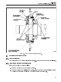
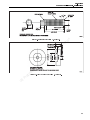
5.1.1. Rotor Locking for Shipment
The rotor must be locked in position prior to shipment to prevent damage to bearings and other components of
the motor. Figure 2 depicts the 5GEB22 rotor locking arrangement. To lock the rotor for shipment:
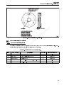
1. Remove two diametrically opposite bearing cap bolts and washers (Item 31, Figure 15 ). Place the removed
bearing cap bolts and washers into a bag that will be attached to the locking bolt.
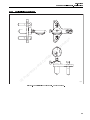
2. Thread 0.625–11 x 4.54 in. lock bolts (with jam nuts threaded onto the bolts) into the bearing cap holes as
shown in Figure 6 . The lock bolt heads are painted yellow to distinguish the bolts as rotor locking bolts.
3. Torque the rotor locking bolts to 30 lb.–ft. (40,7 Nm). To secure the locking bolts into place, run the jam nuts
down to the bearing cap and tighten.
4. Secure the bag containing the two removed bearing cap bolts and washers to the rotor locking bolts as
shown in Figure 2 .
5.
n
o
i
After motor shipment, the rotor locking bolts must be removed prior to the motor
at going into service. To
remove the rotor locking bolts:
m
r
a. Back the jam nuts away from the bearing cap.
fo
n
I
l
b. Remove the bearing cap bolts from the attached bag
on
ia the rotor locking bolts.
t
n bearing cap holes.
c. Thread the bearing cap bolts and washers intoethe
id
f
nlb.–ft. (156 ±20,3 Nm).
d. Torque the bearing cap bolts to 115 ±15
o
C
e. Place the removed rotor locking
bolts and jam nuts into the bag and store for future motor shipd
n
ment.
a
y
r
a
t
e
ri
p
ro
P
GE
Figure 6. Rotor Lock Bolts.
17
GEK-91696D
1150 HP AC Drilling Motor, Model 5GEB22
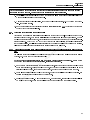
5.1.2. Motor Packaging for Shipment
After locking the rotor for shipment, the motor should be securely packaged to avoid damage during shipment.
To package the motor for shipment:
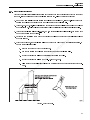
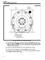
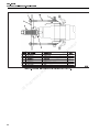
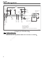
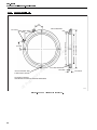
1. Prepare wood stock of sufficient length to skid the motor as shown in Figure 7 . The yellow pine wood stock
must be able to support the approximate 5700 lbs. (2585 kg) weight of the motor (not including the blower
and connection box).
2. Drill 1.62 in. (41,2 mm) clearance holes in the wood stock to fit the holes in the motor mounting feet (four
holes).
WARNING: The drill motor weighs approximately 5689 lbs. (2580 kg). Use appropriate lifting devices when lifting
the motor. Failure to do so may result in injury or death.
3. To avoid damage to the motor during handling:
a. Do not lift the motor by the rotor shaft.
a
rm
fo
n
I
c. Do not wrap the rotor with straps or banding for shipment.l Any securing straps or banding should
ia
be wrapped around the motor frame.
t
nholes with the wood frame holes.
e
4. Lift the motor onto the wood frame and align the motordfoot
fi mounting feet and wood stock frame. Tighten the
n
5. Install four 1.5–6 in. bolts and washers through the
motor
o
bolt into position.
C
d
6. Slush the machined surfaces with a rustninhibitor before enclosing the motor for shipment.
a
y
Motor Storage
r
a
t
for storage to prevent damage.
The motor should be preparedie
r
p
1. When preparing the
romotor for storage:
P
a. Construct
to secure the motor as described in section 5.1.2. Motor Packaging for ShipGEin thisa platform
ment
publication.
b. Do not allow the motor to impact another object when lifted.
5.1.3.
it on
b. Slush the exposed machined surfaces with a rust inhibitor.
c. Install wire leads to the anti−condensation heater that allow the heater leads to be connected to
an external power source.
d. Install cover and side panel to crate the motor.
e. Apply power to the anti−condensation heater while motor is stored.
18
GEK-91696D
1150 HP AC Drilling Motor, Model 5GEB22
ALLOW CONTAINER
CLEARANCE FROM
MOTOR ON BOTH ENDS
a
rm
fo
n
lI
1.5-6 BOLTS, NUTS, AND
WASHERS, 4 PLACES
it on
ia
t
en
Co
id
f
n
APPROXIMATE WEIGHT OF MOTOR 5689 LBS (2580 KG)
d
n
a
When removing the motor from storage:
y
r
a
a. Disconnect powert from the anti−condensation heater.
ie
r
b. Remove the
opcrating material from the motor.
r
P the rust inhibitor from the machined surfaces.
c. Remove
E
G
E-50540
Figure 7. Shipment Preparation for the 5GEB22 Motor.
2.
d. Visually inspect the motor for excessive rust or other defects.
e. Megger the stator leads as described in section 4.1.3. Megohmmeter Test in this publication.
f. If the motor has been in extended storage, the grease in the bearing should be replaced. Follow the
overhaul instructions in the following sections to disassemble the motor for bearing access.
5.2.
DISASSEMBLY PROCEDURES
5.2.1. Hub Removal
When removing a hub, use a suitable puller, similar to Part 41B535703G1, Figure 32 . This is a simple, efficient
hydraulic puller employing the float method of removal. A complete unit consists of a pump kit, a backing plate,
an adapter, a felt ring and a bolt.
19
GEK-91696D
1150 HP AC Drilling Motor, Model 5GEB22
NOTE: Do not heat the hub before pulling it, and do not use steel wedges between the hub and bearing cap.
1. Remove the set−screw plug from the tapped hole in the end of the shaft.
2. Screw the backing plate, with felt ring in place, to the end of the shaft as tight as possible by hand. Back off
the backing plate to line up the slot with the tapped hole in the end of the shaft. This is to provide sufficient
clearance for the hub to pop off.
3. Screw the pressure−fitting adapter into the hole in the shaft until it seats at the bottom.
4. Attach the pump by screwing the connector on one end of the pressure tube into the adapter, and the other
end into the pump.
5. Close the hand relief valve and work the pump handle to force oil into the groove in the armature shaft under
the hub. When sufficient pressure has been built up, the hub will pop off the shaft and be stopped by the
felt washer and backing plate.
n
o
i
NOTE: Capacity of the pump is 40,000 psi (275800 kPa). It holds sufficient oil to remove
eight to ten hubs;
at oil.
check at each use. Periodically, remove the filling plug and refill with SAE−10 lubricating
m
r
6. Open the relief valve, disconnect the pump from adapter, remove the adapter
fo and backing plate from the
n
shaft, and lift off the hub. Reinsert the plug to prevent clogging the hole.
I
l
ia
5.2.2. Rotor Removal
t
n
e
To remove the rotor from the motor assembly:
id
f
n to the rotor, bearings, or bearing fits when
CAUTION: Special precautions should be taken to avoid o
damage
lifting the rotor in the vertical position or turning the rotor
C to a horizontal position.
d
n numbers in Figure 15 located in section 6.2. DRILL MOTOR
NOTE: Numbers in parenthesis () refer toaitem
COMPONENT IDENTIFICATION of thisrpublication,
unless otherwise noted.
y
aposition.
t
1. Place the motor in a horizontal
e
ri
2. Remove the eight boltspand flat washers (31) securing the connection−end bearing housing to the connecro Remove the connection−end bearing cap
tion−end frame head.
P
E guide studs (.625–11 X 10) through the frame head and into the connection−end bearing
3. Screw twoGlong
inner cap (35) in opposite holes of the six just emptied. These studs will help to guide the rotor out of the
motor frame.
4. Place the motor on a heavy−duty stand with the drive−end up. Level the motor so that the rotor can be lifted
vertically with a hoist without damaging the bearing or bus rings.
5. Remove the eight bolts (10) and flat washers holding the drive−end frame head to the motor frame.
6. Screw a 1 in.−8 steel lifting eyebolt into the threaded hole in the drive−end of the rotor shaft (5).
7. Align the hoist cable with the center line of the rotor and attach the hoist hook to the lifting eye.
NOTE: The connection−end bearing and housing and the drive−end frame head, bearing and housing are
removed with the rotor as an assembly.
20
GEK-91696D
1150 HP AC Drilling Motor, Model 5GEB22
CAUTION: Use extreme care when turning the rotor to the horizontal position to avoid damage to the core and
the bearing and frame head fits. Use two hoists when positioning the rotor horizontally.
8. Carefully lift the rotor assembly out of the motor stator and place the rotor in a horizontal position on a
wooden cradle supporting the core assembly.
9. With the rotor in the horizontal position, remove the two long guide studs (.625–11 X 10) from the connection−end bearing housing.
10. Remove and service the rotor bearings according to instruction in section 5.2.3. Connection End (CE) Bearing
Assembly Removal of this publication.
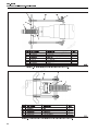
5.2.3. Connection End (CE) Bearing Assembly Removal
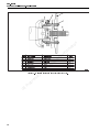
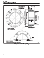
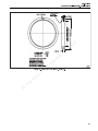
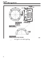
There are two Connection End (CE) bearing assemblies used for the 5GEB22 models. Models of the 5GEB22 manufactured prior to October, 2001 use the original design CE bearing assembly as shown in Figure 8 . 5GEB22
models manufactured after September, 2001 ( Figure 9 ) use an enhanced performance CE bearing assembly.
Refer to section 6.2. DRILL MOTOR COMPONENT IDENTIFICATION in this publication for details of differences in
the CE bearing designs. The following sections describe the CE bearing removal for both designs of CE bearings.
Select the removal procedure appropriate for the bearing design on the drill motor.
a
rm
fo
n
lI
it on
5.2.3.1. Connection End Bearing Assembly Removal Procedure for 5GEB22 Models Manufactured Prior to October,
2001
ia
t
en
The following procedure details the removal procedure for 5GEB22 drill motor models manufactured prior to
October, 2001. To remove the CE bearing assembly:
id
f
n in Figure 15 located in section 6.2. DRILL MOTOR
NOTE: Numbers in parenthesis () refer to item numbers
o
COMPONENT IDENTIFICATION of this publication,
unless otherwise noted.
C
drotor bearing nut (33). Attach the spanner wrench (GE Tool 9945228)
1. Remove the two set screws (40) from the
n
a blow hammer, tap the wrench handle in a counter clockwise (CCW)
to the rotor bearing nut. Usingya dead
r the spanner wrench, and remove the bearing nut from the rotor.
direction to loosen the nut. Remove
a
2. Assemble the bearingrpuller
iet (GE Tool 41D736059G3), and use the hydraulic jack to pull the connection–end
bearing housing (35)
opand bearing (34) from the rotor shaft.
r
P housing – with the bearing down – on a flat surface. Reassemble the bearing puller (to
3. Position the bearing
E
GE Tool 41D736059G4), and use the hydraulic jack to push the bearing from the bearing housing.
G
21
GEK-91696D
1150 HP AC Drilling Motor, Model 5GEB22
±
±
±
±
a
rm
fo
n
lI
it on
ia
t
en
id
f
n
o
C
d
r
a
t
n
a
y
Figure 8. Connection End (CE) Bearing Assembly for Models Manufactured Prior to September 2001.
ie
r
op
r
P
GE
22
GEK-91696D
1150 HP AC Drilling Motor, Model 5GEB22
±
it on
a
rm
fo
n
lI
±
±
±
ia
t
en
id
f
n
o
C
d
n
a
y
r
a
t
Figure 9. Connection End (CE) Bearing Assembly for Models Manufactured After September 2001.
ie
r
op
5.2.3.2. Connection End Bearing Assembly Removal Procedure for 5GEB22 Models Manufactured After September,
2001
r
P
GE
The following procedure details the removal procedure for 5GEB22 drill motor models manufactured after to
September, 2001. To remove the CE bearing assembly:
NOTE: Numbers in parenthesis () refer to item numbers in Figure 15 located in section 6.2. DRILL MOTOR
COMPONENT IDENTIFICATION of this publication, unless otherwise noted.
1. Remove the four bearing clamp (41) retaining bolts and hardened washers (42).
2. Thread two bolts into the bearing clamp (41) jack out holes. Tighten the bolts alternately until the bearing
clamp (41) is free of the rotor shaft fit. Remove the bearing clamp and remove the jack out bolts from the
bearing clamp.
3. Assemble the bearing puller (GE Tool 41D736059G3), and use the hydraulic jack to pull the connection–end
bearing housing (35) and bearing (34) from the rotor shaft.
4. Position the bearing housing – with the bearing down – on a flat surface. Reassemble the bearing puller (to
GE Tool 41D736059G4), and use the hydraulic jack to push the bearing from the bearing housing.
23
GEK-91696D
1150 HP AC Drilling Motor, Model 5GEB22
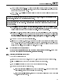
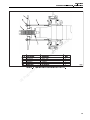
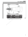
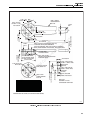
5.2.4. Drive End Bearing Assembly Removal
The following procedures details the drive end (DE) bearing assembly ( Figure 10 ) removal. To remove the DE
bearing assembly:
NOTE: Numbers in parenthesis () refer to item numbers in Figure 15 located in section 6.2. DRILL MOTOR
COMPONENT IDENTIFICATION of this publication, unless otherwise noted.
1. Remove the eight bolts and the flat washers (8) from the outer bearing cap (7).
2. Support the weight of the DE frame head (11) with a hoist, taking care not to lift the rotor off its support.
Assemble the bearing puller and use the hydraulic jack to pull the frame head (11), roller bearing (3), and
inner bearing cap (12) from the rotor.
3. Use an arbor press and fixtures to separate the bearing assembly (3) from the DE frame head (11).
it on
4. Remove the inner shaft collar (1) only if damaged, if outside of inspection limits, or if the shaft must be removed from the rotor. If necessary, use a puller to remove the sleeve.
a
rm
5.2.5. Connection End Frame Head Removal
fo
n
lI
Removal of the connection end frame head may be required to gain access to the bus rings and stator coil
connections. To remove the CE frame head:
ia
t
en
NOTE: Numbers in parenthesis () refer to item numbers in Figure 15 located in section 6.2. DRILL MOTOR
COMPONENT IDENTIFICATION of this publication, unless otherwise noted.
id
f
nthe frame head (27) to the stator frame (21).
1. Remove the eight bolts and flat washers (28) holding
o
C holes of the CE frame head (27). Evenly tighten the jack
2. Thread three 1–8x3 jack out bolts into the threaded
d
out bolts until the frame head is free of the
n stator frame (21) fit.
a
y 220 lbs. (100 kg). Use appropriate lifting devices for this
r
WARNING: The CE frame head weighs approximately
a or death.
t
weith. Failure to do so may result in injury
e
ri
3. Lift the frame head (27)pfrom the stator frame (21).
ro
P
GE
24
GEK-91696D
1150 HP AC Drilling Motor, Model 5GEB22
±
±
a
rm
fo
n
lI
it on
ia
t
en
id
f
n
o
C
d
n
a
y
r
a
t
ie
r
op
5.3.
r Figure 10. 5GEB22 Drive End (DE) Bearing Assembly.
P
E REPAIR PROCEDURES
GAND
INSPECTION
5.3.1. Rotor Shaft Inspection
Check dimensions as shown in Figure 16 located in section 6.3.1. Rotor Shaft Inspection Data in this publication.
5.3.2. Stator Coils and Bus Rings Connection Inspection
Inspect the stator coils and bus rings as follows:
1. Examine the bus rings for damaged or loose connections.
2. Observe the condition of the coil insulation and varnish. Evidence of burned or charred insulation or varnish
may indicate an overheating condition from a defective connection or defective coils.
25
GEK-91696D
1150 HP AC Drilling Motor, Model 5GEB22
5.3.2.1. Repairing Stator Coils to Bus Ring Connection, Cleaning and Breaking the Connection
The connection of the stator coils to the bus ring can be repaired when the connection shows signs of overheating. The connections are exposed by cutting and stripping the insulation around the connection requiring the
use of a hammer, knife, chisel, screwdriver, pry bar, and slip joint pliers. To expose the connections for repair:
NOTE: Read this entire procedure first to become familiar with these steps.
1. Position the stator frame to obtain the best working position for the connections to be cleaned.
2. Remove any mounting hardware (bolts, nuts, insulating blocks, etc.) from the area of the brazed connection.
3. Use the knife, chisel, and hammer to cut the insulation. Cut the insulation down to the copper the full length
of the connection.
it on
4. After cutting the insulation the full length, pry the insulation away from the connection using the slip joint
pliers, pry bar, screwdriver, or knife.
a
5. Brazing tool heat can be used to soften the insulation for final cleaning. Alternately heat the insulation, and
scrape off all material until reaching bare copper.
rm
fo
n
lI
NOTE: Use the resistance brazing machine (GE Tool 41D780746–1 or equivalent) and tongs (GE Tool
41D780746–11 or equivalent) to produce the heat necessary to separate the connection. Passing current
through the brazing tongs carbons and the metal to be separated produces heat.
ia
t
nfree of dirt, oil and insulating material such as
e
6. The area of the joint to be disconnected must be clean d
and
varnish and tape.
fi
n
o when using compressed air. Failure to do so
WARNING: Observe all government and shop safety regulations
C
d
may result in injury.
n
a that is to be opened. Keep an air supply nozzle on hand to cool
7. Position the brazing tong on the connection
y
parts after separation occurs. a
Ther air supply also is used to cool the surrounding area by dissipating heat
from the area being heated.
ir et
pin pulses ONLY. This enables the heat to spread out gradually, providing a more
CAUTION: Power is to be applied
o
r
even heating of the connection
P area, and eliminating any intense hot spots that may damage the ring or coil
material.
E
G
8. Apply power to the brazing tongs in pulses ONLY until the heat melts the brazing material in the joint, then
shut off the power.
9. Quickly remove the brazing tongs, and using the screwdriver or pry bar, spread the connection joints before
the solder cools and resolidifies.
10. When the bus ring and stator coil connections are separated, repair or replace damaged bus rings, straps,
or stator coil leads prior to brazing the connection together.
11. Before brazing together, ensure the material is clean, parts being brazed are flat against each other to prevent voids.
5.3.2.2. Repairing Stator Coils to Bus Ring Connection, Brazing and Insulating
To braze and insulate the connection after repairs have been made:
26
GEK-91696D
1150 HP AC Drilling Motor, Model 5GEB22
NOTE: The brazing median can be used in strip form (GE Part 41A231281P46) or rod form (GE Part
41A330300P2). It is recommended that strips 0.010 in (0.25 mm) thick cut into squares or rectangles 0.06 in.
(1.6 mm) larger than the conductors, be used for the initial connection. Use the brazing rod to fill voids after
the initial connection. Use of this material eliminates the need for flux.
1. The connection area of the material to be brazed must be clean and free of dirt, oil, and insulating materials.
2. If necessary, bend the soft copper connecting straps to align the connection.
NOTE: When using brazing material in strip form, the strip should be sandwiched between the two pieces
being brazed, which must be flat along the entire length of the joint.
3. Insert a brazing strip between the two connecting straps being brazed.
4. Position the brazing tongs on the area to be brazed, and clamp in place.
it on
WARNING: Observe all government and shop safety regulations when using compressed air. Failure to do so
may result in injury.
a
m
CAUTION: Power is to be applied in pulses ONLY. This enables the heat to spreado
outr gradually, providing a more
f
even heating of the connection area, and eliminating any intense hot spotsnthat may damage the ring or coil
I
material.
l
iathe brazing solder flows freely. Using an air
t
5. Apply power to the brazing tongs in pulses ONLY, and heat
until
n
nozzle, blow air on the surrounding area while heatingeto dissipate heat from the area being brazed.
id
f
NOTE: When brazing, silver solder in rod form will n
be required to fill areas where the strip may have dripped
o
out or to fill voids.
C
d
6. Remove power from the tongs, but do
the tongs until the silver solder has cooled enough to
n NOTairrelease
a
hold the connection. Blowing compressed
on the brazed area will speed the cooling.
y
r
ausing Micamat (part number 41A239176P215) and half lap insulating tape (part
7. Insulate the connection area
t
e
number 41A239176P15)
or
i other appropriate insulation material specific to the connection area.
r
8. Varnish application
opover the new insulation is required either by P5D-EP25 VPI process or hand application.
r
P
5.3.3. Stator / RotorEReconditioning
G
The stator and rotor must be reconditioned during the overhaul procedures before being returned to service.
These process help ensure long operating life for the components.
The stator assembly should be treated by Vacuum Pressure Impregnation (VPI) with an approved varnish. VPI
will seal and secure the stator coils. VPI only after cleaning, inspection and testing of the stator assembly. The
VPI process is GE Process P5D–EP25.
The rotor assembly should be treated by a powder coating process. Powder coat the rotor after cleaning and
inspecting. The powder coat treating is GE Process P6C–EP45.
Due to changing technology, contact your local GE representative or Drill Product Service Center for current
instruction processes at time of overhaul. Drill product Service Center contact information as follows:
27
GEK-91696D
1150 HP AC Drilling Motor, Model 5GEB22
GE Transportation
Attention Drill Product Service
2901 East Lake Road
Erie, PA 16531
www.GEtransportation.com
5.4.
STEAM CLEANING
5.4.1. Steam Cleaning Introduction
WARNING: Cleaning agents may be toxic and/or flammable. Cleaning agents can cause serous or fatal injury
if used without proper precautions. For safety; do not inhale fumes, use only in adequately ventilated areas,
avoid contact of cleaning agents with the skin, do not expose cleaning agent to flame or sparks, and observe
cautions and warnings issued by the manufacture of the cleaning agent.
it on
a
m
Care must be taken in the selection and strength of cleaning agents or detergents rused in conjunction with steam
oneutral. Check the pH level with
cleaning. Typical cleaning agents pH (alkalinity) are alkaline and not chemically
facceptable
n
range. If pH test paper
a pH monitor or pH test paper strips to ensure of the cleaning solution is inIan
l
is used, Table 6 depicts the pH test paper color and corresponding alkalinity
ia level.
t
n
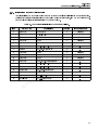
TABLE 6. CLEANING AGENT PH DATA.
e
id Base−Alkaline
f
Acid
Neutral
n
o
5—6
7
8
10
11
C 9
d
Orange
Yellow
Greenn
Ivy—Green
Blue
Purple
a
y greasy mechanical equipment is cleaned should not be used to clean
Cleaning processes in which heavy, dirty,
r
a make up and high concentrations of cleaning agents in solution, utilizing
electrical equipment. Due to chemical
t
e
the mechanical equipment cleaning
ri processes on electrical equipment can have a significant impact on the life
of the electrical insulation p
systems used in motors
o
r
P
A suggested cleaning agent for use in steam cleaning processes for electrical equipment is CM−809−S (or equivE agent is available at Chem Methods, Inc., 12703 Trisket Road, Cleveland, OH 44111. Chem
alent). This cleaning
G
Methods, Inc. telephone number is (216) 476−8400. This cleaning agent is Potassium Phosphate based and does
not contain caustic materials or silicate.
The mixed steam cleaning solution should be heated to 158 °F to 194 °F (70 °C to 90 °C) and have a pH of 10.5
to 11.0. Approximately a 10% solution of the cleaning agent and heated water should achieve the pH level. The
10% solution should be used on the rotor and stator of the motor. If needed, a 50% solution of the cleaning
agent and heated water can be used on the motor frame externally. Do not allow the stronger solution to leak
internally to the motor.
To control the cleaning agent in solution, a steam cleaner with an adjustable soap (cleaning agent) valve should
be used.
28
GEK-91696D
1150 HP AC Drilling Motor, Model 5GEB22
To clean the motor:
1. Using the 50% solution, spray the external motor frame with the cleaning solution. Let the cleaning solution
soak the motor frame five to twenty minutes (depending on the contaminant) to penetrate the accumulated
contaminants.
2. If deposits of contaminants are too heavy to be steam cleaned off, manually scrap the debris off and steam
clean.
3. Rinse the cleaning solution off motor with steam and hot water.
4. Blow the motor frame dry with clean, dry compressed air.
5. After motor disassembly during the overhaul process, clean the internal motor components using a 10%
cleaning solution.
it on
6. Rinse of the cleaning solution off with hot water heated to a minimum 194ºF (90ºC).
a
rm
NOTE: The internal motor components must be thoroughly rinsed. Cleaning solutions may form a crystalline
compound if left on the motor components. The motor insulation systems may be affected by the crystalline
deposits which may shorten the insulation life.
fo
n
lI
ia
t
en
WARNING: When using compressed air, loosened debris may make the surrounding area dangerous for personnel. Ensure all personnel are clear and wear appropriate safety equipment. Follow all local regulations and
procedures for compressed air use. Failure to do may result in injury or death.
id
f
n
o
C
d
7. Using clean, dry compressed air, blow excess water off internal motor components.
8. Bake the motor electrical parts in a ventilated oven at 257ºF to 320ºF (125ºC to 160ºC) for 8 to 12 hours.
n
a
y
9. Allow parts to cool to room temperature and visually inspect for defects.
r
a
t
10. Perform the Megohmmeter and High−Potential tests described in section 5.5.1. Static Electrical Testing Introduction of this publication.
5.5.
ie
r
p does not meet specifications in tests, bake an additional two hours in the oven and
11. If the stator assembly
o
r
retest.
P
E
STATIC ELECTRICAL
G TESTING
5.5.1. Static Electrical Testing Introduction
Static electrical tests include a Megohmmeter test and High−Potential (Hi−Pot) test. Both tests check motor insulation systems. Always perform the Megohmmeter test prior to the Hi−Pot test. High voltage used in the Hi−Pot
test may be destructive to insulation if water or debris is present. If the Megohmmeter test indicates moisture or
debris is present, clean the stator as described in section 5.4.1. Steam Cleaning Introduction of this publication.
Once the Megohmmeter test specification is met, proceed to the Hi−Pot test.
5.5.1.1. Megohmmeter Test
Perform the Megohmmeter test as described in section 4.1.3. Megohmmeter Test in this publication.
29
GEK-91696D
1150 HP AC Drilling Motor, Model 5GEB22
5.5.1.2. High–Potential (Hi–Pot) Test
WARNING: High−Potential (Hi−Pot) testing is performed with high voltage electrical power. Follow safety regulations and local practices for high voltage testing. Failure to do so may result in injury or death.
Hi−Pot tests evaluate the insulation dielectric strength (ability to insulate) of the motor insulation systems. High
voltage is applied to each motor phase to test insulation to ground during the test. To perform the Hi−Pot test:
CAUTION: Always perform the Megohmmeter test before Hi−Pot test. Damage may occur to insulation during
Hi−Pot testing if moisture or debris is present in the coils of the stator. Failure to do so may result in permanent
damage to the stator windings requiring replacement of the stator.
1. Ground one lead of the RTD temperature sensor for sensor protection. Do not Hi−Pot the RTD during testing.
it on
2. Apply the specified high voltage at 60 Hz to each motor lead for one minute with the other lead of the Hi−Pot
connected to ground. There should not be any significant current (amperage) leakage to ground during
testing. The voltage applied should be:
fo
n
lI
a. New or recoiled stator − apply 3500 VAC rms.
b. Reconditioned stator − apply 2500 VAC rms.
c. In−service or used stator − apply 2250 VAC rms.
a
rm
ia
t
en
id
f
n
3. If the stator windings show significant current leakage to ground, clean the stator as described in section
5.4.1. Steam Cleaning Introduction in this publication. After cleaning, retest the stator windings.
5.6.
ROTOR SUBASSEMBLY PROCEDURES
5.6.1. Rotor Balancing
o
C
d
n
a
y
r
a
t
Dynamic balance of the rotor assembly is required for smooth operation and low vibration. If not corrected, an
out−of−balance rotor will lead to complete motor failure.
ie
r
The rotor must be balanced
opto within 50 gram−in. at both ends of the rotor.
r
P only to the location and method of attaching the balance weights. The set−up, fixtures
These instructions pertain
E
to hold components
G in the balance machine, and the procedures required to obtain a balance within specified
limits is dependent on the type of balance machine. Therefore, follow the operating procedures for the balance
machine used.
CAUTION: Use ONLY the specified welding rod. Use of other types may result in poor welds leading to motor
failure.
NOTE: Keep weld splatter out of the rotor core vent holes when welding balance weights to the end plate.
Attach the balance weights as needed by welding to the rotor end plates at a diameter of 13.75 in. (276,9 mm).
Use welding rod GE Spec. G50E37, BRONZE (AWS−E−Cu−Sn−C). Weld the balance weights using GE weld process
P8B−EP35.
30
GEK-91696D
1150 HP AC Drilling Motor, Model 5GEB22
5.6.2. Connection–End (CE) Frame Head Installation
NOTE: Numbers in parenthesis () refer to item numbers in Figure 15 located in section 6.2. DRILL MOTOR
COMPONENT IDENTIFICATION of this publication, unless otherwise noted.
WARNING: The CE frame head weighs approximately 220 lbs. (100 kg). Use appropriate lifting devices for this
weith. Failure to do so may result in injury or death.
To assemble the connection–end frame head (27), align the frame head on the motor frame. Install and
hand–tighten the eight bolts and hardened flat washers (28) holding the frame head (27) to the motor frame
(21). Then torque the bolts evenly in a diametrically opposite sequence to 468 ±28 lb–ft (634 ±38 Nm).
5.6.3. Connection−End (CE) Bearing Assembly
To assemble the CE bearing onto the 5GEB22 rotor:
it on
NOTE: Numbers in parenthesis () refer to item numbers in Figure 15 located in section 6.2. DRILL MOTOR
COMPONENT IDENTIFICATION of this publication, unless otherwise noted.
a
m
r area dangerous for perWARNING: When using compressed air, loosened debris may make the surrounding
o
f
sonnel. Ensure all personnel are clear and wear appropriate safety equipment.
In Follow all local regulations and
procedures for compressed air use. Failure to do may result in injury orldeath.
ia
t
1. Using clean, dry, compressed air, blow debris from CE bearing
n mounting area on the rotor shaft (5).
e
id parts are clean and free of damage or burrs.
2. Inspect all CE bearing assembly components to ensure
f
n
o
3. The rotor assembly must be in the horizontal
position
and blocked to prevent rotation or movement during
C
the assembly procedure.
d
n
4. If removed, install the rotor lockingacollar (36). To install the collar:
y
r
a collar (36) to 212°F (100°C) in an oven.
a. Heat the rotor locking
t
e
ri
WARNING: Components heatpin ovens may be hot enough to cause injury. Use appropriate safety equipment
rofor handling heated components. Failure to do so may result in injury.
and follow shop procedures
P
E
b. GRemove the locking collar (36) from the oven and place onto the rotor shaft. Press the collar into
position against the shoulder of the rotor shaft (5).
c. Secure the collar into position until it cools.
5. Fill the cavity of the CE inner bearing cap (35) with 2.2 oz. (62.4 g) of GE specification D6A2C10 grease.
6. Pack the CE bearing (34) with 5 oz. (142 g) of GE specification D6A2C10 grease.
7. Evenly heat the CE inner bearing cap (35) to 212°F (100°C) in an oven to expand the cap’s bearing fit for the
CE bearing (34). Remove the inner bearing cap (35) from the oven and place onto a flat surface. Press the
CE bearing (34) (rotor side of the bearing as shown in Figure 15 ) into the inner bearing cap (35) bearing fit.
8. Cover or coat the CE rotor shaft (5) running surfaces with 0.25 oz. (7 g) of GE specification D6A2C10 grease.
31
GEK-91696D
1150 HP AC Drilling Motor, Model 5GEB22
9. Heat the CE inner bearing cap, with the CE bearing, to 212°F (100°C) in an oven. Remove the heated assembly
from the oven and immediately slide the assembly onto the CE end of the rotor shaft. Press the assembly
tightly against the shaft shoulder. Secure the assembly in position until cool.
10. Securing the CE bearing assembly on the rotor shaft (5) depends on the 5GEB22 model. Select the appropriate process for the 5GEB22 model.
a. For 5GEB22 models manufactured prior to September, 2001, the CE bearing assembly is secured
on the rotor shaft with a bearing retaining nut (33). Refer to Figure 8 for grease application during
assembly process. To secure the bearing assembly on the rotor shaft, thread the nut into the tapped
end of the rotor shaft until hand tight. Insert a spanner wrench (tool number 9945228) into the
holes on the outside flat of the bearing nut. Using a brass sledgehammer, strike two or three sharp
blows, driving the nut clockwise, approximately one quarter turn from hand tightened. Thread the
two locking set screws (40) into the bearing retaining nut (33) and torque the set screws to 40 ±2
lb—ft (54 ±3 Nm). Using a heavy center punch, stake or peen each set screw in two places to prevent
loosing.
it on
a
rm
b. For 5GEB22 models manufactured after September, 2001, the CE bearing assembly is secured on
the rotor shaft with a bearing clamp (41). Refer to Figure 9 for grease applications during assembly
process. To secure the bearing assembly on the rotor shaft, Inspect the rotor shaft bore (5) and
clamp (41) to ensure the components are free of damage and burrs. Lightly coat the rotor shaft
bore with GE specification D6A2C10 grease to facilitate assembly. Insert the bearing clamp into the
rotor shaft bore. Thread the clamp bolts (42) through the clamp into the tapped holes of the rotor
shaft. Tighten the clamp bolts alternately to evenly to draw the clamp into the rotor shaft bore.
When the clamp is fully seated in the rotor shaft, torque the clamp bolts to 58 ±2 lb—ft (78 ±3 Nm).
fo
n
lI
ia
t
en
id
f
n
o
C
d
11. Apply the gasket and assemble the dummy CE bearing cap 41C689896 ( Figure 36 ) with four bearing cap
bolts and hardened washers (31). Thread the bolts through the dummy bearing cap into the inner bearing
cap (35) to secure the bearing assembly.
n
a
y
r
a
t
5.6.4. Drive End (DE) Bearing Assembly
ie
r
op
NOTE: Numbers in parenthesis () refer to item numbers in Figure 15 located in section 6.2. DRILL MOTOR
COMPONENT IDENTIFICATION of this publication, unless otherwise noted.
r
P
GEcompressed air, loosened debris may make the surrounding area dangerous for perWARNING: When using
To assemble the DE bearing:
sonnel. Ensure all personnel are clear and wear appropriate safety equipment. Follow all local regulations and
procedures for compressed air use. Failure to do may result in injury or death.
1. Using clean, dry compressed air, blow any loose debris clear of the DE rotor shaft (5).
2. Inspect the DE bearing assembly and rotor shaft to ensure parts are free of damage and burrs.
3. The rotor should be in the horizontal position and blocked to prevent movement and rotation.
WARNING: Components heated in ovens may be hot enough to cause injury. Use appropriate safety equipment
and follow shop procedures for handling heated components. Failure to do so may result in injury.
4. If removed, install the inboard DE shaft collar (1) onto the rotor shaft (5). to install the rotor shaft:
32
GEK-91696D
1150 HP AC Drilling Motor, Model 5GEB22
a. Heat the shaft collar (1) to 212°F (100°C) in an oven.
b. With the rotor in a horizontal position, remove the collar from the oven and press onto the rotor
shaft (5) drive end until seated against the rotor shaft shoulder. Secure the collar in place until cool.
c. After the collar has cooled, coat the rotor shaft collar’s running surfaces with GE specification
D6A2C10 grease as shown in Figure 10 .
d. Pack approximately 8 oz. (227 g) with GE specification D6A2C10 grease into the DE inner bearing
cap (12) as shown in Figure 10 . Coat the inner bearing cap running surfaces with the same grease.
5. Place the inner bearing cap in position over the DE shaft collar (1).
6. Install the flinger (2) onto the rotor shaft drive end. To install the flinger:
n
o
i
t
b. Ensure the inner bearing cap (12) is in position on the rotor shaft driveaend.
rmoven and press onto the rotor
c. With the rotor in a horizontal position, remove the flinger fromothe
f (1). Secure the flinger in position
shaft drive end until the flinger is seated against the shaftncollar
I
until cool.
l
a
i
t specification D6A2C10 grease.
d. When the flinger has cooled, coat the flinger withnGE
ide(5) drive end. To install the bearing inner race:
Install the DE bearing (3) inner race onto the rotor fshaft
n
o
a. Heat the inner race to 212°F (100°C)
in
an oven.
C
d remove the inner race from the oven and press onto the rotor
n
b. With the rotor in a horizontal
position,
a
shaft drive end until theyinner race is seated against the flinger (2). Secure the inner race in position
r
until cool.
a
t
e
i
r race has cooled, coat the race with GE specification D6A2C10 grease.
c. When the inner
p
ro(rollers and outer race) with 16 oz. (454 g) with GE specification D6A2C10 grease as shown
Fill the DE bearing
P
in Figure E
10 .
G
a. Heat the flinger to 212°F (100°C) in an oven.
7.
8.
9. Assemble the DE frame head (11), the DE inner bearing cap (12), and DE bearing (3) (outer race and rollers)
together. To assembly these components:
a. Cold press the DE bearing (3) (outer race and rollers) into the DE frame head (11). Refer to Figure 10
for approximate position of the bearing in the frame head.
b. Install the DE bearing pilot tool (8849499P7), Figure 37 , on the rotor shaft as shown in Figure 11 .
NOTE: Without the use of a rotor drive–end bearing pilot, the upper–most rollers will drop toward the center,
making the assembly of rollers over the inner race difficult. Refer section 6.4. SPECIAL TOOLS AND MATERIALS in this publication for the bearing pilot, guide stud and dummy bearing cap part numbers.
c. Thread a guide stud (.625–11 X 10) in the inner bear cap (12) as shown in Figure 11 .
33
GEK-91696D
1150 HP AC Drilling Motor, Model 5GEB22
d. Align the inner bearing cap gasket (9) over the guide stud onto the inner bearing cap (12) as shown
in Figure 10 .
WARNING: The DE frame head weighs approximately 75 lbs. (34 kg). use appropriate lifting devices for this
weight. Failure to do so may result in injury.
e. Lift the DE frame head (11) with a hoist, align on the guide stud, and install onto the rotor shaft over
the DE bearing as shown in Figure 12 . The DE frame head should remain supported by the hoist
until the inner bearing cap (12), the DE frame head (11), and the outer dummy bearing cap (7) are
bolted together.
f. Remove the DE bearing pilot tool (8849499P7) from the rotor shaft.
g. Install and align the outer gasket (9) over the guide stud onto the DE frame head.
it on
h. Align the dummy bear cap, Figure 38 , (6796493P3, used for assembly purposes) on the guide stud
and position against the DE frame head (11).
a
m
i. Thread four bearing cap bolts with washers (8) through the dummy bearing
and DE frame head
r the lastcapbearing
o
(11) into the inner bearing cap (12). Remove the guide stud and thread
cap bolt into
f
position. Tighten the bolts to secure the assembly together. In
it al until the rotor is installed in the
NOTE: Do not assemble the remaining DE bearing assembly components
n
stator frame.
e
id
f
n
o
C
d
n
a
y
r
a
t
e
ri
p
ro
P
GE
GUIDE STUD FOR
ASSEMBLING FRAMEHEAD
BOLTS IN INNER BEARING CAP
BEARING PILOT USED
TO GUIDE FRAMEHEAD
(WITH OUTER RACE AND
ROLLERS) OVER THE INNER RACE.
E-50559
Figure 11. DE Bearing pilot and Guide Studs Installed.
34
GEK-91696D
1150 HP AC Drilling Motor, Model 5GEB22
BEARING PLOT
GUIDE STUD
a
rm
fo
n
lI
it on
E-50560
ia
t
en
Figure 12. DE Frame Head Installed Over DE Bearing on Rotor Shaft.
5.7.
ROTOR INSTALLATION INTO THE STATOR FRAME
id
f
n
NOTE: Numbers in parenthesis () refer to item numbers in Figure 15 located in section 6.2. DRILL MOTOR
COMPONENT IDENTIFICATION of this publication, unless otherwise noted.
o
C
The rotor assembly is installed by lowering d
the rotor into the vertical stator frame. The rotor assembly consists
n
of the CE bearing with inner bearing capa(35), the rotor shaft (5) and core (23), the DE frame head (11), and the DE
bearing assembly (3) with the DE dummy
y bearing cap. To install the rotor assembly into the stator frame:
r
abe mounted on the stator frame (21) prior to rotor installation. If the CE frame
1. The CE frame head (27) must
t
e
i the CE frame head as follows:
head is not installed, rinstall
p
o stator frame (21) CE frame head fit is free of damage and burrs.
a. Ensurerthe
P
E
b. GEnsure the CE frame head (27) stator frame fit is free of damage and burrs.
c. Align the CE frame head (27) on the stator frame (21) so that the largest gap on the CE frame head
bearing cap mounting holes is toward the stator frame feet as shown in Figure 13 .
d. Thread the CE frame head eight mounting bolts and hardened flat washers (28) through the CE
frame head into the tapped holes of the stator frame (21).
e. Tighten the bolts to draw the CE frame head into the stator frame fit evenly.
f. When the CE frame head is fully seated against the stator frame, torque the mounting bolts to 468
±27 lb—ft (634 ±36 Nm).
35
GEK-91696D
1150 HP AC Drilling Motor, Model 5GEB22
a
rm
fo
n
lI
it on
ia
t
en
id
f
n
o
C
d
n
a
y
r
a
t
LARGEST BEARING CAP
BOLT SPACE TO BE AT
6 O’CLOCK POSITION
WHEN FRAME HEAD (27)
IS ASSEMBLED TO FRAME (21)
ie
r
op
r
P
GE Figure 13. CE Frame Head and CE Bearing Cap Alignment.
E-50831
2. Mount the stator frame in a heavy–duty stand with the Drive End (DE) up. Level the stator frame so that
the rotor can be lowered vertically into the frame with a hoist without damaging the bearings or bus rings.
Allow enough clearance for the guide studs on the rotor assembly to extend approximately 8 inches (203
mm) beyond the CE frame head (27)
3. Ensure the DE of the stator frame (21) is free of damage and burrs in the frame head fit.
4. Ensure the DE frame head (11), mounted on the rotor shaft, is free of damage and burrs.
5. Remove the CE outer dummy bearing cap from the end of the rotor shaft. The inboard CE gasket must
remain aligned on the inner bearing cap (35).
36
GEK-91696D
1150 HP AC Drilling Motor, Model 5GEB22
6. Thread two long guide studs (.625–11 X 10) into opposite holes of the inner bearing cap (35). Do not thread
the guide studs into the rotor locking ring (36). The studs must move freely to align with the CE frame head
(27) mounted on the stator frame (21).
7. Screw a 1 in.– 8 X 2.62 steel lifting eyebolt (GE Tool N672P39) into the threaded hole in the Drive End (DE) of
the rotor shaft.
WARNING: The partial rotor assembly weighs approximately 1887 lbs. (856 kg). Use appropriate lifting devices
for this weight. Failure to do so may result in injury or death.
CAUTION: Exercise extreme care when turning the rotor from the horizontal position to avoid damage to the
core and the bearing and frame head fits. A suitable turning fixture or two hoists should be used to position
the rotor vertically.
it on
8. Carefully lift the rotor assembly from the horizontal position, attaching a hoist hook to the lifting eye. Align
the hoist cable with the center line of the stator frame (21), and slowly lower the rotor into the motor frame,
guiding the long studs through the appropriate connection–end frame head (31) holes.
5.8.
5.8.1.
a
m
9. Install and hand–tighten the eight bolts and hardened flat washers (10) rholding the DE frame head (11) to
o fit then tighten the bolts evenly
the stator frame (21). If the DE frame head (11) does not seat into the fframe
n
in a diametrically opposite sequence until the DE frame head is mated
I to the stator frame. Following the
l
same diametrically opposite sequence, torque the bolts to the
value
ia of 472 ±24 lb—ft (640 ±32 Nm).
t
10. Rotate the motor to the rotor shaft horizontal position.en
id head using the two guide studs protruding through
f
11. Align the dummy bearing cap, Figure 36 , on the CE
frame
n
the CE frame head. Thread two bearing capobolts and hardened washers (31) into the open holes of the
dummy bearing cap. Remove the two guideCstuds and thread two bearing cap bolts and hardened washers
d to 115 ±5 lb—ft (155 ±7 Nm).
(31) into the open holes. Torque the bolts
n
MOTOR BEARING CHECKS AFTERrASSEMBLY
ya
a() refer to item numbers in Figure 15 located in section 6.2. DRILL MOTOR
t
NOTE: Numbers in parenthesis
e
ri of this publication, unless otherwise noted.
COMPONENT IDENTIFICATION
p
roBearing Runout Check
Connection End P
(CE)
To check the
GCEE bearing (34) runout:
1. Raise the CE end of the motor 4 to 6 in. (102 to 152 mm), and force the rotor toward the Drive End (DE).
2. Clamp a dial indicator on the face of the Connection End (CE) of the rotor shaft (5).
3. Zero the dial indicator reading on the face of the CE rotor bearing (34) outer race.
4. Rotate the rotor to determine the bearing runout.
a. If runout is within allowable limits for runout as shown in section 6.1.2. Drill Motor General Data in
this publication, proceed to the next bearing check procedure.
b. If runout is outside allowable limits, retighten the CE bearing cap bolts (31) and CE frame head bolts
(28). Repeat the runout check.
37
GEK-91696D
1150 HP AC Drilling Motor, Model 5GEB22
c. If runout remains excessive, disassemble the motor to check the CE frame head (27) bearing fit, and
the CE bearing housing (35) bearing fit, and inspect all parts for burrs, debris, or component wear
to determine cause of excessive bearing runout. Reassemble the motor and repeat runout check.
5.8.2. Drive End (DE) Bearing Runout Check
To check the DE bearing (3) runout:
1. Raise the DE end of the motor 4 to 6 in. (102 to 152 mm), and force the rotor toward the Connection End (CE).
2. Clamp a dial indicator on the face of the Drive End (DE) of the rotor shaft (5).
3. Zero the dial indicator reading on the face of the DE rotor bearing (3) outer race.
4. Rotate the rotor to determine the bearing runout.
it on
a. If runout is within allowable limits for runout as shown in section 6.1.2. Drill Motor General Data in
this publication, proceed to the next bearing check procedure.
a
rm
b. If runout is outside allowable limits, retighten the DE bearing cap bolts (8) and DE frame head bolts
(10). Repeat the runout check.
5.8.3.
fo
n
I DE frame head (11) bearing fit, and
c. If runout remains excessive, disassemble the motor to checkl the
a for burrs, debris, or component wear
the DE inner bearing cap (12) bearing fit, and inspect alltiparts
to determine cause of excessive bearing runout. Replace
any worn components. Reassemble the
n
e
motor and repeat runout check.
id
f
Drive End (DE) Bearing Radial Clearance Check on
C
To check the DE bearing (3) radial clearance: d
n4 to 6 in. (102 to 152 mm), force the rotor toward the Connection
a
1. With Drive End (DE) of the motor raised
y
End (CE).
r
a
t
e
equal
to the minimum radial clearance given in section 6.1.2. Drill Motor Gen2. Select a feeler gage thickness
i for the drive–end
r
eral Data of this publication
rotor bearing.
p
o
r flat against the rolling surface of the inner race of the DE rotor bearing (3), just in front
3. Place the feeler gage
P
of the uppermost
E bearing roller. Hand–turn the rotor shaft just enough to roll the top bearing roller over the
minimum G
radial clearance feeler gage.
4. Repeat the minimum clearance check for each bearing roller in the drive–end rotor bearing. Reject the bearing if one or more bearing rollers will not roll over the minimum radial clearance feeler gage.
5. Select a feeler gage thickness equal to the maximum radial clearance given in section 6.1.2. Drill Motor
General Data of this publication for the drive–end rotor bearing. Place the feeler gage flat against the rolling
surface of the inner race of the drive–end rotor bearing. Hand–turn the rotor shaft to check that none of
the bearing rollers will roll over the maximum radial clearance feeler gage. Reject the bearing if one or more
bearing rollers will roll over the maximum radial clearance feeler gage.
5.8.4. Rotor Shaft End–Play Check
To check rotor shaft (5) end—play:
1. With the motor horizontal, force the rotor to seat at the Drive End (DE).
38
GEK-91696D
1150 HP AC Drilling Motor, Model 5GEB22
2. Clamp a dial indicator to the motor frame at the Connection End (CE) of the motor or the dummy CE bearing cap. Zero the indicator ball on the face of the rotor bearing nut (33) for models manufactured prior to
September 2001 or the rotor bearing clamp (41) for models manufactured after September 2001.
3. Force the rotor back to seat at the Connection End (CE). The amount of rotor shaft end–play indicated must
not exceed the end–play given in section 6.1.2. Drill Motor General Data of this publication.
5.9.
FINAL ASSEMBLY OF ROTOR DRIVE END (DE) COMPONENTS
If the rotor bearings pass the bearing runout and radial clearance checks, install the remaining DE component
parts as follows:
NOTE: Numbers in parenthesis () refer to item numbers in Figure 15 located in section 6.2. DRILL MOTOR
COMPONENT IDENTIFICATION of this publication, unless otherwise noted.
n
o
i
2. Pack the DE outer bearing cap (7) with 8.0 oz. (227 g) of GE Specification D6A2C10tgrease. Ensure the gasket
a
(9) is in place between the bearing cap and frame head.
m
r
3. Assemble the bearing cap (7) insert to the DE frame head (11) and innerfo
bearing cap (12) with eight bolts and
hardened flat washers (8), and torque the bolts to 115 ±5 lb–ft (155In±7 Nm).
it athel sleeve:
4. Install the DE outer sleeve (4) onto the rotor shaft (5). To install
n
e
a. Heat the DE outer sleeve (4) to 110°C (230°F)
in
an
id oven.
f
n
b. Remove the sleeve from the oven andopress it onto the DE rotor shaft until seated against the inner
C
race of the DE bearing (3).
d
n
c. Secure the sleeve in placeauntil cool.
y
r
FINAL ASSEMBLY OF ROTOR CONNECTION
END (CE) COMPONENTS
a
t
ie parts as follows:
r
Install the remaining CE component
p
o
r
NOTE: Numbers P
in parenthesis () refer to item numbers in Figure 15 located in section 6.2. DRILL MOTOR
COMPONENTEIDENTIFICATION of this publication, unless otherwise noted.
G
1. Remove the dummy DE bearing cap.
5.10.
1. Remove the dummy CE bearing cap.
2. Apply 2.8 oz. (79.4 g) of GE Specification D6A2C10 grease to the CE bearing cap (32).
3. Align the CE bearing cap (32) with the largest gap between holes toward the mounting feet as shown in
Figure 13 . Assemble the bearing cap (32) to the CE frame head (27) and inner bearing housing (35) with
eight bolts and hardened flat washers (31), and torque the bolts to 115 ±5 lb–ft (155 ±7 Nm).
5.11.
ELECTRICAL RUNNING TESTS
After the motor has been reconditioned and reassembled, perform the following tests to ensure that the motor
will operate satisfactorily:
WARNING: Electrical tests are performed at high voltage. Electrical shock can cause serious or fatal injury.
Proper precautions should be taken and observed by personnel performing testing to avoid injury
39
GEK-91696D
1150 HP AC Drilling Motor, Model 5GEB22
NOTE: Numbers in parenthesis () refer to item numbers in Figure 15 located in section 6.2. DRILL MOTOR
COMPONENT IDENTIFICATION of this publication, unless otherwise noted.
1. Using stiff putty, secure thermometers to the Drive End (DE) (7) and Connection End (CE) (32) bearing caps.
The thermometers should be in physical contact with the bearing cap for a valid test.
2. Run the motor unloaded in the following sequence. Applied waveforms should be sinusoidal. The measured
temperature should not exceed 100°F (55°C) rise above room temperature during or at the end of the tests.
a. Run the motor for two minutes on 41 Hz 572 volts rms line−to−line. The average amperage of the
three phases should be between 368 and 453 rms amperes. Motor rpm should be approximately
820 during the test.
b. Run the motor for two minutes on 82 Hz 572 volts rms line−to−line. The average amperage of the
three phases should be between 130 and 150 rms amperes. Motor rpm should be approximately
1640 during the test.
it on
a
rm
c. Run the motor for forty minutes on 61 Hz 572 volts rms line−to−line. The average amperage of the
three phases should be between 145 and 183 rms amperes. Motor rpm should be approximately
1220 during the test.
fo
n
lI
ia
t
en
3. Run motor overspeed test. Run the motor for two minutes on 155 Hz 540 volts rms line−to−line. Motor rpm
should be between 3080 and 3090. Observe for any unusual noise or vibration.
id
f
n
4. Run motor vibration test. Run the motor on 150 Hz until the motor rpm is 3000. Measure vibration at the CE
and DE bearings. Vibration should not exceed 0.44 peak in/sec (11,2 peak mm/sec). If vibration is excessive,
rebalance the rotor or consult the GE Transportation Representative.
o
C
d
n
a
y
5. Check for bearing noise. Run the motor on 60 Hz 572 volts rms line−to−line. Motor rpm should be approximately 1200. Check the DE bearing with a demodulation meter. The demodulation meter should not register
in excess of 1.49g.
6.
7.
5.12.
r
a
tthe motor on 70 Hz 572 volts rms line−to−line. Motor rpm should be approxiCheck for bearing noise. Run
e
i
r bearing with a demodulation meter. The demodulation meter should not register
mately 1400. Check the CE
in excess of 1.49g. op
r
P
Perform Dielectric
E Test. Hi−Pot any stator terminal to ground at 3500 VAC rms 60 Hz for one minute. Ground
one lead ofGthe RTD during the test.
HUB INSTALLATION
5.12.1. Hub Fitting
To prevent a hub from slipping, it should have at least 75 percent fit on the shaft; i.e., at least 75 percent of the
tapered bore of the hub should be in contact with the tapered fit on the shaft. Before mounting a hub, check
and correct the fit as follows:
1. Lightly cover the bore of the hub with a blueing compound such as Prussian Blue.
2. Snap the cold hub forcefully onto the shaft.
3. Mark the relative angular position of hub with respect to the shaft.
40
GEK-91696D
1150 HP AC Drilling Motor, Model 5GEB22
4. Remove the hub from the shaft. A convenient method of removal is by the use of two finely tapered steel
wedges (hardened and ground), which are carefully driven between the hub and the bearing outer sleeve
on the shaft.
5. IMPORTANT! Inspect the taper fit of the shaft; blueing of the hub bore should now show on the shaft. If at
least 75 percent of shaft surface shows traces of blueing, the fit is satisfactory. If, however, only a few spots
of blueing show on the shaft, the fit is not satisfactory.
6. Dress down the blue spots on the shaft very lightly with a fine emery cloth such as No. 400A Triemite.
7. Blue the hub bore again (refer to Step 1) and repeat Steps 2, 4, 5 and 6. Be sure to place the hub onto the
shaft in the same position as marked.
8. Generally, the fit will be improved, but the foregoing procedure may have to be repeated several times to
obtain a 75 percent fit.
it on
9. Under no circumstances use a lapping compound since lapping will produce a shoulder at the large end of
the tapered fit. A shoulder will prevent a perfect fit when the hub is mounted hot; i.e., when it is mounted in
the advanced position.
a
rm
fo
n
lI
10. After a good fit has been obtained, thoroughly clean the shaft and the hub bore to remove all blueing, oil or
grease. Then mount the hub.
ia
t
en
5.12.2. Hub Mounting
id
f
n
1. Thoroughly clean the hub fit on the shaft and bore of the hub (refer to the procedure in section 4.2. CLEANING
THE MOTOR in this publication). Remove any scoring on the shaft or hub bore.
o
C
d
2. Spot the cold hub on the shaft by hand and check for at least 75 percent fit. Refer to section 5.12.1. Hub
Fitting in this publication. If necessary, dress the shaft to obtain this fit.
3.
n
a
Trial mount the cold hub onto the
Measure and record the position of the hub with respect to the end
y shaft.
r
of the shaft. Take measurements
with
a
micrometer advance gauge (similar to that shown in Figure 14 ).
a
t
Zero the gauge. Refer toeFigure 39 in section 6.4.3.6. Hub Installation Advance Gage in this publication for
ri
advance gage information.
p
ro
P
GE
41
GEK-91696D
1150 HP AC Drilling Motor, Model 5GEB22
ADVANCE GAGE
ROTOR
SHAFT
HUB
a
rm
fo
n
lI
ia
t
en
id
f
n
it on
E-50962
Figure 14. Using Advance Gage for Hub Installation.
o
C
d
4. Mark points of measurement, and mark across the end of shaft and hub face so that the hub, when heated,
can be mounted in exactly the same angular position, and so the advance measurement can be made from
the same point.
n
a
y
r
a
t
CAUTION: Zero settings of advance gauge must not be disturbed until all readings on the hub are completed.
ie
r
op
5. Mount the hub hot onto the shaft so as to secure an advance from the cold position to the hot position along
the axis of the shaft as indicated in this section. The ESTIMATED difference between shaft temperature and
hub temperature (temperature rise) that will provide this advance is also given. The temperature difference
is only an estimate and should be adjusted (if necessary) to provide the advance within prescribed limits.
Refer to Table 7 .
r
P
GE
CAUTION: The temperature of the hub must not exceed 250°C (482°F); otherwise the hub may become annealed.
NOTE: For rise or change in temperature from ambient (room or part), only compare the ratio of change
between Celsius and Fahrenheit. Every 5 degrees of change in Celsius, Fahrenheit change will be 9 degrees.
The opposite would be true for Fahrenheit to Celsius change comparison; every 9°F change represents 5°C
change. Do not add or subtract the offset (32 degrees).
42
GEK-91696D
1150 HP AC Drilling Motor, Model 5GEB22
TABLE 7. HUB RISE TEMPERATURE IN DEGREES ABOVE SHAFT TEMPERATURE
PART NUMBER OF HUB
493A471
41A237799
84B519250P1
ADVANCE, INCH (MM)
.120 — .130 (3.048 — 3.302)
.120 — .130 (3.048 — 3.302)
.110 — .120 (2.794 — 3.048)
TEMPERATURE RISE
387°F (215°C)
387°F (215°C)
387°F (215°C)
6. Heat the hub in an oven until it has reached a uniform temperature (the desired number of degrees above
shaft temperature). For example, if the shaft temperature is 77°F (25°C), the hub is heated to (ambient) 77°F
(25°C) + (heat rise) 387°F (215°C) = 464°F (240°C) hub temperature, which is maximum allowable hub temperature.
7. Measure the temperature of the shaft and the hub with the same instrument. An accurate method must
be provided for measuring hub and shaft temperatures quickly before mounting the hub. This can best be
done with a hand pyrometer. In using the pyrometer, place point of the gauge inside the bore of the hub to
obtain the fit temperature.
it on
a
rm
8. Insure that the hub bore and the shaft taper are clean prior to assembling the heated hub to the rotor shaft.
Then, using adequate hand protection, quickly mount the hot hub on the shaft in the same angular position
as when cold. When the hub is nearly in engagement with the taper fit (not in actual contact), snap it forcibly
into place with a quick push. It is important that the hot hub be instantly snapped into position before it has
cooled; otherwise, it will freeze to the shaft and cannot be adjusted further.
fo
n
lI
ia
t
n The advance from cold to hot position along the
e
9. Check the hot or shrunk−on position of the hub on thedshaft.
i Check the actual advance with an indicator gauge,
axis of the shaft must be held within the limits indicated.
f
n
located in the same relative position as used o
to measure the cold position in Step 3 (as shown in Figure 14 ).
C
10. If the advance is not within specified limits,
d remove the hub and repeat the assembly procedure.
n
a
y
r
a
ir et
op
r
P
E
G
43
GEK-91696D
1150 HP AC Drilling Motor, Model 5GEB22
6.
SUMMARY DATA
6.1.
DRILL MOTOR DATA
6.1.1. Drill Motor Application Data
TABLE 8. 5GEB22 APPLICATION DATA
SPEED (RPM)
TORQUE, LB-FT (NM)
VENTILATION
(SCFM)
3000
3000
IPH AMPS
TIME
10600 (14372)
9025 (12236)
HORSEPOWER
0
1150
0
669
1470
1270
800
800
7550 (10236)
9200 (12474)
1150
1400
3000
3000
1120
1380
800
9200 (12474)
1400
3000
1380
1600
1800
3773 (5116)
3351 (4543)
1150
1150
3000
3000
15 seconds
144 seconds load,
116 seconds no load
Continuous
120 seconds load,
90 seconds no load
32 seconds load,
30 seconds no load
Continuous
Continuous
rm
fo
n
l I 1095
ia
t
en
a
1125
it on
id
f
n
6.1.2. Drill Motor General Data
o
C
d
TABLE 9. 5GEB22 GENERAL DATA
n
a
y
Weight, complete motor (less connection box and blower), lbs. (kg)
Weight, rotor only, lbs. (kg)
Maximum permissible speed, RPM
Maximum permissible vibration, peak in/sec (mm/sec)
Stator field resistance each pair of terminals at 25 °C (77 °F), ohms
Stator field megger value (any terminal to ground)
RTDs, ohms/material
Drive end (DE) bearing diametrical clearance range, assembled, in. (mm)
Connection end (CE) bearing diametrical clearance range, assembled, in. (mm)
Rotor balance, each end, gram—inches
Runout measured from shaft to outer race, each end, in. (mm)
Rotor drive end bearing grease lubrication capacity, ounce (gram)
Rotor connection end bearing grease lubrication capacity, ounce (gram)
Bearing lubricant (for additional information, refer to section 6.1.3. Drill Motor
Lubricant D6A2C10 Data in this publication)
r
a
t
ie
r
op
r
P
GE
44
5693 (2582)
1623 (736)
3000
0.44 (0.01118)
0.0088 — 0.0108
≥ 2 Megohms
100/platinum
0.005 (0.127) — 0.009 (0.229)
0.0005 (0.0127) — 0.0035 (0.089)
50
0.001 (0.0254)
32.5 (921.37)
10.25 (29.06)
GE Spec D6A2C10
GEK-91696D
1150 HP AC Drilling Motor, Model 5GEB22
6.1.3. Drill Motor Lubricant D6A2C10 Data
D6A2C10 grease is a lithium soap base grease with added antioxidant. It contains an oil of heavy viscosity and
is especially suitable for high speed, high temperature open or shielded bearings in drilling motors. D6A2C10
grease specifications are listed in Table 10 .
TABLE 10. 5GEB22 LUBRICANT DATA
Worked Consistency, 77 °F (25 °C), MM/10
Dropping Point, Minimum Degrees °F (°C)
Mineral Oil Viscosity at 100 °F (,37.74 °C), SSU
Free Alkali, Percent (Max)
Free Acid, Percent (Max)
Color
Base (with Antioxidant)
Oxidation Resistance Time to Reach 20 psi Drop at 210 °F, Hr. (Min)
Corrosion
Approved Vender
Brand Name
id
f
n
it on
a
rm
fo
n
lI
ia
t
en
220 — 240
380 (193.14)
475 — 525
0.50
0.000
Amber
Lithium
1000
Must pass
Shell Oil
Cyprina RA
o
C
d
n
a
y
r
a
t
ie
r
op
r
P
GE
45
GEK-91696D
1150 HP AC Drilling Motor, Model 5GEB22
DRILL MOTOR COMPONENT IDENTIFICATION
6.2.
19
13
14
12
10
17
24
26
25
27
15
16 17 18 19
20
21
22
23
28
11
29
9
30
8
7
6
at
m
r
o
5
4
3
2
1
ia
t
en
18
38
id
f
n
5
42
o
C
d
41
f
n
I
l
37
ion
39
31
6
32
33
36
35
34
40
VIEW OF PRODUCTION
AFTER SEPTEMBER 2001
NOTE: ALL PARTS SAME EXCEPT THOSE SHOWN
REF.
1
2
3
4
5
6
7
8
9
10
11
12
13
14
15
16
17
18
19
20
21
r
a
t
DESCRIPTION
D.E. SHAFT COLLAR
FLINGER
ROLLER BEARING
SLEEVE
ROTOR SHAFT
PIPE PLUG
BEARING CAP (OUTER)
BOLT AND HARD WASHER
GASKET
BOLT AND HARD WASHER
D.E. FRAME HEAD
BEARING CAP (INNER)
STATOR AIR BAFFLE
FELT (AIR DAM)
TIE RING
STATOR COIL
ROTOR END RING
BALANCE WEIGHT
ROTOR BAR
ROTOR CAGE STOP RING
STATOR FRAME
ie
r
op
r
P
GE
n
a
y
REF.
22
23
24
25
26
27
28
29
30
31
32
33
34
35
36
37
38
39
40
41
42
DESCRIPTION
STATOR CORE
ROTOR CORE
BUS RING SUPPORT
TAP BLOCK
BUS RINGS
C. E. FRAME HEAD
BOLT AND HARD WASHER
BUS RING CLAMPS
BOLT AND INSULATING SLEEVE
BOLT AND HARD WASHER
C. E. BEARING CAP
BEARING RETAINING NUT
ROLLER BEARING
C. E. BEARING HOUSING
COLLAR (ROTOR LOCKING)
SHAFT NUT
SHAFT WASHER
GASKET
SET SCREW
BEARING CLAMP
BOLT AND HARD WASHER
E-50557
Figure 15. 5GEB22 Drill Motor Component Identification.
46
GEK-91696D
1150 HP AC Drilling Motor, Model 5GEB22
6.3.
INSPECTION DATA
6.3.1. Rotor Shaft Inspection Data
a
rm
fo
n
lI
it on
ia
t
en
id
f
n
Figure 16. Rotor Shaft Dimensional Checks.
6.4.
SPECIAL TOOLS AND MATERIALS
o
C
d
n
a
6.4.1. Standard Removal Tool Assemblies
y
r
a
t
listed in Table 11 are used to aid disassembling the 5GEB22. Tool assemblies deThe following tool assemblies
e
scriptive figures follow Table
ri 11 . The tool assemblies consists of various individual components that are detailed
p
in the section following
o this.
r
P
TABLE 11. TOOL ASSEMBLIES
E
G
TOOL ASSEMBLY
DESCRIPTION
FIGURE REFERENCE
The following section detail special tools and materials recommended for 5GEB22 overhaul.
6751547G1
6751547G4
6751547G5
6751547G6
6751547G7
6751547GX
CE BEARING INNER RACE REMOVAL TOOL
DE OUTER SLEEVE REMOVAL TOOL ASSEMBLY
DE BEARING INNER RACE REMOVAL TOOL ASSEMBLY
DE INNER BEARING CAP REMOVAL TOOL ASSEMBLY
DE INNER SLEEVE REMOVAL TOOL ASSEMBLY
CE INBOARD ROTOR LOCK SLEEVE REMOVAL TOOL ASSEMBLY
Figure 17
Figure 18
Figure 19
Figure 20
Figure 21
Figure 22
47
GEK-91696D
1150 HP AC Drilling Motor, Model 5GEB22
rm
a
fo
n
lI
ia
t
en
id
f
n
o
C
d
n
a
y
Figure 17. CE Bearing Inner Race Removal Tool 6751547G1.
r
a
t
ie
r
op
r
P
GE
48
it on
GEK-91696D
1150 HP AC Drilling Motor, Model 5GEB22
a
rm
fo
n
lI
it on
ia
t
en
id
f
n
o
C
d
n
a
Figure 18. DE Outer
y Sleeve Removal Tool Assembly 6751547G4.
r
a
t
e
ri
p
ro
P
GE
49
GEK-91696D
1150 HP AC Drilling Motor, Model 5GEB22
a
rm
fo
n
lI
ia
t
en
id
f
n
o
C
d
Figure 19. DE Bearing Inner Race Removal Tool Assembly 6751547G5.
r
a
t
n
a
y
ie
r
op
r
P
GE
50
it on
GEK-91696D
1150 HP AC Drilling Motor, Model 5GEB22
a
rm
fo
n
lI
it on
ia
t
en
id
f
n
o
C
d
Figure 20. DE Inner Bearing Cap Removal Tool Assembly 6751547G6.
n
a
y
r
a
t
ie
r
op
r
P
GE
51
GEK-91696D
1150 HP AC Drilling Motor, Model 5GEB22
a
rm
fo
n
lI
it on
ia
t
en
id
f
n
o
C
d
Figure 21. DE Inner Sleeve Removal Tool Assembly 6751547G7.
n
a
y
r
a
t
ie
r
op
r
P
GE
Figure 22. CE Inboard Rotor Lock Sleeve Removal Tool Assembly 6751547GX.
52
GEK-91696D
1150 HP AC Drilling Motor, Model 5GEB22
6.4.2. Individual Components of Tool Assemblies
The following list of components in Table 12 are used to create the tool assemblies listed in the previous section.
Detail figures for significant individual components follow Table 12 in this section. Item numbers within the figures of tool assemblies identify individual components in Table 12 .
TABLE 12. TOOL ASSEMBLIES INDIVIDUAL COMPONENT LISTING.
ITEM
1
2
3
4
5
6
7
8
9
10
11
12
13
14
15
16
17
PART NUMBER
6733347G1
8806566P1
8806567P1
6734764P2
6727124G1
41A235078P1
N203P33
6734765P2
6727110G1
6733346P6
6717242P1
8806337P1
6717243P1
N203P27B13
UNASSIGNED
UNASSIGNED
UNASSIGNED
DESCRIPTION
CLAMP PLATE
BOLT, 2-8X6.25 (SPECIAL)
PRESS CAP
CLAMP
RING
STUD, .625-11X4.75 (GRADE 8)
NUT, .625-11 (GRADE 5)
CLAMP
RING
CLAMP
STUD, .4375-14X11 (GRADE 5)
STUD, .625-11X12.5 (GRADE 5)
STUD, .625-11X16.75 (GRADE 5)
NUT, .4375-14 (GRADE 5)
CLAMP PLATE
STUD, .5-13X8.75 (GRADE 5)
NUT, .5-13 (GRADE 5)
o
C
d
ie
r
op
r
a
t
n
a
y
FIGURE REFERENCE
Figure 23
Figure 24
Figure 25
Figure 26
Figure 27
—
—
Figure 28
Figure 29
Figure 30
—
—
—
—
Figure 31
—
—
it on
a
rm
fo
n
lI
ia
t
en
id
f
n
QUANTITY
1
1
1
2
1
4
4
2
1
2
4
4
4
4
1
3
3
r
P
GE
53
GEK-91696D
1150 HP AC Drilling Motor, Model 5GEB22
°
°
°
°
°
°
fo
n
lI
rm
ia
t
en
°
°
id
f
n
o
C
d
°
°
n
a
y
r
a
t
ie
r
op
r
P
GE
°
°
Figure 23. Clamp Plate 6733347G1 (Item 1, Table 12).
54
a
it on
°
°
GEK-91696D
1150 HP AC Drilling Motor, Model 5GEB22
°
Figure 24. Bolt 8806566P1 (Item 2, Table 12).
ia
t
en
id
f
n
it on
a
rm
fo
n
lI
°
°
o
C
d
n
a
y
r
a
t
ie 25. Press Cap 8806567P1 (Item 3, Table 12).
r
Figure
op
r
P
GE
55
GEK-91696D
1150 HP AC Drilling Motor, Model 5GEB22
°
°
a
rm
fo
n
lI
it on
ia
t
en
°
id
f
n
o
C
d
n
a
y
r
a
t
ie
r
op
r
P
GE
Figure 26. Clamp 6734764P2 (Item 4, Table 12).
56
°
GEK-91696D
1150 HP AC Drilling Motor, Model 5GEB22
°
a
rm
fo
n
lI
it on
ia
t
en
id
f
n
o
C
Figure 27. Ringd6727124G1 (Item 5, Table 12).
n
a
y
r
a
t
e
ri
p
o
r
P
GE
57
GEK-91696D
1150 HP AC Drilling Motor, Model 5GEB22
°
°
rm
a
fo
n
lI
ia
t
en
id
f
n
o
C
d
n
a
y
r
a
t
ie
r
op
r
P
GE
Figure 28. Clamp 6734765P2 (Item 8, Table 12).
58
°
it on
GEK-91696D
1150 HP AC Drilling Motor, Model 5GEB22
°
a
rm
fo
n
lI
it on
ia
t
en
id
f
n
o
C
d
n
a
y
Figure 29. Ring 6727110G1 (Item 9, Table 12).
r
a
t
ie
r
op
r
P
GE
59
GEK-91696D
1150 HP AC Drilling Motor, Model 5GEB22
°
°
°
rm
a
fo
n
lI
ia
t
en
id
f
n
y
r
ta
ie
r
op
r
P
GE
60
an
o
C
d
°
Figure 30. Clamp 6733346P6 (Item 10, Table 12).
it on
GEK-91696D
1150 HP AC Drilling Motor, Model 5GEB22
a
rm
fo
n
lI
it on
ia
t
en
Figure 31. Clamp Plate (Item 15, Table 12).
6.4.3. Other Special Tools and Materials
id
f
n
o
C
d
6.4.3.1. DE Hub Removal Tool Assembly
n
a
y
The Table 13 describes the components that make up the 41B535703G1 Hub Removal Tool Assembly. The figures in this section depict the assembly and significant components.
r
a
t
TABLE 13. HUB REMOVAL TOOL 41B535703G1.
ITEM
1
2
3
4
5
PART NUMBER
8843947P20
8864170P1
41B535119G1
41A230939P14
N22P39040
r
P
GE
ie
r
DESCRIPTION
p
o MANUAL HYDRAULIC PUMP (10000 PSI)
QUANTITY
1
HYDRAULIC FITTING ADAPTER
1
BACKING PLATE
1
FELT RING, 0.125 (THICK) X 3.9 (ID) X 5.5 (OD)
1
BOLT, 1-8 X 2.5
1
FIGURE REFERENCE
—
Figure 34
Figure 33
—
—
61
GEK-91696D
1150 HP AC Drilling Motor, Model 5GEB22
1
3
4
2
HUB
it on
ROTOR
SHAFT
5
a
rm
fo
n
lI
ia
t
en
id
f
n
o
C
d
41B535703G1 HUB REMOVAL TOOL ASSEMBLY
ITEM
PART NUMBER
1
2
3
4
5
8843947P20
8864170P1
41B535119G1
41A230939P14
N22P39040
MANUAL HYDRAULIC PUMP
HYDRAULIC FITTING ADAPTER
BACKING PLATE
FELT
BOLT, 1-8X2.5
ie
r
p 32. 41B535703G1 Hub Removal Tool Assembly.
oFigure
r
P
GE
62
y
r
ta
an
DESCRIPTION
QNTY
1
1
1
1
1
E-50541
GEK-91696D
1150 HP AC Drilling Motor, Model 5GEB22
1.0625 (26.9875) DIA THRU
1.00
(25.4)
rm
a
fo
n
lI
it on
3.85 (97.79) DIA
3.85 (97.79) DIA
1.60 (40.64)
1.75 (44.45)
.40 (10.16)
ia
t
en
d
n
a
.4375 (11.1125) DRILL
THRU 2 HOLES
y
r
ta
id
f
n
Co
CEMENT FELT RING HERE
WITH 497A806P12
MAKE FROM B4C1B
250 FINSH ALL SURFACES
MEASUREMENT IN INCHES (MILLIMETERS IN PARENTHESES)
ie
r
op
r
P
GE Figure 33. Hub Removal Tool Backing Plate 41B535119G1.
E-50832
63
GEK-91696D
1150 HP AC Drilling Motor, Model 5GEB22
3.125
(79.375)
0.5625
(14.287)
0.875
(22.225)
0.625
(15.875)
0.50
(12.7)
0.5625-18 UNF-2B
BOTTOM TAP
0.4375
(11.1125)
0.25 RAD
(6.35)
30°
0.750
(19.05)
0.2187 DIA
(5.555)
0.0625 CHAM
(1.5875)
0.375 DIA
(9.525)
0.375-24
UNF-2A
0.125 DRILL
(31.75)
0.180 +/- 0.005 DIA
(4.572 +/- 0.127)
0.285 +/- 0.002 DIA
(7.239 +/- 0.0508)
30°
0.900 +/- 0.005 DIA
(22.86 +/- 0.127)
a
rm
fo
n
lI
it on
ia
t
en
MAKE FROM B5F4M STEEL
ALTERNATE MATERIAL B4C1A
125 FINISH ALL SURFACES
MEASUREMENTS IN INCHES (MILLIMETERS IN PARENTHESES)
id
f
n
o
C
d
Figure 34. 8864170P1 Hydraulic Fitting Adapter.
6.4.3.2. Bearing Nut Spanner Wrench
r
a
t
n
a
y
Bearing nut spanner wrench 9945258 ( Figure 35 )is used to remove and tighten the CE bearing nut.
ie
r
op
r
P
GE
64
E-50542
GEK-91696D
1150 HP AC Drilling Motor, Model 5GEB22
1.105 + .005
(28.067 + .127)
45
0
PART 1 HANDLE
NITRIDE HARDEN
RC 52-54
4.000 + .007 DIA
(101.600 + .1778)
BOLT CIRCLE
0
3
1 (25.4)
RAD
1.105 + .005
(28.067 + .127)
1.105 + .005
(28.067 + .127)
0
o
C
d
PART 2 PLATE
NITRIDE HARDEN
RC 52-54
9945228 SPANNER WRENCH
1
2
3
4
DESCRIPTION
.6255 +.000/-.001 DIA
(15.887 +.0000/-.0254)
.625 (15.875)
r
a
t
.1094
(2.7788)
n
a
y
2.3125 (58.7375) DIA
THRU, PARTS 1 & 2
.75 (19.05) DIA
.6255 +.000/-.001 DIA
(15.8877 +.0000/-.0254)
.03125 RAD
(.79375)
2.25 (57.15)
1.4375 (36.5125)
1.0 (25.4)
BLANCHARD
GRIND
id
f
n
DRILL .5625 (14.287)
C’BORE .8125 (20.638) .5625 DEEP
2 OPPOSITE HOLES
3.125 (79.375) DIA
BOLT CIRCLE
r
P
GE
ia
t
en
.5-13 TAP THRU
2 OPPOSITE HOLES
PART 3 PIN
.8125 (20.6375) C’BORE,
.125 (3.175) DEEP, C’SINK
.031 (794), 2 OPP. HOLES
5.5 (139.7) DIA
ie
r
op
fo
n
lI
it on
a
rm
DRILL FOR .625 (15.875) REAMER, PART 1 & 2,
2 OPPOSITE HOLES, REAM ASSEMBLED
.53125 (13.4938) DRILL THRU, .8125 (20.6375), 2 OPPOSITE
HOLES, C’BORE HANDLE .8125 (20.6375), .1875 (4.7625) DEEP
.75 (19.05)
BLANCHARD GRIND
+ 1.5 (38.1) RAD
1.105 + .005
(28.067 + .127)
17.0 (431.8)
20.75 (527.05)
PART 4
BOLT
PART
3
.0625 RAD
(1.5875)
.0312 (.7925) RAD
.46875 (11.90.63) DIA
PART 3 PIN
ROCKWELL ‘C’ 45-50
PIN ENLARGED FOR DETAIL
HANDLE (4140)
PLATE (4140)
PIN (T.S)
SOCKET HEAD SCREW (.5-13X1.25)
MEASUREMENTS IN INCHES (MILLIMETERS IN PARENTHESES)
E-50833
Figure 35. Bearing Nut Spanner Wrench 9945228
65
GEK-91696D
1150 HP AC Drilling Motor, Model 5GEB22
6.4.3.3. CE Dummy Bearing Cap
1.125 (28.575)
.50 (12.70)
.5625 (14.287) DRILL THRU
4 HOLES ON 9.5 (241.3) BC
fo
n
lI
it on
a
rm
10.5 (266.7) DIA
8.465 +.004/-.000 DIA
(215.011 +.1016/-.0000)
7.890 +.001/-.000 DIA
(200.4060 +.0254/-.0000)
.180 +.000/-.010
(4.572 +.000/-.254)
ia
t
en
id
f
n
27
o
C
d
n
a
y
0
r
a
t
250 FINISH ALL SURFACES
MEASUREMENT IN INCHES (MILLIMETERS IN PARENTHESES)
ie
r
op
r
P
GE
E-50834
Figure 36. CE Dummy Bearing Cap 41C689896.
66
GEK-91696D
1150 HP AC Drilling Motor, Model 5GEB22
6.4.3.4. DE Bearing Guide
2.75
(69.85)
.5 RAD
(12.70)
ia
t
en
id
f
n
o
C
d
n
a
y
250 FINISH ALL SURFACES
BREAK ALL SHARP CORNERS WITH .062 (1.575) RAD
CARBURIZE, HARDEN, AND GRIND (G) SURFACES AS SHOWN
MEASUREMENT IN INCHES (MILLIMETERS IN PARENTHESES)
6
a
rm
fo
n
lI
it on
5.758 +.001/-.000 DIA
(146.2530 +.0254/-.0000)
6.00 DIA
(152.400)
7.474 +.000/-.001 DIA
(189.8400 +.0000/-.0254)
6.25 DIA
(158.750)
5.781 DIA
(146.837)
.25
(6.35)
.375
(9.525)
.75
(19.05)
1.0 FLAT
(25.4)
0
r
a
t
ie
r
op
r
P
GE
E-50835
Figure 37. DE Bearing Guide.
67
GEK-91696D
1150 HP AC Drilling Motor, Model 5GEB22
6.4.3.5. DE Dummy Bearing Cap
3.0
(76.20)
.0625 (1.5875) RELIEF
WELD
fo
n
lI
ia
t
en
14.75 (374.65) DIA
rm
a
it on
11.50 (292.10) DIA
3.0 (76.20)
12.5625 (319.0880) DIA
.625-11 NUT
id
f
n
o
C
d
.6875 (17.4625) DRILL THRU
4 HOLES ON 13.5 (342.9) BC
n
a
y
.031 (.7874) CHAMFER
.140 (3.556)
r
a
t
ie
r
op
1.125 (28.575)
250 FINISH ALL SURFACES
MEASUREMENT IN INCHES (MILLIMETER IN PARENTHESES)
r
P
GE
E-50836
Figure 38. DE Dummy Bearing Cap 6796493P3.
68
GEK-91696D
1150 HP AC Drilling Motor, Model 5GEB22
6.4.3.6. Hub Installation Advance Gage
a
rm
fo
n
lI
it on
ia
t
en
id
f
n
o
C
d
n
a
y
r
a
t
ie
r
op
r
P
GE
E-50961
Figure 39. Hub Installation Advance Gage, GE 41D790941G1.
69
GEK-91696D
1150 HP AC Drilling Motor, Model 5GEB22
rm
a
fo
n
lI
ia
t
en
id
f
n
o
C
d
r
a
t
n
a
y
ie
r
op
r
P
GE
NEW 06–98, GAS
REV 09–98, MGC/DGK
REV 12–01, GMD
REV 10–02, GMD
REV 03–09, PAB
70
it on