1
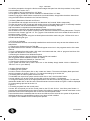
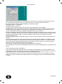
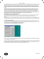
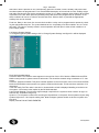
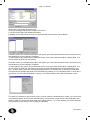
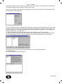
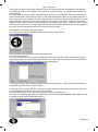
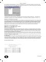
Page - 1 Windmill
Hardware Specification
In order to run Windmill or PanCom software the following system requirements must be satisfied:
1.1 PC Requirements
Pentium Processor running Windows 95 or later
The display must be run in a resolutions mode of 800 x 600 or greater.
Serial port Com1, Com2 or Com3
As some software takes priority over the serial ports, it must be ensured that any such software has been
terminated if using the same serial port as used by this software.
1.2 Fire Alarm Control Panel Requirements
This programming software works for the Millennium range of control and booster panels including the: EDA-M100
EDA-M150
EDA-M200
EDA-M300
EDA-M350.
All versions of software fitted in panels are supported.
1.3 Additional Equipment Required
In addition to the PC and control panel you will require a set of programming leads EDA-Q592. These
leads either plug into the front of the control panel using a 5 pin din connector or through the module port, a
20 way IDC connector labelled ‘Module Port’ on the processor PCB on the inside of the panels door.
The leads can not be copied easily as a printed circuit board is fitted inside the 9 way D Type connector
that plugs into the PC.
2.0 Introduction and Version Control
This section details any changes to software and manuals for the Windmill programming software
3.0 Navigating the CD
The supplied CD contains all the necessary set-up files for both Windmill and PanCom software.
Also included on this disk are various other features, including product datasheets, manuals and
photographs. Details on installing this software as well as accessing the other features included on
the disk are detailed in the following section:
3.1 Disk Structure
As can be seen the CD is made up of 7 main directories. The contents of each directory is detailed as follows:
datasheets: technical sheets for the EDA product range.
eda: installation files for DOS based software for panels.
edadet: installation files for DOS based software for device programming.
manual: user manuals for the EDA product range.
pancom: installation files for WINDOWS based panel downloading.
3_5_disk: installation files for transfer to 3.5" floppy disk.
photos: sales photos for the EDA product range.
jpg: photos in *.jpeg file format (lower resolution)
tif: photos in *.tif file format (higher quality)
windmill: installation files for WINDOWS based panel messages and options.
3_5_disk: installation files for transfer to 3.5" floppy disk.
Installation of program files along with viewing of the other resources will be dealt with in the following sections:
GD Systems
Page - 2 Windmill
3.2 Installing Program files
3.2.1 Installing Windmill from CD
· Before starting any installation ensure any other applications have terminated to avoid software conflicts.
· Insert the CD in the CD player.
· Using Windows Explorer or My Computer select the CD drive.
- usually D:
· Double click on the windmill directory.
· Contained in the windmill directory will be a file named SETUP.EXE
- typically assigned a 'computer' icon - but this will depend on your PC.
· Double click on this SETUP application and follow the on screen instructions.
· You will be warned to close any applications that are running.
- if you already have then click ok.
· You should then be prompted for the installation directory.
- we recommend that the system is installed in a directory:
C:\EDA
- This ensures any previous systems created using the original DOS based software are stored in the same
locations.
· Once you are satisfied with the installation directory click on the large button.
· SETUP will now install the program.
If you encounter error messages warning you of existing files this is probably due to a version of windmill
already installed on your PC. You will need to quit the set-up, un-install this older version:
start > settings > control panel > add/remove programs
Find Windmill (or PanCom) in the list provided then select it using a single click.
If you are certain you have selected the correct program, click add/remove program to remove this earlier
version.
3.2.2 Installing PanCom from CD
The installation of PanCom is very similar to the above installation of Windmill.
Instead of running the setup file contained in the windmill folder, simply follow the above instructions using
the setup file contained in the PanCom folder.
3.2.3 Installing Windmill software from 3.5" disks
For PC's not having a CD drive, installation is possible from 3.5" disks. However a PC with a CD drive is
required to first transfer the relevant files from the CD onto floppy disks. The procedure for copying the files
onto 3.5"disk is as follows:
· Format 3 x 3.5" disks.
· Open Windows Explorer or My Computer
· Open (double click) the CD drive (typically D:)
· Open the Windmill folder
· Open the 3_5_disk folder
Copying files:
· Select (single click) the folder titled DISK1
· At the top of the window is a toolbar click on Edit
· This should drop down a list of functions
· Click on Copy
· Now select the 3.5" floppy drive
· Go back to the toolbar and again click Edit
· Now click Paste.
· This should copy the folder DISK1 onto the 3.5" disk.
· Once this is complete remove this disk and label it 'Windmill Disk 1'
· Insert the next blank disk and repeat the above copying files: section for the folder titled DISK2.
· Repeat this until all the DISKx folders have been copied.
Once the software has been copied onto 3.5" disk the procedure for installing from the disks is again similar
to installing from CD. Simply insert disk 1, open the disk and contained in the folder disk 1 will be
SETUP.EXE. Double click on SETUP to run the installation procedure.
GD Systems
Page - 3 Windmill
You will be prompted to change the disk at various stages but apart from this the procedure is very similar
to that detailed in section 3.2.1.
3.2.4 Installing PanCom software from 3.5" disks
This is again very similar to the above installation of Windmill from 3.5" disks.
Instead of copying the DISK folders contained in the windmill folder, simply follow the above instructions
using the DISK folders contained in the PanCom Directory.
3.3 Viewing Datasheets, Manuals and Photos.
The datasheets and manuals are stored in the 'datasheet' and 'manual' folders respectively.
The files are stored in PDF format and will require the use of Acrobat Reader which, if not already installed
on your machine, can be downloaded free of charge from the following web site:
http://www.adobe.com/products/acrobat/readstep2.html
You are free to reproduce and distribute both the datasheets and the manuals.
Also included on the CD are photos of EDA products, these are intended for use by sales teams. The photos come in two formats *.jpg and *.tif. The *.jpg are a low resolution and hence smaller file size version of
the higher quality *.tif files.
Any brochures being made using the enclosed photos should be made using the *.tif files which are a
standard publishing file type.
4.0 To Run the Software
Once the software has been successfully installed there are three main ways to start the software as detailed below.
4.1 Running the Software from the Task Bar
By default whenever the software is installed it will appear as an icon in the programs section of the start
task bar.
To run the software from this location click ‘start’ in the bottom task bar, click on ‘programs’ and then click
on either the ‘Windmill’ or ‘PanCom’ icons.
4.2 Running the Software from Windows Explorer
Open windows explorer, open the directory where the file was installed.
(Our suggested default installation location is c:\EDA)
Double click on either the ‘Windmill’ or ‘PanCom’ icon.
4.1 Running the Software from the Desktop
If your system has been set-up with a short cut on the desktop simply double click the ‘Windmill’ or
‘PanCom’ icon on your desktop.
5.0 Using Windmill Software
5.1 Defining a new system.
In order to create a new system click on the ‘create new’ button. The screen will display blank panel and
device information as shown in figure 5.2. To change the settings go to section 5.4
5.2 Loading from an earlier system stored on a disk
To load data from a previous system saved on disk click on the ‘Load from disk’ button.
A screen allowing you to select a file from the disk as shown in figure 5.1 is displayed.
To change the directory click on the appropriate buttons until the correct directory appears. To select the
desired file double click on the file name. Data will load and a screen similar to Figure 5.2 will be displayed.
To change settings proceed to section 5.4
Figure 5.1
5.3 Loading a system from the control panel.
Connect the front panel port of the control panel to the PC and click on ‘Load from panel’ button. A
progress bar will be displayed as the data is loaded. If this fails try pressing the internal reset button on the
processor board of the control panel and re-click the ‘load from panel’ button.
Care should be taken to establish that the cause and effects are the same for the system in all panels as
individual panels may operate different relays in an alarm or fault condition.
This option is not available for the module port at present.
GD Systems
Page - 4 Windmill
5.0 Using Windmill Software
5.1 Defining a new system.
In order to create a new system click on the ‘create new’ button. The screen will display blank panel and
device information as shown in figure 5.2. To change the settings go to section 5.4
5.2 Loading from an earlier system stored on a disk
To load data from a previous system saved on disk click on the ‘Load from disk’ button.
A screen allowing you to select a file from the disk as shown in figure 5.1 is displayed.
To change the directory click on the appropriate buttons until the correct directory appears. To select the
desired file double click on the file name. Data will load and a screen similar to Figure 5.2 will be displayed.
To change settings proceed to section 5.4
Figure 5.1
5.3 Loading a system from the control panel.
Connect the front panel port of the control panel to the PC and click on ‘Load from panel’ button. A
progress bar will be displayed as the data is loaded. If this fails try pressing the internal reset button on the
processor board of the control panel and re-click the ‘load from panel’ button. Care should be taken to establish that the cause and effects are the same for the system in all panels as individual panels may operate different relays in an alarm or fault condition.This option is not available for the module port at present.
5.4 To Change Device Settings and/or Cause and Effects
Having created a new system, loaded the data from a disk or loaded data from a control panel the following
screen will be displayed. This screen may display information relating to the system being changed or be
blank if it is a new system. This screen is used to only display the settings. The screen details panel information with the panel number pre-fixed with ‘P’ in the unit number column. Device information can be displayed by scrolling past the panel details. Panels 1 to 50 are displayed first. To scroll either click and hold
on the scroll bar or drag the drag bar to the appropriate position.
Figure 5.2
5.4.1 Change Device Settings
If you require to change device settings, then the screen needs to be positioned to display the device
number. Use the scroll bar or drag bar to position to selector to the devices.
Devices do not have the unit number prefixed with a ‘P’. Once positioned, double click on the parameter of
the appropriate device to be changed. Figure 5.3 will be displayed
If you require to change the cause and effects for a particular device number, select the device number and
double click on the ‘Special’ row for the particular device. This will cause a screen as shown in figure 5.3 to
be displayed. If the device number is not correct then the up and down arrows can be used to reposition
the device number. It should be noted that any changes made prior to changing the device number will automatically be saved.
GD Systems
Page - 5 Windmill
Device Type The device type of the unit installed. To ensure correct operation this value must be correct.
The codes follow the product code. If you are unsure then the ‘X’ option must be used. Zone
The zone number must be programmed between the following values
EDA-M100 system 1 – 999 zones
EDA-M200 system 1-20 zones
Locations Text The device location text can be set using a maximum of 37 characters
Day/Night Mode On If analogue devices are being used (500 and 600 range of detectors) then for individual units the day night mode can be selected. In the global options the start and end time of this mode
can be selected and the sensitivity changed during these hours can be selected.
Sensitivity If analogue devices have been fitted *500 and 600 range of detectors) then the sensitivity can be
selected. The default is ‘Normal’ but if a higher sensitivity is required for computer rooms or high risk areas
the sensitivity should be set higher. If devices are fitted in hostile areas or roof voids then the lower
sensitivity should be set.
2nd Input Used If the 2nd input is being used this check box must be selected to allow a unit number to be
entered.
2nd Input Device Number If the 2nd input is used a device number must be assigned. This will be the device number displayed on the panel should the 2nd input detect an alarm condition. If not defined it will default to the next unit number provided the panel is put into the self learn mode. To ensure this operates
correctly the unit should always be assigned if being used.
Save and Exit To return to the previous screen this button must be pressed.
Once changes are made they are automatically saved and can only be changed back by re-typing the older
values.
5.4.2 Change Device Cause and Effects
If the cause and effects for a particular device need to be changed position the scroll bar to detail the appropriate unit number and double click on the column labelled ‘Special’ for the particular device. Screen 5.4
will be displayed. The cause and effects are listed in the following section.
If the device number is not correct then the up and down arrows can be used to reposition the device
number. It should be noted that any changes made prior to changing the device number will automatically
be saved.
GD Systems
Page - 6 Windmill
Location text The location text cannot be changed on this screen and is displayed for reference only.
Zone number The zone number cannot be changed on this screen and is displayed fore reference only.
Initial Delay: Setting the initial delay will cause the system to display an alarm condition immediately and
then delay for however many seconds set before operating any sounders or outputs. If any outputs or
sounders are required to operate immediately in the event of an alarm condition, this value should be set to
zero. The second delay can then be used to change the alarm operation after the delay period. Sounder
Circuits Each main control panel is fitted with 2 sounder circuits (Cct 1 & 2). By use of an expansion card
(EDA-510) this can be increased to 4 (Cct 3 & 4). In an alarm condition they can be programmed to switch
24V (On), pulse on for 1 second and off for 1 second (Int1), pulse on for 1 second and off for 2 seconds
(Int2) or not to operate (Off). The appropriate option box should be selected for the appropriate sounder
circuit. The booster panels can only have 2 sounder circuits (Cct 1 & 2) which if required can be modified (
a small hardware modification) to become auxiliary circuits (Aux 1 & 2) Aux. Relay Each main control panel
is fitted with two auxiliary relays with the capability of being expanded to four with an EDA- 510 interface
card. In an alarm condition for a device the relays can be individually programmed to operate (On) or not
operate (Off). Care should be taken as by default the aux 2 relay is for common fault and is fail safe. If this
is being used to signal an alarm condition the fault setting in the panel options must be amended. When
wiring this relay always bare in mind the fail-safe operation. The relay is normally closed in normal operation and will open in either a fire condition or fault condition (depending on programming) or a power supply
failure.
GD Systems
Page - 7 Windmill
Radio Sounders Tone The tone for the radio sounder can be set. The default tone is tone 4 (swept Tone). If
EDA-A910 hardwired sounders are being used to match the tone of the radio units then the tone for the
hardwired sounders is set inside the individual units. Radio Sounder Auxiliary If the radio sounders are fitted with auxiliary outputs or output devices are fitted then this should be checked to operate the auxiliary
output.
Radio Sounders Area If the radio sounders have been grouped in to areas then the system can be programmed to sound individual areas. The default is to sound all areas. If a separate area is required to
sound, then the areas should be entered into the fields. A maximum of three areas can be programmed to
sound for a single alarm condition. Values should be entered from left to right and if not used left as 0.
Second Delay Once the first delay has expired the second delay will commence if set. After this delay has
expired the cause and effects will operate as detailed in the corresponding settings.
See the previous section for the values required.
Which Panel - This is not implemented yet.
Store as Default Store the values set on the screen to temporary memory, to enable them to be loaded
back for other units. This enables common changes to be made to multiple devices quickly and
easily.
Set to Default If the ‘Store as Default’ button was used earlier in the session then those saved values can
be loaded into the current selected unit number. Select the unit number and click the ‘Set to Default’ button.
5.5 Change Panel Settings
To change panel settings position the scroll bar to display the appropriate panel number and double click
anywhere on the line of the appropriate panel number. Panel numbers are always preceded by a ‘P’ on the
list of devices. A screen similar to figure 5.5 will be displayed.
For a description of the relays available see section 5.4.1
Location Text The location text details the position of the control or booster panel in the building. Its length
has a maximum of 37 characters
Evacuate - When Evacuate is pressed on the corresponding panel the sounder circuits, auxiliary relays and
radio sounders will operate as programmed. For a more detailed description of the sounder circuits, auxiliary relays and radio sounders see the device programming section (5.4.1)
GD Systems
Page - 8 Windmill
Alert When Alert is pressed on the corresponding panel the sounder circuits, auxiliary relays and radio
sounders operate as programmed. For a more detailed description of the sounder circuits, auxiliary relays
and radio sounders see the device programming section (5.4.1) Relay operation silence alarm When Reset
is pressed on the fire alarm panel any auxiliary relays that have been programmed to operate in a fire
alarm condition will cancel. In order to cancel these when ‘Silence Alarm’ is pressed the appropriate
auxiliary box can be checked.
Fault Aux. Relay In the event of a common fault condition a relay can be programmed to operate by checking the appropriate relay box. The system defaults to Aux. 2 operating on a fault condition. Aux. 2 is a failsafe relay. The relay is normally closed in normal operation and will open in either a fault condition or a
power supply failure.
5.6 Change System Settings
To change the global system settings click in ‘Change System Settings’ and figure 5.6 will be displayed
Each field is detailed below.
Customer Name The customer name appears in the top line of the LCD of both the EDA-M100 and EDAM200 control panels in system normal or fault mode. This should be entered using a maximum of 17 characters.
Customer Telephone Number This phone number appears on the second line of the LCD on both the EDAM100 and EDA-M200 control panels in a system normal and fault mode. This should be a maximum of 12
characters.
Time Until Verify Fail This value is the time in minutes before a fault is displayed detailing a lost device on
the system. 270 minutes is the implied by the BS 5839 standard.
Logon Signal Strength The minimum signal strength required for the system to allow a device to logon on.
Devices only. EDA-M100 range only.
System 1-7,8-15 System numbers are set using the dip switches on the panel. Some systems require using
systems higher than 7 and require setting here. Note Analogue systems should not be set to system numbers 8-15.
Display Internal Fail NOT IMPLEMENTED
GD Systems
Page - 9 Windmill
Display Low Batteries NOT IMPLEMENTED
Timeout Values The system has many settings or operations, which after a predetermined period of time
automatically cancel. This is where these values are set. Refer to the EDA-M100 manual for descriptions of
these values
Analogue Global Options Only required for analogue systems that use the analogue range of detectors. %
level changes when changing from day to night mode. + sets the units more sensitive, - sets the units less
sensitive. The pre alarm level is a % of the alarm value and should be defaulted to 95% . The head dirty is
a percentage of the alarm level and should be set to approximately 85%.
Save as Default Once the default values are set they can be saved as the defaults and loaded for the next
new system. To do this click ‘Save as Default’
Load Defaults If previously the settings have been saved as default they can be reloaded into the system
by clicking ‘load default’.
Exit and Save To return to the main screen press exit and save. Any values changed on the screen will
now be stored. If there are any values that are incorrect they must be corrected before exiting this screen.
5.7 Saving Settings to Disk
Once the messages and cause and effects have been completed they should be saved to disk. As a precautionary measure it would be worth while saving the information to the disk drive on regular occasions
throughout entering lots of information in case of problems with the PC. The system does not auto-save the
work.
Click on ‘Save to Disk’ and the following screen will be displayed.
Select the appropriate directory. Type the file name to be saved or click on the existing file if to be over written and then click on the save button.
5.8 Sending Settings to Panel
When the messages and cause and effects have been programmed correctly, the information is required to
be downloaded into all the panels.
Messages and options are required to be loaded into display panels whereas only options are required to
be loaded into booster. This must be performed to ensure correct operation of the system. .
If only defaults are used (including zones) options do not require loading into panels.
Having clicked on the ‘Download to Panel’ button the screen as shown in figure 5.8 appears.
In order to download the correct information, the following parameters have to be set.
Messages/Options Allows the user to select whether to down load options, messages or both.
M100/M200 Select panel type being down loaded
Panel Port Select front panel port for the particular lead being used.
Com Port Select PC Comm port being used
Panel Software Select appropriate version of software
Status Information This details the amount of options/messages loaded
GD Systems
Page - 10 Windmill
When downloading settings to the EDA-M200 panel, the options and messages must be performed separately. Select messages first and download them to the panel. Then select options and download them to
the panel.
5.9 Print System Settings to Disk
In order to print the settings, the system allows the settings to be stored in a file on the computers disk
drive. This can then be imported into an editor or word-processor, formatted and then printed.
To Print Settings Click on the button labelled ‘Print to File’. A screen is displayed.
Click on the ‘Print’ button and a screen will be displayed as shown in Figure 5.9. Enter the file name and
press ‘Save’. It is recommended that a file type of .DOC is used.
To Edit the File Open the file in to a Word-processor or Text Editor or run Windows Explorer and double
click on the appropriate. This will automatically load the file into a program previously set up the PC.
If not refer to the windows help.
Figure 5.9
6.0 Using PANCOM Software:
In order to demonstrate the use of this software there will be two simple examples:
The first example will deal with a site called "college". We will step through the program using this software
to download data from the 3 panels on this site. We will then use this software analyse the data and produce a full report.
The second example will deal with a site called "townhall" where the data has already been downloaded. In
this example the software will simply be used to prepare a report using the files.
6.1 Example 1: "Collage" - downloading from panels.
Upon starting PANCOM you are presented with the screen shown below:
GD Systems
Page - 11 Windmill
Since we want to download from a panel click 'Download from Panels'
6.1.1 Site Information Screen
Clicking 'Download from Panels' you will be presented with the screen shown Below:
Our site name is 'College' so this is entered in the site name field. In the next field we enter the number of
panels on the system. In this example our system has 3 panels so this is entered.
Once the number of panels has been entered click continue. To return to the main screen click back.
Note : The site name is used as part of the file name at a later stage. With this in mind don't use special
characters ( * & ? £ ). E.g. bad site names would be:
*college*
college/new
@college
Also try and keep the site name short. This is not critical but it will aid compatibility with the old 'ProComm'
system. (- if your company no longer uses 'ProComm' then you are free to use more but try to keep below
20!)
Also the maximum number of panels on any system is 50. Attempting to enter more that this number will
generate an error.
6.1.2 Site Save Locations
The next screen we are presented with is as follows:
As can be seen the site name and number of panels enter on the previous screen is shown for confirmation. Also displayed is the default save location and filename.
As seen our default filename is c:\college.txt. This means that a download from panel 1 will be stored in
c:\college01.txt a download from panel 35 will be stored in c:\college35.txt.
To change any of the details simply click the corresponding button. If change of the save location is required the familiar save location box will appear:
GD Systems
Page - 12 Windmill
Simply select the location and click Save.
Once you are happy with the save location click next >>.
6.1.3 File Control and Panel Download Screens
Following on from the previous screen you are presented with the screen shown Below:
From this screen you can add new panels to the system, go to the panel download screen and remove any
downloads that you have already completed.
To add a panel to the system click on Add New Panel, in this case Panel 04 would be created. [Note: You
cannot remove a panel from the system]
From this screen you can add new panels to the system, go to the panel download screen and remove any
downloads that you have already completed.
To add a panel to the system click on Add New Panel, in this case Panel 04 would be created. [Note: You
cannot remove a panel from the system but you do not have to download from all the panels on the system. - so don't worry if there are more panels displayed than you actually have on the site!] To download
from a panel first highlight that panel in the left had box by clicking on it, we will select panel 1. Once this is
selected click on the Panel Download >> button, you will then be taken to the Panel Download screen:
The panel you selected on the previous screen is shown under the download from: caption. As can be seen
in the previous screen shot we have selected Panel 01. Also shown on this screen is the destination save
location. [Note: To change the panel simply click change panel?... or << back whereby you will be returned
to the previous screen and you can change you selection.]
GD Systems
Page - 13 Windmill
Providing the details shown are correct connect the PC to the module port of the panel, click continue with
the mouse and press the dump button inside the panel Twice.
After a few seconds the panel will start communicating with the PC and a progress bar will appear where
the continue button was previously:
Once the download has been completed click Next and you will be returned to the file control screen. Upon
returning to the file control screen the panel you have just downloaded from will be removed from the panels still on system list. A new file will be added to the Panel downloads complete list. In our example the
filename added will be "c:\College01.txt".
To quit the download click Abort download and you will be returned to the file control screen.
The above procedure is performed for the remaining two panels and upon returning from the download
screen for the final time the file control screen [Screen 2] should look like the screen shown below:
All the panels on the site have been downloaded from so click: Analyse Downloads>>
6.1.4 Data Analysis
The final analysis screen is shown below:
GD Systems
Page - 14 Windmill
Data analysis is made up of three main stages:
i) Processing of Downloaded Data,
ii) Correction of corrupted lines (if any),
iii) Report Generation.
At this stage files can be added or removed using the corresponding buttons.
Clicking on Process Files proceeds with the analysis.
6.1.4i File Processing
Upon processing the data from each file will be read and checked for corruption, if detected a new screen
will appear to deal with the corrupt line. Our example download has one corrupt line, shortly after clicking
process files the corruption screen appears to deal with this corrupt line.
6.1.4ii Corruption Correction
The corruption screen appears when the first instance of corruption is detected.
#
As can be seen it is made up of six main caption boxes:
1) Warning caption - confirming that your download files will not be altered.
2) Download file being read from.
3) Valid lines already read.
4) The original corrupted line contained in the file.
5) The correction attempted by the program - this is also where you can make corrections.
6) A sample line for you to base your corrections on.
Along with five user interface buttons:
1) Use >> is enabled only if the corrected line is valid, if clicked it substitutes the corrected line for the corrupt one.
2) Delete >> ignores the corrupt line, allowing the user to produce a report without correcting this line.
3) Skip >> keeps the corrupt line, preventing the user from generating a report.
4) Skip all >> same as the above but for all corrupt lines encountered
5) << Quit stops corruption analysis returning to main processing screen.
In our example the corrupted line is on device 13 (D:0013).
Comparing our original corrupted line with the sample line at the bottom of the screen shot we can see that
the problem is due to the missing hyphens between the T: and S:. The software has detected this and inserted the required number of hyphens and spaces. It has also checked that the now corrected line has
passed all the required validity checks, indicated by the fact that the Use >> button is enabled.
All we need to do is check that the important details such as device number, and signal strength have not
been changed.
GD Systems
Page - 15 Windmill
If the corrected line did not pass the validity checks or was altered by the user in such a way that it no
longer passed its validity checks then the Use >> button would be de-activated until the line passed these
checks.
For more information on corrupt files see Appendix A.
Once the processing is completed we are informed that there is no uncorrected
corruption and presented with a screen similar to the one below:
As can be seen although it has been corrected the original corrupted line for device 13 is still shown in the
white text box.
To inform the user that it has been corrected the software adds a ' C ' at the end of the line.
This is also true for the instances where the user has selected to delete or skip a corrupt line, a 'D' or '*S*'
being added respectively.
If there is uncorrected corruption contained in your source files that has been skipped you will not be given
the option of generating a report. Again for more information on corruption see Appendix A.
Provided this is not the case (there is either no corruption or it has been corrected/deleted) then the user is
given the option of viewing the raw data or producing a report, as detailed in the next section.
6.1.4iii Report Generation
Once the processing and correction of source file data (if required) has been completed the process files
button disappears and you are presented with three new options:
1) Raw Data
2) Full Report
3) Weak Strengths Only
Depending on the size of the system being analysed the raw data option will show either on the screen, or
saved to a file, the data it will use for the creation of its report. If displayed the raw data can be saved using
the Save Text >> button or printed using the Print Text >> button.
The full report option will generate a listing as follows:
First the files used in the analysis along with their creation/modification date are displayed. Then each device and its type (as stored by the last panel on the system) is shown.
Included with each device is the panel with the highest communication strength to
this device.
GD Systems
Page - 16 Windmill
If this highest strength is below the standard 37 then two warning stars are displayed after the strength.
The highest strength is also flagged if it is stored as 0, this time using a '-?', to indicate that it may be a
panel anomaly.
The highest panel strength is again included along with the next four highest in a list of the five highest
panel communication strengths for this device. The weak strengths only option is very similar to the full report except that you are prompted to enter a filter strength. Only devices where the highest panel communication strength is below this value will be displayed in the report. In all report screens the information
displayed can be saved to a file or printed using the corresponding Save Text >> and Print Text >> buttons
at the bottom of the screen. For large systems where the report is automatically saved and not displayed a
text editor such as notepad must be used to view and print the report.
6.2 Example 2: "townhall" using existing files
As for the previous example PANCOM opens with the screen shown below:
Since we want to use existing files click 'Use existing files'
6.2.1 File Control Screen
As can be seen this file control screen is slightly different to the file control screen observed when downloading from panels. The panel list has been disabled, as has the add new panel and Panel Download >>
buttons. These features are not required when using existing files.
To add the previously downloaded files simply click Add Existing File(s)... And you will be presented with
the familiar open files screen shown overleaf:
To add a file click on it then click open. To add more than one file at a time simply hold down the Ctrl key
on the keyboard and click each file you want to download.
[If you accidentally click on the wrong file clicking on it again will de-select it.]
Once you have selected all the files you require click open and they will be added to the list. More files can
be added by again clicking Add Existing File(s)...
GD Systems
Page - 17 Windmill
Our example uses townhall files 1, 2 and 3. As stated these are selected by holding the control key and
selecting each file. Upon clicking Open you will be returned back to the control screen where the selected
files will be displayed in the downloaded files list.
If required, files can be removed by selecting them on the list and clicking remove file.... Once all the required files are present click on Analyse Downloads >> and follow the steps in Example 1 section 5.1.4.
Appendix A: PANCOM File Corruption
File corruption is where the data stored in a file is different to the data that is expected. The corruption that
occasionally effects EDA panel downloads is a loss in the synchronisation between the panel and the PC
being downloaded to. The result is almost always a loss of a small portion of the data. EDA device downloads have two formats, one for the dual frequency M100 system and another for the single frequency
M200 system. These formats are shown below and also in the two attached download examples.
M100 lines are of the following format:
D:0001 T:----------- S:20 A50 I-- F-- R-- DEVICE
M200 lines follow this similar format:
D0001 T01 S54 SMOKE T01
The numbers following D in both cases indicate the device number, the numbers following the S indicate
signal strength. More often that not corruption consists of a few missing characters which upon user analysis can easily be inserted. Occasionally the corruption may cause the loss of whole lines of data in which
case another panel download is recommended.
In order to pass the corruption check the test characters from the line must be in the correct position relative to the start of the line, hence a missing hyphen (-) between the T: and S: would cause the S character
to shift left - failing the corruption check.
A character inserted at the start of the line would also cause the line to fail since all test characters would
be shifted right.
Corrections made to corruption using the PANCOM software are only temporary and need to be performed
each time the data is processed. For a more permanent correction the source file should be opened using
a text editor such as NOTEPAD and corrected, failing that another download should correct the problem.
Example M100 Download:
GD Systems
Page - 18 Windmill
Example M200 Download
GD Systems