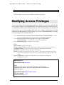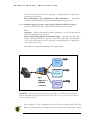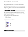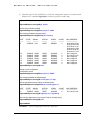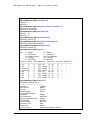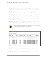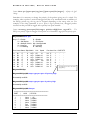
1
MAGNUM 6K FAMILY OF SWITCHES
Managed Network Software (MNS)
MNS-6K-SECURE 14.1.4 and MNS-6K 4.1.4
CLI User Guide
Preface
This guide describes how to use the Command Line Interface (CLI) for the Magnum
6K family of switches. For the Web Management Interface please refer to the Web
Management Guide.
Some simple guidelines which will be useful for configuring and using the Magnum
6K family of switches If you need information on a specific command in the CLI, type the
command name after you type the word “help” (help <command> ) or just
type <command> [Enter].
If you need information on a specific feature in Web Management Interface,
use the online help provided in the interface.
If you need further information or data sheets on GarrettCom Magnum 6K
family of switches, refer to the GarrettCom web links at:
http://www.garrettcom.com/managed_switches.htm (except MP62 switch shown on the page)
GarrettCom Inc.
47823 Westinghouse Drive
Fremont, CA 94539-7437
Phone (510) 438-9071• Fax (510) 438-9072
Email – Tech support – [email protected]
Email – Sales – [email protected]
WWW – http://www.garrettcom.com/
i
Trademarks
GarrettCom Inc. reserves the right to change specifications, performance characteristics
and/or model offerings without notice. GarrettCom, Magnum, S-Ring, Link-Loss-Learn,
Converter Switch, Convenient Switch and Personal Switch are trademarks and Personal Hub
is a registered trademark of GarrettCom, Inc.
NEBS is a registered trademark of Telcordia Technologies.
UL is a registered trademark of Underwriters Laboratories.
Ethernet is a trademark of Xerox Corporation.
Copyright © 2007 GarrettCom, Inc. All rights reserved. No part of this publication may be
reproduced without prior written permission from GarrettCom, Inc.
Printed in the United States of America.
Part #: 84-00131
PK-062808
ii
Table of Contents
1 – Conventions Followed ............................................................... 19
Flow of the User Guide .......................................................... 21
2 – Getting Started ............................................................................ 23
Before starting .......................................................................... 23
MNS-6K Software Updates ....................................................... 24
Console connection ................................................................. 24
Console setup............................................................................ 25
Console screen .......................................................................... 25
Logging in for the first time ................................................... 26
Setting the IP parameters ........................................................ 26
Privilege levels........................................................................... 29
Operator Privileges...................................................................... 30
Manager Privileges ....................................................................... 30
User management..................................................................... 30
Add User ....................................................................................... 30
Delete User ................................................................................... 31
Modify Password ......................................................................... 31
Modify the Privilege Level ......................................................... 31
Modifying Access Privileges....................................................... 32
Help ............................................................................................ 34
Displaying Help for an Individual Command ......................... 34
Viewing options for a command ............................................... 34
Context help ................................................................................. 35
Exiting ........................................................................................ 36
iii
Upgrading to MNS-6K-SECURE ......................................... 36
List of commands in this chapter .......................................... 37
3 – IP Address and System Information..................................... 39
IP Addressing ............................................................................... 39
Importance of an IP address .................................................. 39
DHCP and bootp ........................................................................ 40
Bootp Database ........................................................................... 40
Configuring Auto/DHCP/Bootp/Manual ............................. 41
Using Telnet ................................................................................. 42
Using SSH..................................................................................... 44
Domain Name System (DNS) ............................................... 48
Setting serial port parameters ................................................. 50
System parameters.................................................................... 50
Date and time............................................................................ 52
Network time (SNTP Client) ................................................. 53
Network time (SNTP Server) ................................................. 54
Saving and loading configuration .......................................... 54
Config files.................................................................................... 58
Script files ..................................................................................... 60
Displaying configuration ......................................................... 62
Displaying or hiding passwords ............................................. 64
Erasing configuration .............................................................. 65
Displaying Serial Number ....................................................... 66
List of commands in this chapter .......................................... 67
Other commands ..................................................................... 70
4 – IPv6 .................................................................................72
Assumptions ................................................................................. 72
Introduction to IPv6 ................................................................ 72
What’s changed in IPV6? ........................................................ 73
IPv6 Addressing ....................................................................... 73
iv
Configuring IPv6 ...................................................................... 74
List of commands in this chapter .......................................... 75
5 – DHCP Server ..................................................................77
Modes of Operation ................................................................ 78
Technical Details ...................................................................... 79
DHCP Discovery ..................................................................... 79
DHCP Offers ........................................................................... 80
DHCP Request ......................................................................... 80
DHCP Acknowledgement ...................................................... 80
DHCP Information ................................................................. 81
DHCP Release .......................................................................... 81
Client Configuration ................................................................ 81
MNS-6K-SECURE Implementation .................................... 81
List of commands in this chapter .......................................... 83
6 – SNTP Server ...................................................................84
SNTP - prerequisites ................................................................... 84
Background ............................................................................... 84
Stratum clocks........................................................................... 85
MNS-6K-SECURE Implementation .................................... 87
List of commands in this chapter .......................................... 88
7 – Access Considerations ....................................................89
Securing access ............................................................................. 89
Passwords .................................................................................. 89
Port Security .............................................................................. 90
Network security.......................................................................... 90
Configuring Port Security ........................................................... 90
Syslog and Logs ........................................................................ 96
Authorized managers .............................................................102
List of commands in this chapter ........................................103
v
8 – Access Using RADIUS ................................................. 106
RADIUS ..................................................................................... 106
802.1x .......................................................................................106
Configuring 802.1x.................................................................109
List of commands in this chapter ........................................114
9 – Access Using TACACS+ .............................................. 116
TACACS – flavors and history ................................................ 116
TACACS+ Flow.....................................................................117
TACACS+ Packet ..................................................................118
Configuring TACACS+ ........................................................118
List of commands in this chapter ........................................120
10 – Port Mirroring and Setup ............................................ 122
Port monitoring and mirroring ................................................ 122
Port mirroring .........................................................................122
Port setup ................................................................................123
Speed settings ............................................................................. 124
Flow Control .............................................................................. 125
Back Pressure ............................................................................. 126
Broadcast Storms ....................................................................... 128
Preventing broadcast storms ................................................129
Port Rate limiting for broadcast traffic ...............................130
List of commands in this chapter ........................................130
11 – VLAN .......................................................................... 132
Why VLANs? ............................................................................. 132
Creating VLANs.....................................................................134
Private VLANs .......................................................................135
Using VLANs .........................................................................136
List of commands in this chapter ........................................145
12 – Spanning Tree Protocol (STP) .................................... 147
STP features and operation ...................................................... 147
vi
Using STP ................................................................................148
List of commands in this chapter ........................................158
13 – Rapid Spanning Tree Protocol (RSTP) ...................... 159
RSTP concepts ........................................................................... 159
Transition from STP to RSTP .............................................160
Configuring RSTP ..................................................................161
List of commands in this chapter ........................................172
14 – S-Ring™ and Link-Loss-Learn™ (LLL) .................... 174
S-Ring and LLL concepts ......................................................... 175
Comparing resiliency methods .............................................176
RSTP/STP Operation without S-Ring ...............................177
RSTP/STP Operation with S-Ring .....................................179
LLL with S-Ring .....................................................................181
Ring learn features..................................................................181
Configuring S-Ring ................................................................181
List of commands in this chapter ........................................185
15 – Dual-Homing .............................................................. 187
Dual-Homing concepts ............................................................ 187
Dual-Homing Modes .............................................................190
Configuring Dual-Homing ...................................................190
List of commands in this chapter ........................................192
16 – Link Aggregation Control Protocol (LACP) ............... 193
LACP concepts .......................................................................... 193
LACP Configuration..............................................................194
List of commands in this chapter ........................................204
17 – Quality of Service ........................................................ 205
QoS concepts ............................................................................. 205
DiffServ and QoS...................................................................206
IP Precedence .........................................................................207
vii
Configuring QoS ....................................................................208
List of commands in this chapter ........................................213
18 – IGMP ........................................................................... 214
IGMP concepts .......................................................................... 214
IGMP-L2 .................................................................................218
Configuring IGMP .................................................................221
List of commands in this chapter ........................................228
19 – GVRP........................................................................... 230
GVRP concepts ......................................................................... 230
GVRP Operations..................................................................231
Configuring GVRP ................................................................235
GVRP Operations Notes ......................................................237
List of commands in this chapter ........................................238
20 – SNMP .......................................................................... 239
SNMP concepts ......................................................................... 239
Traps.........................................................................................241
Standards .................................................................................241
Configuring SNMP ................................................................242
Configuring RMON ..............................................................251
List of commands in this chapter ........................................252
21 – Miscellaneous Commands .......................................... 256
Alarm Relays ...........................................................................256
Email ........................................................................................260
Serial Connectivity .................................................................265
Banner Message ......................................................................266
Miscellaneous commands .....................................................267
Prompt .....................................................................................269
Ping ...........................................................................................270
FTP modes ..............................................................................271
viii
System Events .........................................................................272
MAC Address Table ..............................................................277
List of commands in this chapter ........................................278
APPENDIX 1 - Command listing by Chapter .................. 281
Chapter 2 – Getting Started..................................................281
Chapter 3 – IP Address and System Information .............282
Chapter 4 – IPv6 ....................................................................286
Chapter 5 – DHCP Server ....................................................286
Chapter 6 – SNTP Server .....................................................287
Chapter 7 – Access Considerations .....................................287
Chapter 8 – Access Using Radius ........................................289
Chapter 9 – Access using TACACS+ .................................290
Chapter 10 – Port mirroring and setup ..............................291
Chapter 11 - VLAN ...............................................................291
Chapter 12 – Spanning Tree Protocol (STP) .....................292
Chapter 13 – Rapid Spanning Tree Protocol .....................293
Chapter 14 – S-Ring and Link-Loss-Learn ........................294
Chapter 15 – Dual-Homing ..................................................295
Chapter 16 – Link Aggregation Control Protocol (LACP)295
Chapter 17 – Quality of Service ...........................................296
Chapter 18 - IGMP ................................................................296
Chapter 19 - GVRP ...............................................................297
Chapter 20 – SNMP ..............................................................298
Chapter 21 – Miscellaneous Commands ............................300
APPENDIX 2 - Commands sorted alphabetically ............ 303
APPENDIX 3 - Daylight Savings ...................................... 326
Daylight Savings Time ...........................................................326
APPENDIX 4 – Browser Certificates................................. 328
Certificates ...............................................................................328
ix
Using Mozilla Firefox (ver. 3.x) ...........................................329
Using Internet Explorer (ver 7.x) ........................................333
Using Other Browsers ...........................................................334
APPENDIX 5 – Updating MNS-6K Software.................... 335
1. Getting Started ...................................................... 336
Selecting the proper version .....................................337
Downloading the MNS-6K software ......................337
Next steps ....................................................................341
2. Preparing to load the software .............................. 342
Accessing the switch ..................................................342
Serial Connection ......................................................... 342
Network Access ........................................................... 343
Saving the Configuration ...........................................343
Serial Connection ......................................................... 344
Network Access ........................................................... 346
Next steps ....................................................................347
3. Loading the MNS-6K software ............................. 348
Before loading the MNS-6K software ....................348
Accessing the switch ..................................................348
Serial Connection ......................................................... 349
Network Access ........................................................... 350
Next steps ....................................................................351
4. (Optional Step) Restoring the configuration ........ 352
Accessing the switch ..................................................352
Reloading the configuration......................................352
Updating boot code over the network ....................353
Index ................................................................................... 355
x
List of Figures
FIGURE 1 - HyperTerminal screen showing the serial settings ................................................................. 25
FIGURE 2 - Prompt indicating the switch model number as well as mode of operation – note the
commands to switch between the levels is not shown here. ............................................................. 26
FIGURE 3 – As the switch tries to determine its mode of operation and its IP address, it may
assign and release the IP address a number of times. A continuous ping to the switch will
show an intermittent response ..................................................................................................... 27
FIGURE 4 - Setting IP address on the switch ......................................................................................... 28
FIGURE 5 - Rebooting the switch........................................................................................................... 28
FIGURE 6 - Viewing the basic setup parameters. You can use ‘show setup’ or ‘show sysconfig’ to
view setup parameters ................................................................................................................ 29
FIGURE 7 - Switching users and privilege levels. Note the prompt changes with the new privilege
level. ......................................................................................................................................... 30
FIGURE 8 - Adding a user with Manager level privilege ........................................................................ 31
FIGURE 9 - Deleting a user.................................................................................................................. 31
FIGURE 10 - Changing the password for a specific user ......................................................................... 31
FIGURE 11 - Changing the privilege levels for a user .............................................................................. 32
FIGURE 12 – Creating user access privileges .......................................................................................... 33
FIGURE 13 – Creating user access privileges .......................................................................................... 33
FIGURE 14 - Help command .............................................................................................................. 34
FIGURE 15 - Help for a specific command ........................................................................................... 34
FIGURE 16 - Options for the ‘show’ command ...................................................................................... 35
FIGURE 17 - Listing commands available (at the operator level) ............................................................ 35
FIGURE 18 - Listing commands starting with a specific character .......................................................... 35
FIGURE 19 - Listing commands options – note the command was not completed and the TAB
key completed the command. ...................................................................................................... 36
FIGURE 20 – logout command .............................................................................................................. 36
FIGURE 21 – Upgrading to MNS-6K-SECURE ............................................................................... 37
FIGURE 22 - Checking the IP settings.................................................................................................. 40
FIGURE 23 - Changing the boot mode of the switch ............................................................................... 42
xi
FIGURE 24 - Changing telnet access – note in this case, the enable command was repeated without
any effect to the switch ................................................................................................................ 42
FIGURE 25 - Reviewing the console parameters – note telnet is enabled .................................................. 43
FIGURE 26 - Example of a telnet session ............................................................................................. 43
FIGURE 27 – managing and viewing multiple telnet sessions .................................................................. 44
FIGURE 28 – setting up ssh – since telnet sends the information in clear text, make sure that
telnet is disabled to secure the switch. Do not telnet to the switch to disable telnet. Preferred
method is to do that via the console or using SWM. The client access is not shown here.
Commonly an application like PUTTY is used to access the switch via ssh. Use the show
console command to verify telnet is turned off............................................................................... 48
FIGURE 29 – Use of DNS .................................................................................................................. 49
FIGURE 30 - Querying the serial port settings ....................................................................................... 50
FIGURE 31 - System parameters using the show setup command. Most parameters here cannot be
changed ..................................................................................................................................... 51
FIGURE 32 - System parameters using the show sysconfig command. Most parameters here can be
changed. .................................................................................................................................... 51
FIGURE 33 - Setting the system name, system location and system contact information ........................... 52
FIGURE 34 - Setting the system date, time and time zone ...................................................................... 52
FIGURE 35 - Setting the system daylight saving time ............................................................................. 53
FIGURE 36 - Setting up SNTP services ............................................................................................... 54
FIGURE 37 - Saving the configuration on a tftp server ........................................................................... 55
FIGURE 38 – Based on the sftp, ftp, tftp or xmodem commands – the MNS-6K based switch can
upload or download different types of files and images .Other files such as log files, hosts file
can also be saved or loaded onto a switch .................................................................................... 57
FIGURE 39 – commands to save the configuration using ftp. Similar options will be specified using
tftp etc. When using the ftp command, use the host command discussed later in this section
to define the ftp server ................................................................................................................ 58
FIGURE 40 – Contents of the config file................................................................................................. 59
FIGURE 41 – Example of Script file. Note all the commands are CLI commands. This script
provides insights into the configuration of Magnum MNS-6K settings. GarrettCom
recommends that modifications of this file and the commands should be verified by the User
in a test environment prior to use in a "live" production network................................................. 61
FIGURE 42 – Creating host entries on MNS-6K .................................................................................. 62
FIGURE 43 – Enabling or disabling the pagination ............................................................................... 62
FIGURE 44 – ‘show config’ command output ................................................................................... 63
FIGURE 45 – displaying specific modules using the ‘show config’ command ....................................... 64
xii
FIGURE 46 – displaying configuration for different modules. Note – multiple modules can be
specified on the command line ..................................................................................................... 64
FIGURE 47 – Hide or display system passwords .................................................................................... 65
FIGURE 48 – Erasing configuration without erasing the IP address ....................................................... 66
FIGURE 49 – Display the serial number, factory code and other relevant setup information ..................... 66
FIGURE 50 – Configuring IPv6 ............................................................................................................ 75
FIGURE 51 – Setting up DHCP Server on MNS-6K-SECURE ........................................................ 83
FIGURE 52 – Different Stratum NTP servers ....................................................................................... 86
FIGURE 53 – Using the SNTP commands ........................................................................................... 87
FIGURE 54 – Changing password for a given account ............................................................................ 89
FIGURE 55 – Port security configuration mode ...................................................................................... 90
FIGURE 56 – Port security configuration mode ...................................................................................... 91
FIGURE 57 – Port security – allowing specific MAC addresses on a specified port. (No spaces
between specified MAC addresses) ............................................................................................. 92
FIGURE 58 – Port security - the port learns the MAC addresses. Note – a maximum of 200
MAC addresses can be learnt per port and a maximum of 500 per switch. Also, the
‘action’ on the port must be set to none before the port ‘learns’ the MAC address
information. .............................................................................................................................. 92
FIGURE 59 – Enabling and disabling port security ............................................................................... 92
FIGURE 60 – Viewing port security settings on a switch. On port 9, learning is enabled. This port
has 6 stations connected to it with the MAC addresses as shown. Other ports have
learning disabled and the MAC addresses are not configured on those ports ................................ 93
FIGURE 61 – Enabling learning on a port. Note – after the learning is enabled, the port security
can be queried to find the status of MAC addresses learnt. If there were machines
connected to this port, the MAC address would be shown on port 11 as they are shown on
port 9 ....................................................................................................................................... 93
FIGURE 62 – Allowing specific MAC address on specific ports. After the MAC address is
specified, the port or specific ports or a range of ports can be queried as shown .............................. 94
FIGURE 63 – Removing a MAC address from port security .................................................................. 94
FIGURE 64 – Setting the logging on a port ............................................................................................ 94
FIGURE 65 – Steps for setting up port security on a specific port ............................................................ 95
FIGURE 66 – Show log and clear log command. Note the logs are in the syslog format. The syslog
commands are also displayed .................................................................................................... 101
FIGURE 67 – Steps to allow deny or remove specific services ................................................................. 103
FIGURE 68 – 802.1x network components ......................................................................................... 107
FIGURE 69 – 802.1x authentication details ....................................................................................... 108
xiii
FIGURE 70 – securing the network using port access ............................................................................ 113
FIGURE 71 – Flow chart describing the interaction between local users and TACACS
authorization .......................................................................................................................... 117
FIGURE 72 – TACACS packet format ............................................................................................. 118
FIGURE 73 – Configuring TACACS+ ............................................................................................. 120
FIGURE 74 – Enabling port mirroring ............................................................................................... 123
FIGURE 75 – Port setup ..................................................................................................................... 124
FIGURE 76 – Setting up back pressure and flow control on ports.......................................................... 128
FIGURE 77 – Setting up broadcast storm protection. Also shows how the threshold can be lowered
for a specific port ..................................................................................................................... 130
FIGURE 78 – VLAN as two separate collision domains. The top part of the figure shows two
“traditional” Ethernet segments. .............................................................................................. 132
FIGURE 79 – Ports can belong to multiple VLANs. In this figure a simplistic view is presented
where some ports belong to VLANs 1, 2 and other ports belong to VLANs 2,3. Ports
can belong to VLANs 1, 2 and 3. This is not shown in the figure. ......................................... 133
FIGURE 80 – routing between different VLANs is performed using a router such as a Magnum
DX device or a Layer 3 switch (L3-switch) ............................................................................. 134
FIGURE 81 – configuring VLANs on Magnum 6K switch................................................................. 135
Figure 82 – STP default values – refer to next section “Using STP” for more detailed
explanation on the variables .................................................................................................... 148
FIGURE 83 – Viewing STP configuration .......................................................................................... 149
FIGURE 84 – STP Port status information......................................................................................... 150
FIGURE 85 – Enabling STP ............................................................................................................. 152
FIGURE 86 – Configuring STP parameters ........................................................................................ 158
FIGURE 87 – Enabling RSTP and reviewing the RSTP variables ...................................................... 163
FIGURE 88 – Reviewing the RSTP port parameters ............................................................................ 164
Figure 89 – Path cost as defined in IEEE 802.1d (STP) and 802.1w (RSTP) ............................... 165
FIGURE 90 – RSTP information from a network with multiple switches. Note the “show stp
ports” command can be executed from the manager level prompt or from rstp configuration
state as shown in the screen captures earlier. ............................................................................. 166
FIGURE 91 – Configuring RSTP on MNS-6K .................................................................................. 171
FIGURE 92 – Normal RSTP/STP operations in a series of switches. Note – this normal status
is designated RING_CLOSED ............................................................................................ 178
FIGURE 93 – A fault in the ring interrupts traffic. The blocking port now becomes forwarding so
that traffic can reach all switches in the network Note – the mP62 as well as the ESD42
switches support LLL and can participate in S-Ring as an access switch .................................. 179
xiv
FIGURE 94 – More than one S-Ring pair can be selected and more than one S-Ring can be
defined per switch. Note – the mP62 as well as the ES42 switches support LLL and can
participate in S-Ring as an access switch .................................................................................. 180
FIGURE 95 – Activating S-Ring on the switch .................................................................................... 182
FIGURE 96 – S-Ring configuration commands for root switch .............................................................. 184
FIGURE 97 – Link Loss Learn (LLL) setup. Setup LLL on ports connected to other switches
participating in S-Ring ............................................................................................................ 185
FIGURE 98 – Dual-homing using ESD42 switch and Magnum 6K family of switches. In case of
a connectivity break – the connection switches to the standby path or standby link ..................... 188
FIGURE 99 – Dual-homing using Magnum 6K family of switches. Note the end device (video
surveillance camera) can be powered using PoE options on Magnum 6K family of switches.
In case of a connectivity break – the connection switches to the standby path or standby
link ........................................................................................................................................ 188
FIGURE 100 – Using S-Ring and dual-homing, it is possible to build networks resilient not only
to a single link failure but also for one device failing on the network .......................................... 189
FIGURE 101 – configuring dual-homing ............................................................................................... 191
FIGURE 102 – Some valid LACP configurations................................................................................ 195
FIGURE 103 – an incorrect LACP connection scheme for Magnum 6K family of switches. All
LACP trunk ports must be on the same module and cannot span different modules. ................. 195
FIGURE 104 – In this figure, even though the connections are from one module to another, this is
still not a valid configuration (for LACP using 4 ports) as the trunk group belongs to two
different VLANs. .................................................................................................................. 195
FIGURE 105 - In the figure above, there is no common VLAN between the two sets of ports, so
packets from one VLAN to another cannot be forwarded. There should be at least one
VLAN common between the two switches and the LACP port groups. ................................... 196
FIGURE 106 – This configuration is similar to the previous configuration, except there is a
common VLAN (VLAN 1) between the two sets of LACP ports. This is a valid
configuration............................................................................................................................ 197
FIGURE 107 – In the architecture above, using RSTP and LACP allows multiple switches to be
configured together in a meshed redundant link architecture. First define the RSTP
configuration on the switches. Then define the LACP ports. Then finally connect the ports
together to form the meshed redundant link topology as shown above. ......................................... 197
FIGURE 108 – LACP, along with RSTP/STP brings redundancy to the network core or
backbone. Using this reliable core with a dual-homed edge switch brings reliability and
redundancy to the edge of the network ....................................................................................... 198
FIGURE 109 – This architecture is not recommended............................................................................ 199
FIGURE 110 – Creating a reliable infrastructure using wireless bridges (between two facilities) and
LACP. “A” indicates a Wi-Fi wireless Bridge or other wireless Bridges. ................................. 200
FIGURE 111 – Configuring LACP .................................................................................................... 202
xv
FIGURE 112 – The network for the ‘show lacp’ command listed below .................................................. 203
FIGURE 113 – LACP information over a network ............................................................................. 204
FIGURE 114 – ToS and DSCP ......................................................................................................... 206
FIGURE 115 - IP Precedence ToS Field in an IP Packet Header......................................................... 207
FIGURE 116 - Port weight settings and the meaning of the setting ......................................................... 209
FIGURE 117 – QoS configuration and setup ........................................................................................ 213
FIGURE 118 – IGMP concepts – advantages of using IGMP.............................................................. 216
FIGURE 119 – IGMP concepts – Isolating multicast traffic in a network ............................................. 217
FIGURE 120 - In a Layer 2 network, an IGMP multicast traffic goes to all the nodes. In the
figure, T1, a surveillance camera, using multicast, will send the traffic to all the nodes - R1
through R6 - irrespective of whether they want to view the surveillance traffic or not. The
traffic is compounded when additional cameras are added to the network. End result is that
users R1 through R6 see the network as heavily loaded and simple day to day operations
may appear sluggish. ................................................................................................................ 219
FIGURE 121 - Using IGMP-L2 on Magnum 6K family of switches, a Layer 2 network can
minimize multicast traffic as shown above. Each switch has the IGMPL2 turned on.
Each switch can exchange the IGMP query message and respond properly. R4 wants to
view surveillance traffic from T1. As shown by (1), a join request is sent by R4. Once the
join report information is exchanged, only R4 receives the video surveillance traffic, as
shown by (2). No other device on the network gets the video surveillance traffic unless they
issue a join request as well. ...................................................................................................... 220
FIGURE 122 – Enabling IGMP and query the status of IGMP ......................................................... 222
FIGURE 123 – Displaying IGMP groups ........................................................................................... 223
FIGURE 124 – Configuring IGMP..................................................................................................... 226
FIGURE 125 – Adding broadcast groups using the group command ...................................................... 227
FIGURE 126 - Setting IGMP-L2 ....................................................................................................... 228
FIGURE 127 – GVRP operation – see description below ..................................................................... 231
FIGURE 128 – VLAN Assignment in GVRP enabled switches. Non GVRP enabled switches
can impact VLAN settings on other GVRP enabled switches................................................. 232
FIGURE 129 – Port settings for GVRP operations ............................................................................. 233
FIGURE 130 – Command to check for dynamically assigned VLANs ................................................ 234
FIGURE 131 – Converting a dynamic VLAN to a static VLAN ..................................................... 234
FIGURE 132 – GVRP options ........................................................................................................... 235
FIGURE 133 – GVRP configuration example .................................................................................... 237
FIGURE 134 – Configuring SNMP – most of the command here are SNMP v3 commands ................ 251
FIGURE 135 – Configuring RMON groups ........................................................................................ 252
xvi
FIGURE 136 – Predefined conditions for the relay ................................................................................ 257
FIGURE 137 – Setting up the external electrical relay and alerts .......................................................... 260
FIGURE 138 – setting SMTP to receive SNMP trap information via email ......................................... 265
FIGURE 139 – Optimizing serial connection (shown for Hyper Terminal on Windows XP). The
highlighted fields are the ones to change as described .................................................................. 265
FIGURE 140 – setting up a banner message ......................................................................................... 267
FIGURE 141 – History commands ....................................................................................................... 269
FIGURE 142 – Setting custom prompts ................................................................................................ 270
FIGURE 143 – Using the ping command ............................................................................................. 271
FIGURE 144 - Setting the FTP mode .................................................................................................. 271
FIGURE 145 – Event log shown on the screen ...................................................................................... 273
FIGURE 146 – Using exportlog to export the event log information ...................................................... 274
FIGURE 147 – Listing of severity - sorted by subsystem and severity ..................................................... 277
FIGURE 148 – Display of the internal switching decision table ............................................................. 278
FIGURE 149 – On finding a mismatch between the certificate and the accesses site, Mozilla
Firefox pops the window. Note – the site was accessed using the IP address. Typically, sites
accessed by their IP address will trigger this mismatch ............................................................... 329
FIGURE 150 – Mozilla Firefox tries to warn the user again about the dangers of sites with
improper certificates ................................................................................................................. 330
FIGURE 151 – Firefox forces you to get the certificate before it lets you access the site ............................. 331
FIGURE 152 – Here, you can view the certificate, permanently make an exception and confirm the
exception. The locations to do those are identified in this figure .................................................. 332
FIGURE 153 – Self signed certificate from GarrettCom Inc for MNS-6K............................................. 333
FIGURE 154 – Using IE 7 ................................................................................................................ 334
FIGURE 155 – Accessing the GarrettCom site for download. ............................................................... 339
FIGURE 156 – Select the proper version to use after successful login ...................................................... 340
FIGURE 157 – Navigate to MNS-6K folder to download the latest MNS-6K software and the
release notes ............................................................................................................................. 340
FIGURE 158 – Use the copy command to copy the files to the proper location ........................................ 341
FIGURE 159 - HyperTerminal screen showing the serial settings ......................................................... 343
FIGURE 160 – Using telnet command to connect to a Magnum 6K switch with IP address
192.168.10.11 ...................................................................................................................... 343
FIGURE 161 – Example of saveconf command using serial interface ..................................................... 344
FIGURE 162 – Invoke the “Receive File” to start the Xmodem transfer program. In the figure
above the Windows XP based HyperTerminal screen is shown ................................................. 345
xvii
FIGURE 163 – Make sure to select the Xmodem protocol and the proper directory where the
configuration is saved. Click on Receive. This starts the file transfer. ......................................... 345
FIGURE 164 – Status window for Xmodem (using HyperTerminal under Windows XP) .................... 346
FIGURE 165 – Message which shows the completion of the file transfer (from ‘saveconf’ command) ........ 346
FIGURE 166 – Example of saveconf command for tftp......................................................................... 346
FIGURE 167 – Upgrade using serial connection ................................................................................... 349
FIGURE 168 – File upload status window under Xmodem (using HyperTerminal under Windows
XP) ........................................................................................................................................ 349
FIGURE 169 – upgrading the switch using the serial interface ............................................................... 350
FIGURE 170 – Dialog for upgrading the image using tftp ..................................................................... 351
FIGURE 171 – Updating the boot code over the network using the upgrade command. Make sure
to reboot the switch after the boot loader upgrade is completed .................................................... 353
xviii
1
Chapter
1 – Conventions Followed
Conventions followed in the manual…
T
o best use this document, please review some of the conventions followed in the
manual, including screen captures, interactions and commands with the switch,
etc.
Box shows interaction with the switch command line or screen captures from the
switch or computer for clarity
Commands typed by a user will be shown in a different color and this
font
Switch prompt – shown in Bold font, with a “# or >” at the end. For the
document we will use Magnum6K25# as the default prompt.
Syntax rules
Optional entries are shown in [square brackets]
Parameter values within are shown in < pointed brackets >
Optional parameter values are shown again in [square brackets]
Thus
Syntax command [parameter1=<value1>[, parameter2=<value2>]]
parameter3=<value3|value4>
In the example above:
Parameter 1 and Parameter 2 are optional values
Parameter 2 can be used optionally only if Parameter 1 is specified
Parameter 3 is mandatory.
Parameter 1 has value1 = IP address
Parameter 2 has value2 = string
Parameter 3 has value3 or value4
19
M A G N U M
j
6 K
S W I T C H E S ,
M N S - 6 K
U S E R
G U I D E
Related Topics
Related topics show that GarrettCom strongly recommends reading
about those topics. You may choose to skip those if you already have
prior detailed knowledge on those subjects.
Tool box – Necessary software and hardware components needed (or
recommended to have) as a prerequisite. These include serial ports on a
computer, serial cables, TFTP or FTP software, serial terminal emulation
software etc.
Caution or take notice – Things to watch out for in case of problems or
potential problems. This is also used to draw attention to a special issue,
capability or fact.
MNS-6K-SECURE – The functionality described in the related
section is available in MNS-6K-SECURE version only. To upgrade
from MNS-6K to MNS-6K-SECURE, please contact the GarrettCom
Sales or support staff. MNS-6K-SECURE has all the commands
MNS-6K has and more. The additional commands in the manual will
be shown by the “lock” icon shown here. MNS-6K-SECURE is a
licensed feature of GarrettCom Inc. Each switch with MNS-6K is upgraded to MNS-6KSECURE with the license key provided for that switch from GarrettCom Inc.
Terminology – Whenever the word PC is used it implies a UNIX, Linux, Windows or
any other operating system based work station, computer, personal computer, laptop,
notebook or any other computing device. Most of the manual uses Windows-XP based
examples. While effort has been made to indicate other Operating System interactions, it
is best to use a Windows-XP based machine when in doubt.
Supported MNS-6K Version – The documentation reflects features of MNS-6K
version 3.4 or later. If your switch is not at the current version, GarrettCom Inc.
recommends upgrade to the latest version. Please refer to the GarrettCom Web site for
information on upgrading the MNS-6K software on Magnum 6K family of switches.
Product Family – this manual is for all the Magnum 6K family of switches.
Finally, at the end of each chapter, is a list of the commands covered in the chapter
as well as a brief synopsis of what they do.
20
M A G N U M
6 K
S W I T C H E S ,
M N S - 6 K
U S E R
G U I D E
Flow of the User Guide
The manual is designed to guide the user through a sequence of events.
Chapter 1 – this chapter
Chapter 2 is the basic setup as required by the Magnum 6K family of switches. After
completing Chapter 2, the configuration can be done using the web interface. Chapter 2 is
perhaps the most critical chapter in what needs to be done by the network administrator
once the switch is received.
Chapter 3 focuses on operational issues of the switch. This includes time synchronization
using the command line or using a time server on the network.
Chapter 4 through Chapter 8 focuses on security and access consideration. Bad
passwords trump any security setup, so setup the manager passwords carefully as
described in Chapter 2. Chapter 4 describes how to setup port access using MAC address
security.
Chapter 5 describes the functionality of a DHCP server and how the
switch can be used as a DHCP server
Chapter 6 discusses time synchronization issues and SNTP services
Chapter 7 discusses access consideration and how the access can be
secured.
Chapter 8 describes how a RADIUS server can be used for authentication
and access.
Chapter 9 essentially is similar to Chapter 7, and talks about using a
TACACS+ server for authenticating access to devices on the network.
Chapter 10 talks about port mirroring and preventing broadcast storms. Port mirroring is
necessary in a network to reflect traffic from one port onto another port so that the traffic
can be captured for protocol analysis or intrusion analysis.
Chapter 11 deals with VLANs. VLANs provide security as well as traffic separation. This
chapter shows how VLANs can be setup and managed.
At this stage the network and the switch are secured. It is now critical to make the
network more reliable. The User Guide switches gears and talks about STP, RSTP and SRing technologies which can be used for making the network reliable. These technologies
allow resiliency in a network. Chapters 12 through Chapter 14 discuss some resiliency
techniques.
21
M A G N U M
6 K
S W I T C H E S ,
M N S - 6 K
U S E R
G U I D E
Chapter 12 shows how STP can be setup and used. Today, RSTP is preferred over STP.
Chapter 13 shows how RSTP is setup and used as well as how RSTP can be used with
legacy devices which support STP only.
Chapter 14 focuses on S-Ring™ and setup of S-Ring.
Chapter 15 talks about dual homing and how dual homing can be used to bring resiliency
to edge devices.
Chapter 16 describes LACP and how LACP can be used to increase the throughput
using 10/100 Mbps ports or in situations where resiliency is needed between switches
(trunks).
Once the network is made resilient, the network manager may want to setup prioritization
of traffic.
Chapter 17 focuses on Quality of Service (QoS) and other prioritization issues.
Chapters 18 and 19 focus on advanced topics such as IGMP and GVRP.
Chapter 18 focuses on IGMP.
Chapter 19 focuses on GVRP.
Chapter 20 shows how the SNMP parameters can be setup for managing the switch with
network management software such as Castle Rock SNMPc™
Chapter 21 includes miscellaneous commands to improve the overall ease of use and
other diagnostic information.
22
M A G N U M
6 K
S W I T C H E S ,
M N S - 6 K
U S E R
G U I D E
2
Chapter
2 – Getting Started
First few simple steps …
T
his section explains how the GarrettCom Magnum 6K family of switches can be setup using
the console port on the switch. Some of the functionality includes setting up the IP address of
the switch, securing the switch with a user name and password, setting up VLAN’s and more.
Before starting
Before you start, it is recommended to acquire the hardware listed below and be ready
with the items listed.
For initial configuration through the serial/console port
1) A female-female null modem cable. This cable is available from GarrettCom Inc. as
well as from LAN store (http://www.lanstore.com)
2) Serial port – if your PC does not have a serial port, you may want to invest in a USB to
serial converter. This is again available from LAN store or from GarrettCom Inc.
Alternately a USB to serial cable can also be used. This cable is also available from
LAN store or GarrettCom Inc.
3) A PC (or a workstation/computer) with a terminal emulation program such as
HyperTerminal (included with Windows) or Teraterm-pro, minicom or other
equivalent software. (Make sure the software supports Xmodem protocol, as you may
need this in the future to update the MNS-6K software)
4) Enough disk space to store and retrieve the configuration files as well as copy software
files from GarrettCom. We recommend at least 15MB of disk space for this purpose
5) Decide on a manager level account name and password for access security
6) IP address, netmask, default gateway for the switch being configured
As a default, the switch has no IP (Internet Protocol) address and subnet mask. For first
time use, the IP address has to be assigned. This can only be done by using the console
interface provided.
The same procedure can also be used for other configuration changes or updates – e.g.
changing the IP address, VLAN assignments and more. Once the IP address is assigned
23
M A G N U M
6 K
S W I T C H E S ,
M N S - 6 K
U S E R
G U I D E
and a PC is networked to the switch, the switch’s command line interface (CLI) can be
accessed via telnet. To manage the switch through in-band (networked) access (e.g. telnet,
or Web Browser Interface), you should configure the switch with an IP address and
subnet mask compatible with your network. You should also change the manager
password to control access privileges from the console.
Many other features such as optimizing the switch’s performance, traffic engineering and
traffic prioritizing, VLAN configuration, and improving network security can be
configured through the switch’s console interface as well as in-band (networked) access,
once the IP address is setup. Besides the IP address, setting up the SNMP parameters
allows configuration and monitoring through an SNMP network management station
running a network management program (e.g. SNMPc from Castle Rock – available from
GarrettCom Inc.)
j
MNS-6K Software Updates
Magnum switches already have the necessary software loaded on them. If a
software upgrade is needed or the MNS-6K software needs to be updated to
the current version, please refer to the GarrettCom web site for information
on updating the MNS-6K software. The documentation on how to update the MNS-6K is
included as an Appendix in this manual.
The Login prompt is shown when the connection to the GarrettCom Magnum 6K Switch
is successful and the switch is ready for the configuration commands. Should you get a
boot prompt, please contact GarrettCom technical support.
The IP address of the switch is assigned automatically from a DHCP server or a BootP
server. If these servers do not exist, the switch will be assigned an IP address which was
previously configured or a static IP address of 192.168.1.2 with a netmask of
255.255.255.0 (if that address is not in use). It is recommended that the user uses Secure
Web Management (SWM) capabilities built into MNS-6K to setup and manage the switch.
Please refer to the SWM user guide for more information.
Console connection
The connection to the console is accessed through the DB-9 RS232 connector on the
switch marked on the Magnum 6K family of switches as a console port. This interface
provides access to the commands the switch can interpret and is called the Command
Line Interface (or CLI). This interface can be accessed by attaching a VT100 compatible
terminal or a PC running a terminal emulation program to the console port on the
Magnum 6K family of switches.
USB to serial adapters are also available for laptops or computers that do not native serial
ports but have access to USB ports.
The interface through the console or the Console Management Interface (or CMI) enables
you to reconfigure the switch and to monitor switch status and performance.
24
M A G N U M
6 K
S W I T C H E S ,
M N S - 6 K
U S E R
G U I D E
Once the switch is configured with an IP address, the Command Line
Interface (or CLI) is also accessible using telnet as well as the serial port. Access to the
switch can be either through the console interface or remotely over the network.
The Command Line Interface (CLI) enables local or remote unit installation and
maintenance. The Magnum 6K family of switches provides a set of system commands
which allow effective monitoring, configuration and debugging of the devices on the
network.
Console setup
Connect the console port on the switch to the serial port on the computer using the serial
cable listed above. The settings for the HyperTerminal software emulating a VT100 are
shown in Figure 1 below. Make sure the serial parameters are set as shown (or bps =
38400, data bits=8, parity=none, stop bits=1, flow control=none).
FIGURE 1 - HyperTerminal screen showing the serial settings
Console screen
Once the console cable is connected to the PC and the software configured, MNS-6K
legal disclaimers and other text scrolls by on the screen.
25
M A G N U M
6 K
S W I T C H E S ,
M N S - 6 K
U S E R
G U I D E
The switch has three modes of operation – Operator (least privilege), Manager and
Configuration. The prompts for the switches change as the switch changes modes from
Operator to Manager to Configuration. The prompts are shown in Figure 2 below, with a
brief explanation of what the different prompts indicate.
Operator Level – for running operations queries
Manager Level – for setting and reviewing commands
Configuration Level – for changing the switch parameter values
Magnum6K>
Magnum6K#
Magnum6K##
FIGURE 2 - Prompt indicating the switch model number as well as mode of operation – note the
commands to switch between the levels is not shown here.
The prompt can be changed by the user. See the Chapter on Miscellaneous Commands,
sub section Prompt for more details. This manual was documented on a Magnum 6K25
switch, and for clarity, the prompt shown in the manual will be Magnum6K25
j
For additional information on default users, user levels and more, see
User Management in this guide.
Logging in for the first time
For the first time, use the default user name and passwords assigned by GarrettCom for
the Magnum 6K family of switches. They are:
Username – manager
Username – operator
Password – manager
Password – operator
We recommend you login as manager for the first time to set up the IP address as well as
change user passwords or create new users.
Setting the IP parameters
To setup the switch, the IP address and other relevant TCP/IP parameters have to be
specified. A new GarrettCom Magnum switch looks for a DHCP or a BootP server. If a
DHCP or a BootP server is present, the switch will be assigned an IP address from those
servers. Failing to find these servers, the IP address is automatically assigned to
192.168.1.2 with a netmask of 255.255.255.0.
26
M A G N U M
6 K
S W I T C H E S ,
M N S - 6 K
U S E R
G U I D E
Should a situation arise when there are multiple new switches powered up at the same
time, there could be a situation of duplicate IP addresses. In this situation, only one
Magnum switch will be assigned the IP address of 192.168.1.2 and netmask of
255.255.255.0. The other switches will not be assigned an IP address till the static IP
address of 192.168.1.2 is freed up or reassigned.
This situation may not be prevalent in all cases. As the switch tries to
determine the mode of operation and its IP address it may assign and
release the IP address a number of times. A continuous ping to the switch
will show an intermittent response as this happens. This is normal
behavior and is shown below. Once the switch assigns itself an IP address
the intermittent ping issue is no longer prevalent.
FIGURE 3 – As the switch tries to determine its mode of operation and its IP address, it may assign and
release the IP address a number of times. A continuous ping to the switch will show an intermittent response
To change the IP address, please ensure that the IP address to be assigned to the switch is
known or contact your system/network administrator to get the IP address information.
Follow the steps listed below to configure the IP address manually.
•
•
Ensure the power is off
Follow the steps described above for connecting the console cable and setting the
console software
27
M A G N U M
•
•
•
•
•
•
•
•
•
6 K
S W I T C H E S ,
M N S - 6 K
U S E R
G U I D E
Power on the switch
Once the login prompt appears, login as manager using default password (manager)
Configure the IP address, network mask and default gateway as per the IP addressing
scheme for your network
Set the Manager Password (recommended–refer to next section)
Save the settings (without saving, the changes made will be lost)
Power off the switch (or a software reboot as discussed below)
Power on the switch – login with the new login name and password
From the PC (or from the switch) ping the IP address specified for the switch to
ensure connectivity
From the switch ping the default gateway specified (ensure you are connected to the
network to check for connectivity) to ensure network connectivity
Syntax ipconfig [ip=<ip-address>] [mask=<subnet-mask>] [dgw=<gateway>]
[add|del]
Magnum6K25# ipconfig ip=192.168.1.150 mask=255.255.255.0 dgw=192.168.1.10
Magnum6K25# save
FIGURE 4 - Setting IP address on the switch
This document assumes the reader is familiar with IP addressing schemes as well as how
net mask is used and how default gateways and routers are used in a network.
Reboot gives an opportunity to save the configuration prior to shutdown. For a reboot –
simply type in the command “reboot”. (Note – even though the passwords are not
changed, they can be changed later.)
Magnum6K25# reboot
Proceed on rebooting the switch? [ 'Y' or 'N' ] Y
Do you wish to save current configuration? [ 'Y' or 'N' ] Y
Magnum6K25#
FIGURE 5 - Rebooting the switch
MNS-6K forces an answer the prompts with a “Y” or a “N” to prevent accidental
keystroke errors and loss of work.
The parameters can be viewed at any time by using the ‘show’ command. The show
command will be covered in more detail later in various sections throughout the
document.
Magnum6K25# show setup
28
M A G N U M
6 K
S W I T C H E S ,
Version
MAC Address
IP Address
Subnet Mask
Gateway Address
CLI Mode
System Name
System Description
System Contact
System Location
System ObjectId
:
:
:
:
:
:
:
:
:
:
:
M N S - 6 K
U S E R
G U I D E
Magnum 6K25 build 14.1 Jul 28 2008 07:51:45
00:20:06:25:b7:e0
192.168.1.150
255.255.255.0
192.168.1.10
Manager
Magnum6K25
25 Port Modular Ethernet Switch
[email protected]
Fremont, CA
1.3.6.1.4.1.553.12.6
Magnum6K25# show sysconfig
System Name
System Contact
System Location
Boot Mode
Inactivity Timeout(min)
Address Age Interval(min)
Inbound Telnet Enabled
Web Agent Enabled
Time Zone
Day Light Time Rule
System UpTime
:
:
:
:
:
:
:
:
:
:
:
Magnum6K25
[email protected]
HO, Fremont, CA
manual
10
300
Yes
Yes
GMT-08hours:00minutes
USA
36 Days 7 Hours 49 Mins 48 Secs
Magnum6K25#
FIGURE 6 - Viewing the basic setup parameters. You can use ‘show setup’ or ‘show sysconfig’ to view
setup parameters
Some of the parameters in the Magnum 6K family of switches are shown above. The list
of parameters below indicates some of the key parameters on the switch and the
recommendations for changing them (or optionally keeping them the same).
Privilege levels
Two privilege levels are available - Manager and Operator. Operator is at privilege level
1 and the Manager is at privilege level 2 (the privilege increases with the levels). For
example, to set up a user for basic monitoring capabilities use lower number or operator
level privilege (Level 1)
The Manager level provides all Operator level privileges plus the ability to perform
system-level actions and configuration commands. To select this level, enter the ‘enable
<user-name>’ command at the Operator level prompt and enter the Manager password,
when prompted.
Syntax enable <user-name>
For example, switching from an Operator level to manager level, using the ‘enable’
29
M A G N U M
6 K
S W I T C H E S ,
M N S - 6 K
U S E R
G U I D E
command is shown below in Figure 6
Magnum6K25> enable manager
Password: *******
Magnum6K25#
FIGURE 7 - Switching users and privilege levels. Note the prompt changes with the new privilege level.
Operator Privileges
Operator privileges allow views of the current configurations but do not allow changes to
the configuration. A ">" character delimits the Operator-level prompt.
Manager Privileges
Manager privileges allow configuration changes. The changes can be done at the manager
prompt or for global configuration as well as specific configuration. A “#” character
delimits any Manager prompt.
User management
A maximum of five users can be added per switch for MNS-6K and a maximum of
twenty users can be added for MNS-6K-SECURE. Users can be added, deleted or
changed from a manager level account. There can be more than one manager account,
subject to the maximum number of users on the switch.
MNS-6K-SECURE allows a maximum of twenty (20) users. Using MNS-6Ksecure you can also configure access to the switch using TACACS+ capabilities,
described later on in this manual.
Add User
To add a user, use the command “add” as shown below. The user name has to be a unique
name and can be up to 24 characters long. The password is recommended to be at least 8
characters long with a mix of upper case, lower case, numbers and special characters.
Syntax add user=<name> level=<number>
30
M A G N U M
6 K
S W I T C H E S ,
M N S - 6 K
U S E R
G U I D E
Magnum6K25# user
Magnum6K25(user)## add user=peter level=2
Enter User Password:******
Confirm New Password:******
Magnum6K25(user)##
FIGURE 8 - Adding a user with Manager level privilege
In this example, user ‘peter’ was added with Manager privilege.
Delete User
Syntax delete user=<name>
Magnum6K25(user)##delete user=peter
Confirm User Deletion(Y/N): Y
User successfully deleted
Magnum6K25(user)##
FIGURE 9 - Deleting a user
In this example, user ‘peter’ was deleted.
Modify Password
Syntax passwd user=<name>
Magnum6K25(user)## passwd user=peter
Enter New Password:******
Confirm New Password :******
Password has been modified successfully
Magnum6K25(user)##
FIGURE 10 - Changing the password for a specific user
In this example, password for ‘peter’ was modified.
Strong passwords should be 8 to 32 characters long and should include upper
case, lower case, numerals as well as special characters such as space, ! @ # $ %
^&*()_-+=
Modify the Privilege Level
Syntax chlevel user=<name> level=<number>
Magnum6K25(user)## chlevel user=peter level=1
Access Permission Modified
31
M A G N U M
6 K
S W I T C H E S ,
M N S - 6 K
U S E R
G U I D E
Magnum6K25(user)##
FIGURE 11 - Changing the privilege levels for a user
In this example, user ‘peter’ was modified to Operator privileges.
Modifying Access Privileges
User access allows the network administrators to control as to who has read and write
access and for which set of command groups. The command groups are defined as the set
of commands within a specific function such as VLAN, Access privileges (as described in
this section), user ids and managing those and more. Further, administrators can also
control as to what protocols are used by users (e.g. web or SSH but not telnet).To control
access privileges, the commands used are
Syntax useraccess user=<name> service=<telnet|web> <enable|disable> - defines
the services available to the user to access the device for modifying the configuration
Syntax useraccess user=<name> group=<list> type=<read|write>
<enable|disable> - set read or write access for the command group
Syntax useraccess groups – displays the current groups
Where
user=<name> specifies the user id
service=<telnet|web> specifies which service (telnet or web) the user has access to.
<enable|disable> specifies whether the services are allowed or not allowed
group=list – specifies which group the user belongs to
groups – specifies the groups the user has access to. The groups are defined as system,
user, access, device, port, vlan, portsec, ps, mirror, lacp, stp, igmp, software, file,
debug
type=<read|write> - specifies whether the user has authority to change the
configuration or not
Magnum6K25# user
Magnum6K25(user)## useraccess
Usage
useraccess user=<name> service=<telnet|web|acl> <enable|disable>
useraccess user=<name> group=<list> type=<read|write> <enable|disable>
useraccess groups
Magnum6K25(user)## add user=peter level=2
Enter User Password : *****
Confirm New Password : *****
32
M A G N U M
6 K
S W I T C H E S ,
M N S - 6 K
U S E R
G U I D E
Magnum6K25(user)## useraccess user=peter group=vlan,user,system type=read enable
Access rules set for Read Operation.
Groups: All Command Groups.
ML2400(user)## show users
Sl# Username
--- -------1 manager
2
operator
3
peter
Access Permissions
-----------------Manager
Read Access: All Command Groups
Write Access: All Command Groups
Operator
Read Access: All Command Groups
Write Access: All Command Groups
Manager
Read Access: All Command Groups
Write Access: All Command Groups
Magnum6K25(user)## exit
Magnum6K25#
FIGURE 12 – Creating user access privileges
After this command, user Peter will not have read access to the VLAN, system and user
groups.
In another example, if the user Peter is not allowed to access the switch using telnet, the
access can be blocked using the steps shown below:
Magnum6K25# user
Magnum6K25(user)## add user=peter level=2
Enter User Password :*****
Confirm New Password :*****
Magnum6K25(user)## useraccess user=peter service=telnet disable
Telnet Access Disabled.
FIGURE 13 – Creating user access privileges
After this command, user Peter will not have telnet access to the switch. User Peter only
has console access or SWM access (or access via SSH for MNS-6K-SECURE)
The user “peter” has to be added before this command can be successfully
executed.
33
M A G N U M
6 K
S W I T C H E S ,
M N S - 6 K
U S E R
G U I D E
Help
Typing the ‘help’ command lists the commands you can execute at the current privilege
level. For example, typing ‘help’ at the Operator level shows
Magnum6K25> help
logout
terminal
ping
telnet
set
walkmib
Contextless Commands:
!
enable
show
?
exit
whoami
clear
help
alarm
Magnum6K25>
FIGURE 14 - Help command
Displaying Help for an Individual Command
Help for any command that is available at the current context level can be viewed by
typing help followed by enough of the command string to identify the command.
Syntax help <command string>
For example, to list the Help for the ‘set time’ command
Magnum6K25# help set time
set time
: Sets the device Time
Usage
set time hour=<0-23> min=<0-59> sec=<0-59> [zone=GMT[+/-]hh:mm]
Magnum6K25#
FIGURE 15 - Help for a specific command
Viewing options for a command
The options for a specific command can be displayed by typing the command and
pressing enter.
Syntax command <Enter>
Magnum6K25# show <Enter>
Usage
show active-stp
show active-snmp
34
M A G N U M
6 K
S W I T C H E S ,
M N S - 6 K
U S E R
G U I D E
show active-vlan
show address-table
show age
show alarm
show arp
show auth <config|ports>
show backpressure
show bootmode
--more--
FIGURE 16 - Options for the ‘show’ command
Context help
Other ways to display help, specifically, with reference to a command or a set of
commands, use the TAB key.
Syntax <TAB>
Syntax <Command string> <TAB>
Syntax <First character of the command> <TAB>
For example, following the syntax listed above, the <TAB> key will list the available
commands in the particular privilege level:
Magnum6K25> <TAB>
?
alarm
clear
enable
exit
help
logout
ping
set
show
telnet
terminal
walkmib
whoami
Magnum6K25>
FIGURE 17 - Listing commands available (at the operator level)
OR
Magnum6K25> s <TAB>
set
show
Magnum6K25>
FIGURE 18 - Listing commands starting with a specific character
OR
35
M A G N U M
6 K
S W I T C H E S ,
M N S - 6 K
U S E R
G U I D E
Magnum6K25> se<TAB>
password
timeout
vlan
Magnum6K25> set
FIGURE 19 - Listing commands options – note the command was not completed and the TAB key
completed the command.
Exiting
To exit from the CLI interface and terminate the console session use the ‘logout’
command. The logout command will prompt you to ensure that the logout was not
mistakenly typed.
Syntax logout
Magnum6K25# logout
Logging out from the current session...[ 'Y' or 'N'] Y
Connection to the host lost
FIGURE 20 – logout command
Upgrading to MNS-6K-SECURE
MNS-6K-SECURE license can be purchased with the purchase of the switch. In
that case a license key will be issues to you with the delivery of the switch. This
license key will be needed to upgrade the version.
Any MNS-6K switch can be upgraded to MNS-6K-SECURE by purchasing the
necessary license key for the switch. Once the license key is obtained, the
command to upgrade the switch is
Syntax authorize secure key=<16character license key> - Upgrade MNS-6K to MNS-6KSECURE
Magnum6K25# authorize secure key=1122334455667788
Security Module Successfully Authorized
Please Save Configuration..
Magnum6K25# save
36
M A G N U M
6 K
S W I T C H E S ,
M N S - 6 K
U S E R
G U I D E
Saving current configuration
Configuration saved
Saving current event logs
Event logs saved
Magnum6K25#
FIGURE 21 – Upgrading to MNS-6K-SECURE
After the license key is entered – please use the save command to save the key in
flash memory. It is recommended to preserve the information for future use.
List of commands in this chapter
Syntax ipconfig [ip=<ip-address>] [mask=<subnet-mask>] [dgw=<gateway>]
[add|del] – to set IP address on the switch
Syntax save – save changes made to the configuration
Syntax reboot – restart the switch – same effect as physically turning off the power
Syntax show setup – show setup parameters
Syntax show config – show setup parameters configured
Syntax enable <user-name> - changing the privilege level
Syntax add user=<name> level=<number> - adding a user
Syntax delete user=<name> - deleting a user
Syntax passwd user=<name> - changing a password for a user
Syntax chlevel user=<name> level=<number> - changing the user privilege level
Syntax help <command string> - help for a specific command
Syntax command <Enter> - options for a command
37
M A G N U M
6 K
S W I T C H E S ,
M N S - 6 K
U S E R
G U I D E
Syntax <TAB> - listing all commands available at the privilege level
Syntax <command string> <TAB> - options for a command
Syntax <first character of the command> <TAB> - listing commands starting with the character
Syntax logout – logout from the CLI session
Syntax useraccess user=<name> service=<telnet|web> <enable|disable> - defines the
services available to the user to access the device for modifying the configuration
Syntax useraccess user=<name> group=<list> type=<read|write> <enable|disable> - set
read or write access for the command group
Syntax useraccess groups – displays the current groups
Syntax authorize secure key=<16character license key> - Upgrade MNS-6K to MNS-6KSECURE
38
3
Chapter
3 – IP Address and System
Information
First simple steps to follow…
T
his section explains how the Magnum 6K family of switches can be setup using other
automatic methods such as bootp and DHCP. Besides this, other parameters required for
proper operation of the switch in a network are discussed.
j
IP Addressing
It is assumed that the user has familiarity with IP addresses, classes of IP
addresses and related netmask schemes (e.g. class A, Class B and Class C
addressing).
Importance of an IP address
Without an IP address, the switch will operate as a standalone Layer 2 switch. Without an IP
address, you cannot
•
•
•
•
•
•
Use the web interface to manage the switch
Use telnet to access the CLI
Use any SNMP Network Management software to manage the switch
Use NTP protocol or an NTP server to synchronize the time on the switch
Use TFTP or FTP to download the configurations or upload software updates
Run ping tests to test connectivity
To set the IP address, please refer to the section in Chapter 2 – Setting IP Parameters.
Once the IP address is set, the CLI can be accessed via the telnet programs as
well as the console interface. From now on – all commands discussed are
accessible from the CLI – irrespective of the access methods – serial port or in
band using telnet.
39
M A G N U M
6 K
S W I T C H E S ,
M N S - 6 K
U S E R
G U I D E
To verify the IP address settings, the ‘show ipconfig’ command can be used.
Magnum6K25> show ipconfig
IP Address
: 192.168.1.150
Subnet Mask
: 255.255.255.0
Default Gateway : 192.168.1.10
Magnum6K25>
FIGURE 22 - Checking the IP settings
Besides manually assigning IP addresses, there are other means to assign an IP address
automatically. The two most common procedures are using DHCP and bootp.
j
DHCP and bootp
DHCP is commonly used for setting up addresses for computers, users and
other user devices on the network. bootp is the older cousin of DHCP and
is used for setting up IP addresses of networking devices such as switches,
routers, VoIP phones and more. Both of them can work independent of each other. Both
of them are widely used in the industry. It’s best to check with your network administrator
as to what protocol to use and what the related parameters are. DHCP and bootp require
respective services on the network. DHCP and bootp can automatically assign an IP
address. It is assumed that the reader knows how to setup the necessary bootp parameters
(usually specified on Linux/UNIX systems in /etc/boopttab 1 ).
Bootp Database
Bootp keeps a record of systems supported in a database – a simple text file. On most
systems, the bootp service is not started as a default and has to be enabled. A sample entry
by which the bootp software will look up the database and update the IP address and
subnet mask of the switch would be as follows
M6k25switch:\
ht=ether:\
ha=002006250065:\
ip=192.168.1.88:\
sm=255.255.255.0:\
gw=192.168.1.1:\
hn:\
vm=rfc1048
where
M6k25switch: is a user-defined symbolic name for the switch
1
Note – on Windows systems – the location of the file will vary depending on which software is being used.
40
M A G N U M
6 K
S W I T C H E S ,
M N S - 6 K
U S E R
G U I D E
ht: is the “hardware type”. For the Magnum 6K family of switches, set this to ether (for
Ethernet). This tag must precede the “ha” tag.
ha: is the “hardware address”. Use the switch’s 12-digit MAC address
ip: is the IP address to be assigned to the switch
sm: is the subnet mask of the subnet in which the switch is installed
Configuring Auto/DHCP/Bootp/Manual
By default, the switch is configured for ‘auto’. As describer earlier in Chapter 2, in the
auto mode, the switch will first look for a DHCP server. If a DHCP server is not found, it
will then look for a BootP server. If that server is not found, the switch will first inspect to
see if the IP address 192.168.1.2 with a netmask of 255.255.255.0 is free. If the IP address
is free, MNS-6K will assign the switch that IP address. If the address is not free, MNS-6K
will poll the network for DHCP server then BootP server then check if the IP address
192.68.1.2 is freed up. This mode of assigning the IP address can be changed by using the
‘set bootmode’ command.
Syntax set bootmode type=<dhcp|bootp|manual|auto>
[bootimg=<enable|disable>] [bootcfg=[<enable|disable>] – assign the boot mode
for the switch
Where
<dhcp|bootp|manual|auto> - where
dhcp – look only for DHCP servers on the network for the IP address. Disable
bootp or other modes
bootp – look only for bootp servers on the network. Disable dhcp or other mode
manual – do not set the IP address automatically
auto - the switch will first look for a DHCP server. If a DHCP server is not found,
it will then look for a BootP server. If that server is not found, the switch will
check to see if the switch had a pre-configured IP address. If it did, the switch
would be assigned that IP address. If the switch did not have a pre-configured
IP address, it would inspect if the IP address 192.168.1.2 with a netmask of
255.255.255.0 is free. If the IP address is free, MNS-6K will assign the switch
that IP address. If the address is not free, MNS-6K will poll the network for
DHCP server then BootP server then check if the IP address 192.68.1.2 is freed
up
bootimg=<enable|disable> - valid with type=bootp only. This option allows the
switch to load the image file from the BootP server. This is useful when a new switch
is put on a network and the IT policies are set to load only a specific MNS-6Kimage
which is supported and tested by IT personnel.
bootcfg=<enable|disable> - valiad with type=bootp only. This option allows the
switch to load the configuration file from the BootP server. This is useful when a new
41
M A G N U M
6 K
S W I T C H E S ,
M N S - 6 K
U S E R
G U I D E
switch is put on a network and the specific configurations are loaded from a
centralized BootP server
Magnum6K25# set bootmode type=dhcp
Save Configuration and Restart System
Magnum6K25# set bootmode type=auto
Save Configuration and Restart System
Magnum6K25# set bootmode type=bootp bootimg=enable bootcfg=disable
Network application image download is enabled.
Network application config download is disabled.
Save Configuration and Restart System
Magnum6K25#
FIGURE 23 - Changing the boot mode of the switch
Using Telnet
By default, the telnet client is enabled on the GarrettCom Magnum 6K family of switches.
MNS-6K supports five simultaneous sessions on a switch – four telnet sessions and one
console session. This allows many users to view, discuss or edit changes to the MNS-6K.
This also becomes useful as two remote people want to view the commands and other
settings on the switch. The telnet client can be disabled by using the “telnet disable”
command. Telnet can also be disabled for a specific user by using the “useraccess”
command discussed in Chapter 2.
Multiple telnet sessions started from the CLI interface or the command line are serviced
by MNS-6K in a round robin fashion – i.e. one session after another. If one telnet session
started from MNS-6K interface is downloading a file, the other windows will not be
serviced till the file transfer is completed.
Syntax telnet <enable|disable>
Magnum6K25# configure access
Magnum6K25(access)## telnet enable
Access to Telnet already enabled
Magnum6K25(access)## exit
Magnum6K25#
FIGURE 24 - Changing telnet access – note in this case, the enable command was repeated without
any effect to the switch
The ‘show console’ command can show the status of the telnet client as well as other
console parameters.
42
M A G N U M
6 K
S W I T C H E S ,
M N S - 6 K
Magnum6K25# show console
Console/Serial Link
Inbound Telnet Enabled
Outbound Telnet Enabled
Web Console Enabled
SNMP Enabled
Terminal Type
Screen Refresh Interval (sec) : 3
Baud Rate
Flow Control
Session Inactivity Time (min)
Magnum6K25#
U S E R
G U I D E
: Yes
: Yes
: Yes
: Yes
: VT100
: 38400
: None
: 10
FIGURE 25 - Reviewing the console parameters – note telnet is enabled
Users can telnet to a remote host from the Magnum 6K family of switches.
Syntax telnet <ipaddress> [port=<port number>]
The default port for telnet is 23.
Magnum6K25# show ipconfig
IP Address
: 192.168.1.11
Subnet Mask
: 255.255.255.0
Gateway Address : 192.168.1.1
Magnum6K25# telnet 192.168.1.1 port=2097
FIGURE 26 - Example of a telnet session
While MNS-6K times out an idle telnet session, it may be useful to see who is currently connected to
the switch. It may also be useful for a person to remotely terminate a telnet session. To facilitate this,
MNS-6K supports two commands
Syntax show session
Syntax kill session id=<session> - terminate a telnet session
43
M A G N U M
6 K
S W I T C H E S ,
M N S - 6 K
U S E R
G U I D E
Magnum6K25# user
Magnum6K25(user)## useraccess user=peter service=telnet enable
Telnet Access Enabled.
Magnum6K25(user)## exit
Magnum6K25# show session
Current Sessions:
SL # Session Id
Connection
1
1
163.10.10.14
2
2
163.11.11.15
3
3
163.12.12.16
Magnum6K25# kill session id=3
Session Terminated.
Magnum6K25#
User Name
manager
peter
operator
User Mode
Manager
Manager
Operator
FIGURE 27 – managing and viewing multiple telnet sessions
In the above example, the user with user-id peter is given telnet access (which was disabled earlier in
Chapter 2). Then multiple users telnet into the switch. This is shown using the “show session”
command. The user operator session is then terminated using the “kill session” command.
The default port – port 23 is used for telnet.
A maximum of four simultaneous telnet sessions are allowed at any time on the
switch. The commands in these telnet windows are executed in a round robin – i.e.
if one window takes a long time to finish a command, the other windows may
encounter a delay before the command is completed. For example, if one window
is executing a file download, the other windows will not be able to execute the
command before the file transfer is completed. Another example, if a outbound
telnet session is started from the switch (through a telnet window) then the other
windows will not be able to execute a command till the telnet session is completed.
Using SSH
SSH is available in MNS-6K-SECURE.
The Telnet, rlogin, rcp, rsh commands have a number of security weakness: all
communications are in clear text and no machine authentication takes place. These
commands are open to eavesdropping and tcp/ip address spoofing. Secure Shell or
SSH is a network protocol that allows data to be exchanged over a secure channel
between two computers. SSH uses public/private key RSA authentication to check
the identity of communicating peer machines, encryption of all data exchanged (with
44
M A G N U M
6 K
S W I T C H E S ,
M N S - 6 K
U S E R
G U I D E
strong algorithms such as blowfish, 3DES, IDEA etc.). Encryption provides confidentiality and
integrity of data. . The goal of SSH was to replace the earlier rlogin, Telnet and rsh protocols,
which did not provide strong authentication or guarantee confidentiality.
In 1995, Tatu Ylönen, a researcher at Helsinki University of Technology, Finland, designed the
first version of the protocol (now called SSH-1).
In 1996, a revised version of the protocol, SSH-2, was designed, incompatible with SSH-1. SSH-2
features both security and feature improvements over SSH-1. Better security, for example, comes
through Diffie-Hellman key exchange and strong integrity checking via MACs. New features of
SSH-2 include the ability to run any number of shell sessions over a single SSH connection. Since
SSH-1 has inherent design flaws which make it vulnerable to, e.g., man-in-the-middle attacks, it is
now generally considered obsolete and should be avoided by explicitly disabling fallback to SSH1. While most modern servers and clients support SSH-2, some organizations still use software
with no support for SSH-2, and thus SSH-1 cannot always be avoided.
In all versions of SSH, it is important to verify unknown public keys before accepting them as
valid. Accepting an attacker's public key as a valid public key has the effect of disclosing the
transmitted password and allowing man in the middle attacks.
SSH is most commonly used
• With an SSH client that supports terminal protocols, for remote administration of the
SSH server computer via terminal (character-mode) console--can be used as an alternative
to a terminal on a headless server;
• In combination with SFTP, as a secure alternative to FTP which can be set up more easily
on a small scale without a public key infrastructure and X.509 certificates
While there are other uses for SSH, the two most common uses are described above and are
relevant to this manual.
SSH uses port 22 as a default. Note – telnet uses port 23 as a default port.
The SSH-2 protocol has a clean internal architecture (defined in RFC 4251) with well-separated
layers. These are:
•
The transport layer (RFC 4253). This layer handles initial key exchange and server
authentication and sets up encryption, compression and integrity verification. It exposes
to the upper layer an interface for sending and receiving plaintext packets of up to 32,768
bytes each (more can be allowed by the implementation). The transport layer also arranges
for key re-exchange, usually after 1 GB of data has been transferred or after 1 hour has
passed, whichever is sooner.
45
M A G N U M
•
•
6 K
S W I T C H E S ,
M N S - 6 K
U S E R
G U I D E
The user authentication layer (RFC 4252). This layer handles client authentication and
provides a number of authentication methods. Authentication is client-driven, a fact
commonly misunderstood by users; when one is prompted for a password, it may be the
SSH client prompting, not the server. The server merely responds to client's
authentication requests. Widely used user authentication methods include the following:
o "password": a method for straightforward password authentication, including a
facility allowing a password to be changed. This method is not implemented by all
programs.
o "publickey": a method for public key-based authentication, usually supporting at
least DSA or RSA keypairs, with other implementations also supporting X.509
certificates.
o "keyboard-interactive" (RFC 4256): a versatile method where the server sends one
or more prompts to enter information and the client displays them and sends back
responses keyed-in by the user. Used to provide one-time password authentication
such as S/Key or SecurID. Used by some OpenSSH configurations when PAM is
the underlying host authentication provider to effectively provide password
authentication, sometimes leading to inability to log in with a client that supports
just the plain "password" authentication method. This method is not supported.
o GSSAPI authentication methods which provide an extensible scheme to perform
SSH authentication using external mechanisms such as Kerberos 5 or NTLM,
providing single sign on capability to SSH sessions. These methods are usually
implemented by commercial SSH implementations for use in organizations,
though OpenSSH does have a working GSSAPI implementation. This method is
not supported.
The connection layer (RFC 4254). This layer defines the concept of channels, channel
requests and global requests using which SSH services are provided. A single SSH
connection can host multiple channels simultaneously, each transferring data in both
directions. Channel requests are used to relay out-of-band channel specific data, such as
the changed size of a terminal window or the exit code of a server-side process. The SSH
client requests a server-side port to be forwarded using a global request. Standard channel
types include:
o "shell" for terminal shells, SFTP and exec requests (including SCP transfers)
o "direct-tcpip" for client-to-server forwarded connections
o "forwarded-tcpip" for server-to-client forwarded connections
The commands for SSH are
Syntax ssh <enable|disable|keygen> - enable or disable the server. Also can be used for generating the
key used by ssh
Syntax ssh port=<port|default> - select a different port number for SSH communication
Syntax show ssh – display the ssh settings
Magnum6K25# access
46
M A G N U M
6 K
S W I T C H E S ,
M N S - 6 K
U S E R
G U I D E
Magnum6K25 (access)## ssh ?
ssh <enable|disable> : Enables or Disables the SSH
ssh keygen : Generate Security Keys.
ssh port=<port|default> : Set TCP/IP Port
Usage
ssh <enable|disable|keygen>
ssh port=<port|default>
Magnum6K25 (access)## show ssh
SSH is disabled
Magnum6K25 (access)## ssh keygen
SSH Key Generation Started. This will take several minutes to complete.
Upon completion, the keys will be saved to flash memory.
Magnum6K25 (access)## ssh enable
Enabling Access to SSH
ML2400(access)## show ssh
SSH is enabled
Magnum6K25 (access)## telnet disable
ERROR: Connected through telnet.
Magnum6K25 (access)## exit
Magnum6K25# show console
Console/Serial Link
Inbound Telnet Enabled
Outbound Telnet Enabled
Web Console Enabled
SSH Server Enabled
Modbus Server Enabled
SNMP Enabled
Terminal Type
Screen Refresh Interval (sec)
Baud Rate
Flow Control
Session Inactivity Time (min)
ML2400# show sysconfig
System Name
System Contact
System Location
: Yes
: Yes
: Yes
: Yes
: Yes
: Yes
: VT100
:3
: 38400
: None
: 10
: Magnum 6K25
: [email protected]
: Fremont, CA
47
M A G N U M
6 K
S W I T C H E S ,
Boot Mode
Inactivity Timeout(min)
Address Age Interval(min)
Inbound Telnet Enabled
Web Agent Enabled
SSH Server enabled
Modbus Server Enabled
Time Zone
Day Light Time Rule
System UpTime
:
:
:
:
:
:
:
:
:
:
M N S - 6 K
U S E R
G U I D E
manual
500
300
Yes
Yes
Yes
Yes
GMT-08hours:00minutes
None
0 Days 0 Hours 2 Mins 31 Secs
ML2400#
FIGURE 28 – setting up ssh – since telnet sends the information in clear text, make sure that telnet is disabled to secure
the switch. Do not telnet to the switch to disable telnet. Preferred method is to do that via the console or using SWM. The
client access is not shown here. Commonly an application like PUTTY is used to access the switch via ssh. Use the show
console command to verify telnet is turned off
SSH sessions cannot originate from the switch to another device.
A maximum of four SSH session can be active at the same time
Domain Name System (DNS)
DNS functionality is available in MNS-6K-SECURE.
Domain Name System (DNS) associates various sorts of information with domain names
or logical computer names. A DNS server provides the necessary services as the "phone
book" for the Internet: it translates human-readable computer hostnames, e.g. google.com or
yahoo.com into the IP addresses that networking equipment needs for communications.
Most organizations deploy an internal DNS server so that the support personnel do not
have to remember IP address, but instead remember logical names. DNS services on
MNS require an interaction with DNS servers. These servers can be defined within MNS-6K using the
command
Syntax set dns [server=<ip>] [domain=<domain name>] <enable|disable|clear> - specify
a DNS server to look up domain names. The sever IP can be a IPV6 address as well as an IPV4
address
Syntax
show dns – display the DNS settings
48
M A G N U M
6 K
S W I T C H E S ,
M N S - 6 K
U S E R
G U I D E
Magnum6K25# show dns
DNS Server Address : 0.0.0.0
Domain Name
: Not Set
DNS Status
: Disabled.
Magnum6K25# set dns server=192.168.5.254 domain=customer-domain.com
Domain Name Server Set.
Magnum6K25# show dns
DNS Server Address : 192.168.5.254
Domain Name
: customer-domain.com
DNS Status
: Disabled.
Magnum6K25# set dns enable
DNS enabled.
Magnum6K25# show dns
DNS Server Address : 192.168.5.254
Domain Name
: customer-domain.com
DNS Status
: Enabled.
Magnum6K25# ping server
192.168.5.2 is alive, count 1, time = 20ms
Magnum6K25# set dns clear
DNS Information Cleared
Magnum6K25# show dns
DNS Server Address : 0.0.0.0
Domain Name
: Not Set
DNS Status
: Disabled.
Magnum6K25# ping server
ERROR: Host Not Found
Magnum6K25#
FIGURE 29 – Use of DNS
Domain name information as well as the IP address of the Domain server is needed
before DNS service is enabled.
DNS Server IP address can be an IVv6 address
49
M A G N U M
6 K
S W I T C H E S ,
M N S - 6 K
U S E R
G U I D E
Setting serial port parameters
To be compliant with IT or other policies the console parameters can be changed from the CLI
interface. This is best done by setting the IP address and then telnet over to the switch. Once
connected using telnet, the serial parameters can be changed. If you are using the serial port,
remember to set the VT-100 emulation software properties to match the new settings.
Syntax set serial [baud=<rate>] [data=<5|6|7|8>] [parity=<none|odd|even>]
[stop=<1|1.5|2>] [flowctrl=<none|xonxoff>]
Where <rate> = standard supported baud rates
Warning – changing these parameters through the serial port will cause loss of
connectivity – the parameters of the terminals software (e.g. Hyper Terminal etc.)
will also have to be changed to match the new settings.
To see the current settings of the serial port, use the ‘show serial’ command.
Magnum6K25# show serial
Baud Rate
: 38400
Data
:8
Parity
: No Parity
Stop
:1
Flow Control
: None
FIGURE 30 - Querying the serial port settings
System parameters
The system parameters can be queried and changed. To query the system parameters, two
commands are used frequently. They are ‘show sysconfig’ and ‘show setup’. Both the
commands are shown below.
Magnum6K25# show
Version
MAC Address
IP Address
Subnet Mask
Gateway Address
CLI Mode
System Name
System Description
setup
: Magnum 6K25 build 14.1 Jul 28 2008 07:51:45
: 00:20:06:25:b7:e0
: 67.109.247.197
: 255.255.255.224
: 67.109.247.193
: Manager
: Magnum6K25
: 25 Port Modular Ethernet Switch
50
M A G N U M
6 K
S W I T C H E S ,
System Contact
System Location
System ObjectId
Magnum6K25#
M N S - 6 K
U S E R
G U I D E
: [email protected]
: Fremont, CA
: 1.3.6.1.4.1.553.12.6
FIGURE 31 - System parameters using the show setup command. Most parameters here cannot be
changed
Magnum6K25# show sysconfig
System Name
:
System Contact
:
System Location
:
Boot Mode
:
Inactivity Timeout(min)
:
Address Age Interval(min)
:
Inbound Telnet Enabled
:
Web Agent Enabled
:
Time Zone
:
Day Light Time Rule
:
System UpTime
:
Magnum6K25#
Magnum6K25
[email protected]
HO, Fremont, CA
manual
10
300
Yes
Yes
GMT-08hours:00minutes
USA
7 Days 12 Hours 30 Mins 46 Secs
FIGURE 32 - System parameters using the show sysconfig command. Most parameters here can be
changed.
System variables can be changed. Below is a list of system variables which GarrettCom
recommends changing.
System Name: Using a unique name helps you to identify individual devices in a
network.
System Contact and System Information: This is helpful for identifying the
administrator responsible for the switch and for identifying the locations of individual
switches.
To set these variables, change the mode to be SNMP configuration mode from the
manager mode.
Syntax snmp
Syntax setvar [sysname|syscontact|syslocation]=<string> where string is a character
string, maximum 24 characters long
51
M A G N U M
6 K
S W I T C H E S ,
M N S - 6 K
U S E R
G U I D E
Magnum6K25# snmp
Magnum6K25(snmp)## setvar ?
setvar : Configures system name, contact or location
Usage:
setvar [sysname|syscontact|syslocation]=<string>
Magnum6K25(snmp)## setvar syslocation=Fremont
System variable(s) set successfully
Magnum6K25(snmp)## exit
Magnum6K25#
FIGURE 33 - Setting the system name, system location and system contact information
Date and time
It may be necessary to set the day, time or the time zone manually. This can be done by
using the ‘set’ command with the necessary date and time options. These are listed below:
Syntax set timezone GMT=[+ or -] hour=<0-14> min=<0-59>
Syntax set date year=<2001-2035> month=<1-12> day=<1-31>
[format=<mmddyyyy|ddmmyyyy|yyyymmdd>]
Syntax set time hour=<0-23> min=<0-59> sec=<0-59>
Thus to set the time to be 08:10 am in the -8 hours from GMT (PST or time zone on west
coast of USA) and to set the date to be 15 October 2003, the following set of commands
are used.
Magnum6K25# set time hour=8 min=30 sec=0
success in setting device time
Magnum6K25# show time
Time : 8:30:04
Magnum6K25# show timezone
Timezone : GMT-08hours:00minutes
Magnum6K25# set date year=2003 month=10 day=15
Success in setting device date
Magnum6K25# show date
System Date : Wednesday 10-15-2003 (in mm-dd-yyyy format)
Magnum6K25#
FIGURE 34 - Setting the system date, time and time zone
Rebooting the switch resets the time to the default. Synchronizing with the time server
resets the time. Other relevant date and time commands are:
52
M A G N U M
6 K
S W I T C H E S ,
M N S - 6 K
U S E R
G U I D E
Syntax set timeformat format=<12|24>
Syntax set daylight country=< country name>
Magnum6K25# set daylight ?
set daylight
: Sets the day light location
Usage
set daylight country=<name>
Magnum6K25# set daylight country=USA
Success in setting daylight savings to the given location/country USA
Magnum6K25# show daylight
Daylight savings location name : USA
Magnum6K25#
FIGURE 35 - Setting the system daylight saving time
See Appendix 3 for additional information on Daylight Savings Time. The lists of countries for the time
zone are
Australia, Belgium, Canada, Chile, Cuba, Egypt, France, Finland, Germany, Greece, Iraq, Italy, London,
Namibia, Portugal, Russia, Spain, Sweden, Switzerland, Syria, USA
Network time (SNTP Client)
Many networks synchronize the time using a Network time server. The network time
server provides time to the different machines using the Simple Network Time Protocol
(SNTP). To specify the SNTP server, one has to
1) Set the IP parameters on the switch
2) Define the SNTP parameters
To set the SNTP parameter, enter the SNTP configuration mode from the manager. The
‘setsntp, sync, sntp’ commands can then be used to setup the time synchronization
automatically from the SNTP server. Note it is not sufficient to setup the SNTP variables.
Make sure to setup the synchronization frequency as well as enable SNTP. The list of
relevant commands is listed below.
Syntax setsntp server =<ipaddress> timeout =<1-10> retry =<1-3>
Syntax sync [hour=<0-24>] [min=<0-59>] (default = 24 hours)
The time zone and daylight savings time information have to be set for SNTP
server to set the proper time
53
M A G N U M
6 K
S W I T C H E S ,
M N S - 6 K
U S E R
G U I D E
Syntax sntp [enable|disable]
For example, to set the SNTP server to be 204.65.129.201 2 (with a time out of 3 seconds
and a number of retries set to 3 times); allowing the synchronization to be ever 5 hours, the
following commands are used
Magnum6K25# sntp
Magnum6K25(sntp)## setsntp server=204.65.129.201 timeout=3 retry=3
SNTP server is added to SNTP server database
Magnum6K25(sntp)## sync hour=5
Do not forget to enable sntp
for time synchronization.
Magnum6K25(sntp)## sntp enable
SNTP is already enabled.
Magnum6K25(sntp)## exit
Magnum6K25(sntp)#
FIGURE 36 - Setting up SNTP services
Network time (SNTP Server)
SNTP server feature is available in MNS-6K-SECURE only.
Refer to the chapter on SNTP server in this manual.
Saving and loading configuration
After configuration changes are made, all the changes are automatically registered but not saved
i.e. the effect of the change is immediate, however, if power fails, the changes are not saved and
restored, unless the changed are saved using the save command. It is also a good practice to save
the configuration on another server on the network using the tftp or ftp protocols.
2
There are number of public NTP servers. Search on the internet using ‘NTP Servers’ yields the necessary server IP addresses.
54
M A G N U M
6 K
S W I T C H E S ,
M N S - 6 K
U S E R
G U I D E
To upgrade to MNS-6K 4.x or MNS-6K-SECURE 14.x, make sure the switch is first
upgraded to version 3.7 or higher
Once the configuration is saved – the saved configuration can be loaded to restore back the
settings. At this time the configuration parameter saved or loaded are not in a human readable
format. The commands for saving and loading configurations on the network are:
Syntax saveconf mode=<serial|tftp|ftp> [<ipaddress>] [file=<name>]
Syntax loadconf mode=<serial|tftp|ftp> [<ipaddress>] [file=<name>]
Make sure the machine specified by the IP address has the necessary services running on it. For
serial connections, x-modem or other alternative methods can be used. File name in many
situations has to be a unique file name as over-writing files is not permitted by most ftp and tftp
servers (or services). Only alpha-numeric characters are allowed in the file name – special
characters like !@#$%&*(\|){/};[,’]” (or other control characters e.g. ^G) are not allowed
Magnum6K25# saveconf mode=tftp 192.168.10.1 file=mag6Kmain
Do you wish to upload the configuration? [ 'Y' or 'N'] Y
FIGURE 37 - Saving the configuration on a tftp server
The “saveconf” and “loadconf” commands, while often used often to
update new software to the Magnum 6K family of switches, are obsolete and
kept for historical reasons. These commands are replaced with the “ftp” or
“tftp” or “xmodem” commands listed below.
Before the software is updated, it is advised to save the configurations. The re-loading of the
configuration is not usually necessary; however, in certain situations it maybe needed and it is
advised to save configurations before a software update. The ‘loadconf’ command requires a
reboot for the new configuration to be active. Without a reboot the older configuration is used by
the Magnum 6K family of switches. When Reboot is selected, the user is prompted: ‘Reboot
Y/N’. Select ‘Y’, the prompt is then: ‘Save Current Configuration?’ You must select ‘No’.
Along with the ftp command listed below, MNS-6K also supports normal ftp as well as passive
ftp. Passive FTP is used by many companies today to work with firewall policies and other
security policies set by companies. The commands for setting the type of ftp are:
Syntax set ftp mode=<normal|passive> - set the ftp mode of operation3
FTP uses a set of separate ports for the data stream and command stream. This causes problems in security conscious companies
who prefer that the client initiate the file transfer as well as the stream for the commands. To accommodate that, ftp added the
capability called “passive ftp” in which the client initiating the connection initiates both the data and command connection request.
Most companies prefer passive ftp and GarrettCom MNS-6K provides means to operate in those environments.
3
55
M A G N U M
6 K
S W I T C H E S ,
M N S - 6 K
U S E R
G U I D E
Syntax show ftp- display the current ftp operation mode
With MNS-6K additional capabilities have been added to save and load configurations. The
commands are:
Syntax ftp <get|put|list|del> [type=<app|config|oldconf|script|hosts|log>]
[host=<hostname>] [ip=<ipaddress>] [file=<filename>] [user=<user>]
[pass=<password>] – upload and download information using ftp command
Where
<get|put|list|del> - different ftp operations
[type=<app|config|oldconf|script|hosts|log>] – optional type field. This
is useful to specify whether a log file or host file is uploaded or downloaded.
This can also perform the task of exporting a configuration file or uploading a
new image to the switch
[host=<hostname>] [ip=<ipaddress>] [file=<filename>] [user=<user>]
[pass=<password>] – parameters associated with ftp server for proper
communications with the server
The “sftp” command is available in MNS-6K-SECURE version.
Syntax stftp<get|put| list|del >
[type=<app|config|oldconf|script|hosts|log>] [host=<hostname>]
[ip=<ipaddress>] [file=<filename>] – upload and download information using sftp
(Secure ftp) command
Where
<get|put| list|del > - different sftp operations – get a file from the server or put
the information on the server or list files on the server or delete files from the
server
[type=<app|config|oldconf|script|hosts|log>] – optional type field. This
is useful to specify whether a log file or host file is uploaded or downloaded.
This can also perform the task of exporting a configuration file or uploading a
new image to the switch
[host=<hostname>] [ip=<ipaddress>] [file=<filename>] – parameters
associated with tftp server for proper communications with the server
Syntax tftp <get|put> [type=<app|config|oldconf|script|hosts|log>]
[host=<hostname>] [ip=<ipaddress>] [file=<filename>] – upload and
download information using tftp command
Where
<get|put> - different tftp operations – get a file from the server or put the
information on the server
[type=<app|config|oldconf|script|hosts|log>] – optional type field. This
is useful to specify whether a log file or host file is uploaded or downloaded.
56
M A G N U M
6 K
S W I T C H E S ,
M N S - 6 K
U S E R
G U I D E
This can also perform the task of exporting a configuration file or uploading a
new image to the switch
[host=<hostname>] [ip=<ipaddress>] [file=<filename>] – parameters
associated with tftp server for proper communications with the server
Syntax xmodem <get|put> [type=<app|config|oldconf|script|hosts|log>] –
upload and download information using xmodem command and console connection
Where
<get|put> - different xmodem file transfer operations – get a file from the server
or put the information on the server
[type=<app|config|oldconf|script|hosts|log>] – optional type field. This
is useful to specify whether a log file or host file is uploaded or downloaded.
This can also perform the task of exporting a configuration file or uploading a
new image to the switch
The details are conceptually explained in the figure below.
MNS-6K
image
CLI
commands
app
script
ftp or
tftp Server or
xmodem
connection
Configuration
parameters
config
FIGURE 38 – Based on the sftp, ftp, tftp or xmodem commands – the MNS-6K based switch can
upload or download different types of files and images .Other files such as log files, hosts file can also be
saved or loaded onto a switch
Prior to Release 3.2, the configuration was saved only as a binary object (file). With
Release 3.2 and beyond, the configuration can be saved in the older format – binary
57
M A G N U M
6 K
S W I T C H E S ,
M N S - 6 K
U S E R
G U I D E
object or in a newer format as an ASCII (readable) file. The new format is preferred by GarrettCom
and GarrettCom recommends all configuration files be saved in the new format. GarrettCom
recommends saving the configuration in the old format only if there are multiple Magnum 6K family of
switches on the network and they all run different versions of MNS-6K. GarrettCom recommends to
upgrade all switches to the most current release of MNS-6K.
Config files
As shown in the figure above, MNS-6K can now use the ftp, tftp or xmodem commands to
upload and download information to the server running the proper services. One useful capability
provided in MNS-6K is the capability to export the CLI commands (as described in this manual)
used to configure the switch. To do that, for example, using the tftp command, the sequence of
commands are shown below
Magnum6K25# show ftp
Current FTP Mode: NORMAL
Magnum6K25# set ftp mode=passive
FTP Set to Passive Mode
Magnum6K25# show ftp
Current FTP Mode: PASSIVE
Magnum6K25# set ftp mode=normal
FTP Set to Normal Mode
Magnum6K25# show ftp
Current FTP Mode: NORMAL
Magnum6K25# ftp put type=config ip=192.168.5.2 file=config
Do you wish to export configuration file? [ 'Y' or 'N'] Y
Successfully exported the configuration
Magnum6K25#
FIGURE 39 – commands to save the configuration using ftp. Similar options will be specified using tftp etc.
When using the ftp command, use the host command discussed later in this section to define the ftp server
After saving the contents of the saved configuration file are as follows
################################################################
# Copyright (c) 2001-2007 GarrettCom, Inc All rights reserved.
# RESTRICTED RIGHTS
# --------------------------------# Use, duplication or disclosure is subject to U.S. Government
# restrictions as set forth in Sub-division (b)(3)(ii) of the
# rights in Technical Data and Computer Software clause at
# 52.227-7013.
#
# This file is provided as a sample template to create a backup
58
M A G N U M
6 K
S W I T C H E S ,
M N S - 6 K
U S E R
G U I D E
# of Magnum 6K switch configurations. As such, this script
# provides insights into the configuration of Magnum 6K switch's
# settings. GarrettCom recommends that modifications of this
# file and the commands should be verified by the User in a
# test environment prior to use in a "live" production network.
# All modifications are made at the User's own risk and are
# subject to the limitations of the GarrettCom software End User
# License Agreement (EULA). Incorrect usage may result in
# network shutdown. GarrettCom is not liable for incidental or
# consequential damages due to improper use.
################################################################
#Magnum 6KQ build 4.0 Dec 16 2007 16:41:37
#Modules: 39 99 86 0
#Slot A: 4 Port TP-MDIX Module
#Slot B: 2 Port Fiber10 Module
#Slot C: 4 Port Fiber100 Module
#Slot D: 1 10/100/1000T 1 Giga SFP-1000
##########################################################
# System Manager - This area configures System related
#
#
information.
#
##########################################################
set bootmode type=auto
set timeout=10
access
telnet enable
snmp enable
web enable
ssl enable
exit
##########################################################
# User Accounts - This area configures user accounts for
#
#
accessing this system.
#
##########################################################
user
add user=manager level=2 pass=manager
useraccess user=manager service=telnet enable
useraccess user=manager service=web enable
useraccess user=manager service=acl enable
add user=operator level=1 pass=operator
##########################################################
<additional lines deleted for succinct viewing>
FIGURE 40 – Contents of the config file
Note 1 – the config file only allows certain portions of the file to be edited by a user.
Changing any other part of the file will not allow the file to be loaded as the CRC
computed and stored in the file will not be matched. Should you want to edit, edit the
59
M A G N U M
6 K
S W I T C H E S ,
M N S - 6 K
U S E R
G U I D E
System portion of the file only. GarrettCom recommends editing the “script” file (see below)
Note 2 – File names cannot have special characters such as *#!@$^&* space and control characters.
Script files
Script file is a file containing a set of CLI commands which are used to configure the switch. CLI
commands are repeated in the file for clarity, providing guidance to the user editing the file as to
what commands can be used for modifying variables used by MNS-6K. The script file does not
have a check sum at the end and is used for configuring a large number of switches easily. As with
any configuration file that is uploaded, GarrettCom recommends that modifications of this file
and the commands should be verified by the User in a test environment prior to use in a "live"
production network.
The commands for user access can be encrypted when saving the script file. Please
note that when the script file is loaded back to the switch, please make sure the
encrypted password is replaced back in clear text. To encrypt and save the config
file, use the CLI command
Syntax set secrets <hide|show> - hides or encrypts the user access password. Default is show
The script file will look familiar as all the commands saved in the script file are described in this manual.
A sample of the script file is shown below.
################################################################
# Copyright (c) 2001-2007 GarrettCom, Inc All rights reserved.
# RESTRICTED RIGHTS
# --------------------------------# Use, duplication or disclosure is subject to U.S. Government
# restrictions as set forth in Sub-division (b)(3)(ii) of the
# rights in Technical Data and Computer Software clause at
# 52.227-7013.
#
# This file is provided as a sample template to create a backup
# of Magnum 6K switch configurations. As such, this script
# provides insights into the configuration of Magnum 6K switch's
# settings. GarrettCom recommends that modifications of this
# file and the commands should be verified by the User in a
# test environment prior to use in a "live" production network.
# All modifications are made at the User's own risk and are
# subject to the limitations of the GarrettCom software End User
# License Agreement (EULA). Incorrect usage may result in
# network shutdown. GarrettCom is not liable for incidental or
# consequential damages due to improper use.
################################################################
##########################################################
60
M A G N U M
6 K
S W I T C H E S ,
M N S - 6 K
U S E R
G U I D E
# System Manager - This area configures System related
#
#
information.
#
##########################################################
set bootmode type=manual
ipconfig ip=192.168.5.5 mask=0.0.0.0 dgw=0.0.0.0
set timeout=10
access
telnet enable
snmp enable
web=enable
exit
##########################################################
# User Accounts - This area configures user accounts for
#
#
accessing this system.
#
##########################################################
user
add user=manager level=2
passwd user=manager
manager
add user=operator level=1
passwd user=operator
operator
exit
<additional lines deleted for succinct viewing>
FIGURE 41 – Example of Script file. Note all the commands are CLI commands. This script provides
insights into the configuration of Magnum MNS-6K settings. GarrettCom recommends that modifications
of this file and the commands should be verified by the User in a test environment prior to use in a "live"
production network
To ease the process of uploading and executing a series of commands, the MNS-6K
commands are:
Syntax host <add|edit|del> name=<host-name> [ip=<ipaddress>] [user=<user>]
[pass=<password>] – create a host entry for accessing host. This is equivalent
to creating a host table on many systems. Maximum of 10 such entries are
allowed
Syntax show host – displays the host table entries
Magnum6K25# access
Magnum6K25(access)## host
Usage
host <add|edit|del> name=<host-name> [ip=<ipaddress>] [user=<user>] [pass=<password>]
Magnum6K25(access)## host add name=server ip=192.168.5.2
Host added successfully
Magnum6K25(access)## show host
No Host
Name
IP Address
User
Password
61
M A G N U M
6 K
S W I T C H E S ,
M N S - 6 K
U S E R
G U I D E
====================================================================
1
server
192.168.5.2
-******
2
----3
----4
----5
----6
----7
----8
----9
----10
----Magnum6K25(access)##
FIGURE 42 – Creating host entries on MNS-6K
Syntax more <enable|disable|show> - enable or disable the scrolling of lines one page
at a time
Example
Magnum6K25# more show
CLI Display paging enabled.
Magnum6K25# more disable
CLI Display paging disabled.
Magnum6K25#
FIGURE 43 – Enabling or disabling the pagination
Displaying configuration
To display the configuration or to view specific modules configured, the ‘show config’ command is
used as described below.
Syntax show config [module=<module-name>]
Where module-name can be
Name
system
event
port
bridge
stp
ps
mirror
sntp
llan
Areas affected
IP Configuration, Boot mode, Users settings (e.g.
login names, passwords)
Event Log and Alarm settings
Port settings, Broadcast Protection and QoS
settings
Age time setting
STP, RSTP, S- Ring and LLL settings
Port Security settings
Port Mirror settings
SNTP settings
VLAN settings
62
M A G N U M
gvrp
snmp
web
tacacs
auth
igmp
smtp
6 K
S W I T C H E S ,
M N S - 6 K
U S E R
G U I D E
GVRP settings
SNMP settings
Web and SSL/TLS settings
TACACS+ settings
802.1x Settings
IGMP Settings
SMTP settings
If the module name is not specified the whole configuration is displayed.
Magnum6K25# show config
[HARDWARE]
type=Magnum6K25
slotB=8 Port TP Module
##########################################################
# System Manager - This area configures System related
#
#
information.
#
##########################################################
[SYSTEM]
***Edit below this line only****
system_name=Main
[email protected]
system_location=Sunnyvale, CA
boot_mode=manual
system_ip=192.168.1.15
system_subnet=0.0.0.0
system_gateway=192.168.1.11
idle_timeout=10
telnet_access=enable
snmp_access=enable
web_access=enable
--more—
<additional lines deleted for succinct viewing>
FIGURE 44 – ‘show config’ command output
Magnum6K25# show config module=snmp
[HARDWARE]
type=Magnum6K25
slotB=8 Port TP Module
##########################################################
# Network Management - This area configures the SNMPv3
#
#
agent.
#
##########################################################
[SNMP]
engineid=6K_v3Engine
defreadcomm=public
defwritecomm=private
63
M A G N U M
6 K
S W I T C H E S ,
M N S - 6 K
U S E R
G U I D E
deftrapcomm=public
authtrap=disable
com2sec_count=0
group_count=0
view_count=1
view1_name=all
view1_type=included
view1_subtree=.1
view1_mask=ff
--more—
<additional lines deleted for succinct viewing>
FIGURE 45 – displaying specific modules using the ‘show config’ command
Magnum6K25# show config module=snmp,system
[HARDWARE]
type=Magnum6K25
slotB=8 Port TP Module
##########################################################
# System Manager - This area configures System related
#
#
information.
#
##########################################################
[SYSTEM]
***Edit below this line only****
system_name=Main
[email protected]
system_location=Sunnyvale, CA
boot_mode=manual
system_ip=192.168.1.15
system_subnet=0.0.0.0
system_gateway=192.168.1.11
idle_timeout=10
telnet_access=enable
snmp_access=enable
web_access=enable
--more—
<additional lines deleted for succinct viewing>
FIGURE 46 – displaying configuration for different modules. Note – multiple modules can be specified on the
command line
Displaying or hiding passwords
The passwords stored in the script file can be displayed (or stored) in clear text or the password is
simply displayed as “password” masking the real password. To do that, use the command
Syntax set secrets <hide|show> - sets the system parameter to display or hide the passwords
64
M A G N U M
6 K
S W I T C H E S ,
M N S - 6 K
U S E R
G U I D E
Magnum6K25# set secrets hide
Secrets will be hidden.
Magnum6K25# set secrets show
Secrets will be visible.
Magnum6K25#
FIGURE 47 – Hide or display system passwords
Erasing configuration
To erase the configuration and reset the configurations to factory default, you can use the
command ‘kill config’. This command is a “hidden command” i.e. the on-line help and other help
functions normally do not display this command. The ‘kill config’ command resets everything to
the factory default. The reset does not take place till the switch reboots.
It is recommended to save the configuration (using ‘saveconf’ command
discussed above) before using the ‘kill config’ command. The ‘kill config’ will
also reset the IP address and all other parameters as well unless the save option
described below is used.
Syntax kill config [save=module-name] – resets the system configuration. The module-name
option does not reset the specific module parameters. The modules are listed below
The module-names are
Name
system
event
port
bridge
stp
ps
mirror
sntp
vlan
gvrp
snmp
web
tacacs
auth
igmp
Areas affected
IP Configuration, Boot mode, Users settings (e.g.
login names, passwords)
Event Log and Alarm settings
Port settings, Broadcast Protection and QoS
settings
Age time setting
STP, RSTP, S- Ring and LLL settings
Port Security settings
Port Mirror settings
SNTP settings
VLAN settings
GVRP settings
SNMP settings
Web and SSL/TLS settings
TACACS+ settings
802.1x Settings
IGMP Settings
65
M A G N U M
6 K
smtp
S W I T C H E S ,
M N S - 6 K
U S E R
G U I D E
SMTP settings
If the module name is not specified the whole configuration is erased.
For example, ‘kill config save=system’ preserves the system IP address, netmask and default
gateway.
Magnum6K25# kill config save=system
Do you want to erase the configuration? [ 'Y' or 'N'] Y
Successfully erased configuration...Please reboot.
FIGURE 48 – Erasing configuration without erasing the IP address
Once the configuration is erased, please reboot the switch for the changes to take effect.
Displaying Serial Number
To display the serial number of the unit, use the command “show setup” as shown below. The
command also displays other information related to the switch.
Syntax show setup – display the setup, serial number, factory code information and more
Magnum 6K25# show setup
Version
MAC Address
IP Address
Subnet Mask
Gateway Address
CLI Mode
System Name
System Description
System Contact
System Location
System ObjectId
System Seriial No.
Original Factory Config Code
:
:
:
:
:
:
:
:
:
:
:
:
:
Magnum 6K25 build 14.1 Jul 28 2008 07:51:45
00:20:08:03:05:09
192.168.5.5
255.255.255.0
192.168.5.1
Manager
Magnum 6K25
25 Port Modular Ethernet Switch
[email protected]
Fremont, CA
1.3.6.1.4.1.553.12.6
43576812
6K25-8TP
Magnum 6K25#
FIGURE 49 – Display the serial number, factory code and other relevant setup information
66
M A G N U M
6 K
S W I T C H E S ,
M N S - 6 K
U S E R
G U I D E
List of commands in this chapter
Syntax set bootmode type=<dhcp|bootp|manual|auto> [bootimg=<enable|disable>]
[bootcfg=[<enable|disable>] – assign the boot mode for the switch
Where
<dhcp|bootp|manual|auto> - where
dhcp – look only for DHCP servers on the network for the IP address. Disable
bootp or other modes
bootp – look only for bootp servers on the network. Disable dhcp or other mode
manual – do not set the IP address automatically
auto - the switch will first look for a DHCP server. If a DHCP server is not found,
it will then look for a BootP server. If that server is not found, the switch will
check to see if the switch had a pre-configured IP address. If it did, the switch
would be assigned that IP address. If the switch did not have a pre-configured
IP address, it would inspect if the IP address 192.168.1.2 with a netmask of
255.255.255.0 is free. If the IP address is free, MNS-6K will assign the switch
that IP address. If the address is not free, MNS-6K will poll the network for
DHCP server then BootP server then check if the IP address 192.68.1.2 is freed
up
bootimg=<enable|disable> - valiad with type=bootp only. Allows the switch to load
the image file from the BootP server. This is useful when a new switch is put on a
network and the IT policies are set to load only a specific MNS-6Kimage which is
supported and tested by IT personnel.
bootcfg=<enable|disable> - valiad with type=bootp only. Allows the switch to load
the configuration file from the BootP server. This is useful when a new switch is put
on a network and the specific configurations are loaded from a centralized BootP
server
Syntax telnet <enable|disable> - enables or disables telnet sessions
Syntax telnet <ipaddress> [port=<port number>] – telnet from the switch
Syntax ssh <enable|disable|keygen> - enable or disable the server. Also can be used for generating the
key used by ssh
Syntax ssh port=<port|default> - select a different port number for SSH communication
Syntax show ssh – display the ssh settings
Syntax set dns [server=<ip>] [domain=<domain name>] <enable|disable|clear> - specify
a DNS server to look up domain names. The sever IP can be a IPV6 address as well as an IPV4
address
Syntax
show dns – display the DNS settings
67
M A G N U M
6 K
S W I T C H E S ,
M N S - 6 K
U S E R
G U I D E
Syntax set serial [baud=<rate>] [data=<5|6|7|8>] [parity=<none|odd|even>]
[stop=<1|1.5|2>] [flowctrl=<none|xonxoff>] – sets serial port parameters
Syntax snmp – enter the snmp configuration mode
Syntax setvar [sysname|syscontact|syslocation]=<string> - sets the system name, contact and
location information
Syntax set timezone GMT=[+ or -] hour=<0-14> min=<0-59> - sets the timezone
Syntax set date year=<2001-2035> month=<1-12> day=<1-31>
[format=<mmddyyyy|ddmmyyyy|yyyymmdd>] – sets the date and the format in which the
date is displayed
Syntax set time hour=<0-23> min=<0-59> sec=<0-59> – sets the time (as well as the timezone)
Syntax set timeformat format=<12|24> - sets the display time in the 12/24 hour mode
Syntax set daylight country=< country name> - sets the daylight saving time
Syntax setsntp server = <ipaddress> timeout = <1-10> retry = <1-3> - setup the SNTP server
Syntax sync [hour=<0-24>] [min=<0-59>] – setup the frequency at which the SNTP server is queried
Syntax sntp [enable|disable] – enables or disables the SNTP services
Syntax saveconf mode=<serial|tftp|ftp> [<ipaddress>] [file=<name>] – saves the
configuration on the network using tftp, ftp or serial protocols
Syntax loadconf mode=<serial|tftp|ftp> [<ipaddress>] [file=<name>] – loads the previously
saved configuration from the network using tftp, ftp or serial protocols
Syntax kill config [save=module_name] – resets the system configuration. The module_name option does not
reset the specific module parameters. The modules are system, event, port, bridge, stp, ps, mirror, sntp, vlan, gvrp
and snmp
Syntax show session – display telnet sessions active on the switch
Syntax kill session id=<session> - kill a specific telnet session
Syntax set ftp mode=<normal|passive> - set the ftp mode of operation
Syntax show ftp- display the current ftp operation mode
Syntax ftp <get|put|list|del> [type=<app|config|oldconf|script|hosts|log>]
[host=<hostname>] [ip=<ipaddress>] [file=<filename>] [user=<user>]
[pass=<password>] – upload and download information using ftp command
68
M A G N U M
6 K
S W I T C H E S ,
M N S - 6 K
U S E R
G U I D E
Where
<get|put|list|del> - different ftp operations
[type=<app|config|oldconf|script|hosts|log>] – optional type field. This is useful
to specify whether a log file or host file is uploaded or downloaded. This can also
perform the task of exporting a configuration file or uploading a new image to the
switch
[host=<hostname>] [ip=<ipaddress>] [file=<filename>] [user=<user>]
[pass=<password>] – parameters associated with ftp server for proper
communications with the server
Syntax stftp<get|put| list|del > [type=<app|config|oldconf|script|hosts|log>]
[host=<hostname>] [ip=<ipaddress>] [file=<filename>] – upload and download
information using sftp (Secure ftp) command
Where
<get|put| list|del > - different sftp operations – get a file from the server or put the
information on the server or list files on the server or delete files from the server
[type=<app|config|oldconf|script|hosts|log>] – optional type field. This is useful
to specify whether a log file or host file is uploaded or downloaded. This can also
perform the task of exporting a configuration file or uploading a new image to the
switch
[host=<hostname>] [ip=<ipaddress>] [file=<filename>] – parameters associated
with tftp server for proper communications with the server
Syntax tftp <get|put> [type=<app|config|oldconf|script|hosts|log>]
[host=<hostname>] [ip=<ipaddress>] [file=<filename>] – upload and download
information using tftp command
Where
<get|put> - different tftp operations – get a file from the server or put the information
on the server
[type=<app|config|oldconf|script|hosts|log>] – optional type field. This is useful
to specify whether a log file or host file is uploaded or downloaded. This can also
perform the task of exporting a configuration file or uploading a new image to the
switch
[host=<hostname>] [ip=<ipaddress>] [file=<filename>] – parameters associated
with tftp server for proper communications with the server
Syntax stftp<get|put| list|del > [type=<app|config|oldconf|script|hosts|log>]
[host=<hostname>] [ip=<ipaddress>] [file=<filename>] – upload and
download information using sftp (Secure ftp) command
Syntax xmodem <get|put> [type=<app|config|oldconf|script|hosts|log>] – upload and
download information using xmodem command and console connection
69
M A G N U M
6 K
S W I T C H E S ,
M N S - 6 K
U S E R
G U I D E
Where
<get|put> - different xmodem file transfer operations – get a file from the server or put
the information on the server
[type=<app|config|oldconf|script|hosts|log>] – optional type field. This is useful
to specify whether a log file or host file is uploaded or downloaded. This can also
perform the task of exporting a configuration file or uploading a new image to the
switch
Syntax host <add|edit|del> name=<host-name> [ip=<ipaddress>] [user=<user>]
[pass=<password>] – create a host entry for accessing host. This is equivalent to
creating a host table on many systems. Maximum of 10 such entries are allowed
Syntax show host – displays the host table entries
Syntax climode <script|console|show> - set the interactive CLI mode on (console) or off
(script). To see the mode – use the show option
Syntax more <enable|disable|show> - enable or disable the scrolling of lines one page at a time
Syntax show config [module=<module-name>] – displays the configuration
Syntax set secrets <hide|show> - sets the system parameter to display or hide the passwords
Syntax kill config [save=module-name] – resets the system configuration. The module-name option does
not reset the specific module parameters. The modules are listed below
Other commands
Syntax configure access – sets the access parameters (e.g. disable telnet session)
Syntax show ipconfig – shows IP parameters set
Syntax show console – reviews console settings
Syntax show serial – reviews serial settings
Syntax show setup – reviews system parameters
Syntax show sysconfig – reviews settable system parameters
Syntax show time – shows the system time
70
M A G N U M
6 K
S W I T C H E S ,
M N S - 6 K
U S E R
G U I D E
Syntax show timezone – shows the system timezone
Syntax show date – shows the system date
Syntax show uptime – shows the amount of time the switch has been operational
71
4
Chapter
4 – IPv6
Next generation IP addressing
T
his section explains how the access to the GarrettCom Magnum MNS-6K can setup using
IPv6 instead of IPv4 addressing described earlier. IPv6 provides a much larger address space
and is required today by many. IPv6 is available in MNS-6K-SECURE version only.
j
Assumptions
It is assumed here that the user is familiar with IP addressing schemes and
has other supplemental material on IPv6, configuration, routing, setup and
other items related to IPv6. This user guide does not dwell or probe those
details.
Introduction to IPv6
IPv6 is short for "Internet Protocol Version 6". IPv6 is the "next generation" protocol or
IPng and was recommended to the IETF to replace the current version Internet Protocol,
IP Version 4 ("IPv4"). IPv6 was recommended by the IPv6 (or IPng) Area Directors of
the Internet Engineering Task Force at the Toronto IETF meeting on July 25, 1994 in
RFC 1752, The Recommendation for the IP Next Generation Protocol. The
recommendation was approved by the Internet Engineering Steering Group and made a
proposed standard on November 17, 1994. The core set of IPv6 protocols were made an
IETF draft standard on August 10, 1998.
IPv6 is a new version of IP which is designed to be an evolutionary step from IPv4. It is a
natural increment to IPv4. It can be installed as a normal software upgrade in internet
devices and is interoperable with the current IPv4. Its deployment strategy is designed to
not have any dependencies. IPv6 is designed to run well on high performance networks
(e.g. Gigabit Ethernet, OC-12, ATM, etc.) and at the same time still be efficient for low
bandwidth networks (e.g. wireless). In addition, it provides a platform for new internet
functionality that will be required in the near future.
IPv6 includes a transition mechanism which is designed to allow users to adopt and
deploy IPv6 in a highly diffuse fashion and to provide direct interoperability between IPv4
and IPv6 hosts. The transition to a new version of the Internet Protocol is normally
72
M A G N U M
6 K
S W I T C H E S ,
M N S - 6 K
U S E R
G U I D E
incremental, with few or no critical interdependencies. Most of today's internet uses IPv4,
which is now nearly twenty years old. IPv4 has been remarkably resilient in spite of its age,
but it is beginning to have problems. Most importantly, there is a growing shortage of
IPv4 addresses, which are needed by all new machines added to the Internet.
IPv6 fixes a number of problems in IPv4, such as the limited number of available IPv4
addresses. It also adds many improvements to IPv4 in areas such as routing and network
auto configuration. IPv6 is expected to gradually replace IPv4, with the two coexisting for
a number of years during a transition period.
What’s changed in IPV6?
The changes from IPv4 to IPv6 fall primarily into the following categories:
•
Expanded Routing and Addressing Capabilities – IPv6 increases the IP address size
from 32 bits to 128 bits, to support more levels of addressing hierarchy and a much
greater number of addressable nodes, and simpler auto-configuration of addresses.
The scalability of multicast routing is improved by adding a "scope" field to multicast
addresses.
•
A new type of address called a "anycast address" is defined, to identify sets of nodes
where a packet sent to an anycast address is delivered to one of the nodes. The use of
anycast addresses in the IPv6 source route allows nodes to control the path which
their traffic flows.
•
Header Format Simplification - Some IPv4 header fields have been dropped or made
optional, to reduce the common-case processing cost of packet handling and to keep
the bandwidth cost of the IPv6 header as low as possible despite the increased size of
the addresses. Even though the IPv6 addresses are four time longer than the IPv4
addresses, the IPv6 header is only twice the size of the IPv4 header.
•
Improved Support for Options - Changes in the way IP header options are encoded
allows for more efficient forwarding, less stringent limits on the length of options, and
greater flexibility for introducing new options in the future.
•
Quality-of-Service Capabilities - A new capability is added to enable the labeling of
packets belonging to particular traffic "flows" for which the sender requests special
handling, such as non-default quality of service or "real- time" service.
•
Authentication and Privacy Capabilities - IPv6 includes the definition of extensions
which provide support for authentication, data integrity, and confidentiality. This is
included as a basic element of IPv6 and will be included in all implementations.
IPv6 Addressing
IPv6 addresses are 128-bits long and are identifiers for individual interfaces and sets of
interfaces. IPv6 addresses of all types are assigned to interfaces, not nodes. Since each
interface belongs to a single node, any of that node's interfaces' unicast addresses may be
73
M A G N U M
6 K
S W I T C H E S ,
M N S - 6 K
U S E R
G U I D E
used as an identifier for the node. A single interface may be assigned multiple IPv6
addresses of any type.
There are three types of IPv6 addresses. These are unicast, anycast, and multicast. Unicast
addresses identify a single interface. Anycast addresses identify a set of interfaces such that
a packet sent to an anycast address will be delivered to one member of the set. Multicast
addresses identify a group of interfaces, such that a packet sent to a multicast address is
delivered to all of the interfaces in the group. There are no broadcast addresses in IPv6,
their function being superseded by multicast addresses.
IPv6 supports addresses which are four times the number of bits as IPv4 addresses (128
vs. 32). This is 4 Billion times 4 Billion times 4 Billion (296) times the size of the IPv4
address space (232). This works out to be:
340,282,366,920,938,463,463,374,607,431,768,211,456
This is an extremely large address space. In a theoretical sense this is approximately
665,570,793,348,866,943,898,599 addresses per square meter of the surface of the planet
Earth (assuming the earth surface is 511,263,971,197,990 square meters). In the most
pessimistic estimate this would provide 1,564 addresses for each square meter of the
surface of the planet Earth. The optimistic estimate would allow for
3,911,873,538,269,506,102 addresses for each square meter of the surface of the planet
Earth. Approximately fifteen percent of the address space is initially allocated. The
remaining 85% is reserved for future use.
The details on the addressing are covered by numerous articles on the WWW as well as
other literature and are not covered here.
Configuring IPv6
The commands used for IPv6 are the same as those used for IPv4. Some of the
commands will be discussed in more details later. The only exception is the ‘ping’
command where there is a special command for IPv6. That commands is ‘ping6’ and the
syntax is as
Syntax ping6 <IPv6 address> - pings an IPv6 station
There is also a special command to ping the status of IPv6. That command is
Syntax show ipv6 - displays the IPv6 information
To configure IPv6, the following sequence of commands can be used.
Magnum6K25# ipconfig ?
ipconfig : Configures the system IP address, subnet mask and gateway
Usage
ipconfig [ip=<ipaddress>] [mask=<subnet-mask>] [dgw=<gateway>]
74
M A G N U M
6 K
S W I T C H E S ,
M N S - 6 K
U S E R
G U I D E
Magnum6K25# ipconfig ip=fe80::220:6ff:fe25:ed80 mask=ffff:ffff:ffff:ffff::
Action Parameter Missing. "add" assumed.
IPv6 Parameters Set.
Magnum6K25# show ipv6
IPv6 Address : fe80::220:6ff:fe25:ed80 mask : ffff:ffff:ffff:ffff::
Magnum6K25# show ipconfig
IP Address
Subnet Mask
Gateway Address
IPv6 Address
IPv6 Gateway
:
:
:
:
:
192.168.5.5
255.255.255.0
192.168.5.1
fe80::220:6ff:fe25:ed80 mask : ffff:ffff:ffff:ffff::
::
Magnum6K25#
FIGURE 50 – Configuring IPv6
In addition to the commands listed above, the commands which support IPv6 addressing are
Syntax ftp <IPv6 address> - ftp to an IPv6 station
Example – ftp fe80::220:6ff:fe25:ed80
Syntax telnet <IPv6 address> - telnet to an IPv6 station
Example – telnet
fe80::220:6ff:fe25:ed80
Besides, if the end station supports IPv6 addressing (as most Linux and Windows systems do),
one can access the switch using the IPv6 addressing as shown in the example below
http://fe80::220:6ff:fe25:ed80
List of commands in this chapter
Syntax ipconfig [ip=<ip-address>] [mask=<subnet-mask>] [dgw=<gateway>]
[add|del] – configure and IPv6 address. The add/delete option can be used to add or delete
IPv4/IPv6 addresses
Syntax show ipconfig – display the IP configuration information – including IPv6 address
Syntax ping6 <IPv6 address> - pings an IPv6 station
Syntax show ipv6 - displays the IPv6 information
Syntax ftp <IPv6 address> - ftp to an IPv6 station
Syntax telnet <IPv6 address> - telnet to an IPv6 station
75
M A G N U M
6 K
S W I T C H E S ,
M N S - 6 K
U S E R
76
G U I D E
5
Chapter
5 – DHCP Server
Access to other devices on the network….
T
his feature is available in MNS-6K-SECURE only. This section explains how DHCP
services can be provided for devices on the network. MNS-6K can provide DHCP
services.
Network administrators use Dynamic Host Configuration Protocol (DHCP) servers to administer
IP addresses and other configuration information to IP devices on the network. This automation
provides better control, allows better utilization of IP addresses and finally reduces the
maintenance burden. Using DHCP, non active IP address can be reused.
The DHCP client uses the DHCP protocol to obtain IP addresses and other parameters such as
the default gateway, subnet mask, and IP addresses of DNS servers from a DHCP server. The
DHCP protocol provides a framework for passing configuration information to hosts on a
TCP/IP network and is defined by several RFCs. DHCP was a natural evolution from the
Bootstrap Protocol (BOOTP), adding the capability of expiration of IP addresses (a lease),
automatic allocation and reuse of network addresses and additional configuration options. DHCP
captures the behavior of BOOTP relay agents, and DHCP participants can interoperate with
BOOTP participants. The DHCP server ensures that all IP addresses are unique 4 , e.g., no IP
address is assigned to a second client while the first client's assignment is valid (its lease has not
expired).
DHCP emerged as a standard protocol in October 1993. DHCP evolved form the older BOOTP
protocols, where IP address leases were given for infinite time and as networks evolved, BOOTP
faced a restriction as to additional information needed to support different options for proper
operation of network devices. Due to the backward compatibility of DHCP, very few networks
continue to use only BOOTP. RFC 2131 (March 1997) provides the most commonly
implemented DHCP definition. This implementation is widely used and has proven to be
interoperable across multiple vendor platforms and operating systems. There are other definitions
of the protocol as defined in RFC 3315 (dated July 2003), which describes DHCPv6 (DHCP in
an IPv6 environment). New RFC’s such as RFC 3396 and RFC 4391 enhance the capabilities of
DHCP. Some of these options are not widely implemented.
To keep the unique IP address assignment, network administrators must ensure no manual IP addresses are set and there is only
one DHCP server on the network (or on a VLAN.)
4
77
M A G N U M
6 K
S W I T C H E S ,
M N S - 6 K
U S E R
G U I D E
As described earlier, the Dynamic Host Configuration Protocol (DHCP) automates the
assignment of IP addresses, subnet masks, default gateway, DNS servers and other IP parameters.
When a DHCP configured machine boots up or regains connectivity after a power outage or
network outage, the DHCP client sends a query requesting necessary information from a DHCP
server. The DHCP server listens for such requests and responds back to the client providing
information such as the default gateway, the domain name, the DNS servers, other servers such as
time servers, extent of the lease and more. The query is typically initiated immediately after
booting up and must be completed before the client can initiate IP-based communication with
other hosts. The DHCP server replies to the client with an IP address, subnet mask, default
gateway, and other requested information such as DNS server, etc.
Modes of Operation
DHCP provides three modes for allocating IP addresses. The best-known mode is dynamic, in
which the client is provided a "lease" on an IP address for a period of time. Depending on the
stability of the network, this could range from hours (a wireless network at an airport or guest
access in an office) to months (for desktops in a lab or in an office). At any time before the lease
expires, the DHCP client can request renewal of the lease on the current IP address. A properlyfunctioning client will use the renewal mechanism to maintain the same IP address throughout its
connection to a single network. Maintaining the same IP address is important to correct
functioning of higher-layer protocols and applications. However, if the lease actually expires, the
client must initiate a new negotiation of an IP address from the server's pool of addresses. As part
of the negotiation, it can request its expired IP address, but there are no guarantees that it will get
the same IP address. Many ISP’s today provide internet connectivity to the home over DSL or
cable modems using the DHCP protocol to better utilize the IP space. The DSL router or the
cable modem follows the same principles to allocate and reuse the IP address described above.
The second mode for allocation of IP addresses is automatic (also known as DHCP Reservation),
in which the address is “permanently” assigned to a client. In this mode an IP address is
“reserved” based on the MAC address of the device. When the lease expires, the same IP address
is allocated back to the client as long as the MAC address matches. This guarantees the same IP
address even after a power outage or a reboot 5 . The network administrators need to change the
MAC address should they want to reallocate the IP address to a different device. This reservation
method is widely used to allocate IP addresses to a specific zone or a subnet.
The third mode for allocation is manual, in which the address is selected at the client (manually by
the user or by some other means) and the DHCP protocol messages are used to inform the server
that the address has been allocated. The manual mode is rarely used as it requires human
5
This is true as long as the DHCP server is accessible and responds to the query
78
M A G N U M
6 K
S W I T C H E S ,
M N S - 6 K
U S E R
G U I D E
intervention. Most administrators prefer to use static IP addresses (which are allocated out for
such purposes) instead of using the manual mode.
Allocating specific IP address for specific networks or VLANs also aids in securing the network.
Firewall rules or access rules can be written and designed for specific address ranges, which are
allocated out by the DHCP server. Since the allocation is automated and controlled, the network
manager can leverage this automation for security automation as well.
Technical Details
Since the DHCP client evolved from BOOTP, the DHCP protocol uses the same two IANA
assigned ports as BOOTP: 67/udp for the server side, and 68/udp for the client side. For DHCP
to function across a firewall (including those on PCs or end devices) it is important to “unblock”
or “allow” these ports to be used by the device.
DHCP operations fall into four basic operations. These operations are
1) IP lease request
2) IP lease offer
3) IP lease selection and
4) IP lease acknowledgement.
These operations are shown in the figure below.
DHCP Discovery
79
M A G N U M
6 K
S W I T C H E S ,
M N S - 6 K
U S E R
G U I D E
The client broadcasts on the physical subnet to find available servers. Network administrators can
configure a local router to forward DHCP packets to a DHCP server on a different subnet. This
client-implementation creates a UDP packet with the broadcast destination of 255.255.255.255 or
subnet broadcast address.
A client can also request its last-known IP address. If the client is still in a network where this IP
is valid, the server might grant the request. Otherwise, it depends whether the server is set up as
authoritative or not. An authoritative server will deny the request, making the client ask for a new
IP immediately. A non-authoritative server simply ignores the request, leading to an
implementation dependent time out for the client to give up on the request and ask for a new IP.
DHCP Offers
When a DHCP server receives an IP lease request from a client, it extends an IP lease offer. This
is done by reserving an IP address for the client and sending a DHCPOFFER message across the
network to the client. This message contains the client's MAC address, followed by the IP address
that the server is offering, the subnet mask, the lease duration, and the IP address of the DHCP
server making the offer. The server determines the configuration, based on the client's hardware
address as specified in the CHADDR field. The server specifies the IP address in the YIADDR
field.
DHCP Request
When the client PC receives an IP lease offer, it must tell all the other DHCP servers that it has
accepted an offer. To do this, the client broadcasts a DHCPREQUEST message containing the
IP address of the server that made the offer. When the other DHCP servers receive this message,
they withdraw any offers that they might have made to the client. They then return the address
that they had reserved for the client back to the pool of valid addresses that they can offer to
another computer. Any number of DHCP servers can respond to an IP lease request, but the
client can only accept one offer per network interface card.
DHCP Acknowledgement
When the DHCP server receives the DHCPREQUEST message from the client, it initiates the
final phase of the configuration process. This acknowledgement phase involves sending a
DHCPACK packet to the client. This packet includes the lease duration and any other
configuration information that the client might have requested. At this point, the TCP/IP
configuration process is complete. The server acknowledges the request and sends the
80
M A G N U M
6 K
S W I T C H E S ,
M N S - 6 K
U S E R
G U I D E
acknowledgement to the client. The system as a whole expects the client to configure its network
interface with the supplied options.
DHCP Information
The client sends a request to the DHCP server: either to request more information than the server
sent with the original DHCP ACK; or to repeat data for a particular application. Such queries do
not cause the DHCP server to refresh the IP expiry time in its database.
DHCP Release
The client sends a request to the DHCP server to release the DHCP and the client releases its IP
address as well. The DHCP protocol does not define the sending of DHCP Release as mandatory,
as the release of IP address is up to the client.
Client Configuration
A DHCP server can provide optional configuration parameters to the client. RFC 2132 defines
the available DHCP options, which are summarized here. Defined by Internet Assigned Numbers
Authority (IANA) - DHCP and BOOTP PARAMETERS
MNS-6K-SECURE Implementation
MNS-6K implements the DHCP server for MNS-6K-SECURE. The commands to implement
the DHCP server are
Syntax - dhcpsrv <start|stop> - start or stop the DHCP server. By default, the server is off
Syntax - config startip=<start ip> endip=<endip> mask=<mask> [dns=<dns1, dns2,
…dns10>] [gateway=<gateway>] [leasetime=<lease time(1..10 hours)>] – configure
the DHCP lease request parameters such as starting IP address, ending IP address, DNS server
parameters, default gateway IP address and lease time
Syntax – addlease ip=<ip> mac=<mac> [leasetime=<lease time (1..10)>] – add a specific host
with a specific IP address
81
M A G N U M
6 K
S W I T C H E S ,
M N S - 6 K
U S E R
G U I D E
Syntax - reserve-ip ip=<ip> [mac=<mac>] - reserve a specific IP address for a device
Syntax - clear-reserveip ip=<ip> - clear the reverse IP assigned
Syntax - show dhcpsrv <config|status|leases> - display the DHCP server configuration, leases as well
as status
DHCP Services are available for the default VLAN only. If DHCP services are
needed for other VLANs or routing is needed for VLANs, GarretttCom
recommends using the MNS-DX product family for such purposes.
Magnum6K25# dhcpserver
Magnum6K25(dhcpserver)## config ?
config : To set the starting ip and ending ip of DHCP server lease pool and leas
e time
Usage
config startip=<start ip> endip=<end ip> mask=<mask> [dns=<dns>] [gateway=<gatew
ay>] [leasetime=<lease time(1..10 hours)>]
Magnum6K25(dhcpserver)## config startip=192.168.10.100 endip=192.168.10.200
mask=255.255.255.0 gateway=192.168.10.254 dns=172.168.15.1 leasetime=8
Magnum6K25(dhcpserver)## dhcpsrv start
DHCP Server Started Successfully
Magnum6K25(dhcpserver)## show dhcpsrv status
DHCP SERVER RUNNING
Magnum6K25(dhcpserver)## show dhcpsrv leases
DHCP Server Leases
IP
MAC
Expires(sec)
-----------------------------------------------192.168.10.100 00:20:06:a1:12:c3 Never
192.168.10.101 00:20:06:a1:12:25 Expired
Magnum6K25(dhcpserver)## show dhcpsrv config
DHCP Server Configuration
------------------------StartIP
: 192.168.10.100
EndIP
: 192.168.10.200
Mask
: 255.255.255.0
DNS Server
: 172.168.15.1
82
M A G N U M
6 K
S W I T C H E S ,
M N S - 6 K
U S E R
G U I D E
Gateway
: 192.168.10.1
Lease time
: 8 Hours
Magnum6K25(dhcpserver)## dhcpsrv stop
The Server takes few seconds to Stop.................................
Magnum6K25(dhcpserver)## exit
Magnum6K25#
FIGURE 51 – Setting up DHCP Server on MNS-6K-SECURE
List of commands in this chapter
Syntax - dhcpsrv <start|stop> - start or stop the DHCP server. By default, the server is off
Syntax - config startip=<start ip> endip=<endip> mask=<mask> [dns=<dns1,
dns2,..dns10>] [gateway=<gateway>] [leasetime=<lease time(1..10 hours)>] –
configure the DHCP lease request parameters such as starting IP address, ending IP address, DNS server
parameters, default gateway IP address and lease time
Syntax – addlease ip=<ip> mac=<mac> [leasetime=<lease time (1..10)>] – add a specific host
with a specific IP address
Syntax - reserve-ip ip=<ip> [mac=<mac>] - reserve a specific IP address for a device
Syntax - clear-reserveip ip=<ip> - clear the reverse IP assigned
Syntax - show dhcpsrv <config|status|leases> - display the DHCP server configuration, leases as well
as status
83
6
Chapter
6 – SNTP Server
Synchronizing the time….
A
j
fter discussing how to setup an SNTP client in an earlier chapter, it is important to figure out
where the synchronizing server or the clock synchronization information comes from. This
chapter discusses the details on how a Magnum switch can be setup as a SNTP server.
SNTP - prerequisites
It is assumed here that the user is familiar with issues on why time synchronization
is needed between systems on a network. If not, sooner or later the importance of
having the same time for logs, software updates, synchronized or scheduled
restarts etc. will be realized by the system administrator as well as the network
administrator. If the user is not familiar with the importance of time synchronization it is
strongly recommended to read up various articles available on the Internet on this topic.
SNTP Server is available only on MNS-6K-SECURE
Not all models of the GarrettCom 6K family of switches support SNTP server
as this functionality requires a clock that needs to be accurate. While all devices
can be SNTP clients, a select set of devices can be SNTP servers.
Background
The standard timescale used by most nations of the world is Coordinated Universal Time
(UTC), which is based on the Earth's rotation about its axis. Time Zone offsets are typically
set to the UTC, including GMT, which is an approximation of UTC.
International Atomic Time (TAI, from the French name Temps Atomique International) is a
high-precision atomic time standard that tracks proper time on Earth's period. TAI is the
principal realization of Terrestrial Time, and the basis for Coordinated Universal Time (UTC)
which is used for civil timekeeping all over the Earth's surface. The Gregorian calendar, which is
based on the Earth's rotation about the Sun, uses the UTC to designate things such as time,
date, month, year etc. The UTC timescale is modified with respect to International Atomic
84
M A G N U M
6 K
S W I T C H E S ,
M N S - 6 K
U S E R
G U I D E
Time or Temps Atomique International (TAI) by inserting leap seconds at intervals of about 18
months. UTC time is disseminated by various means, including radio and satellite navigation
systems, telephone modems and portable clocks.
In 1981 the time synchronization technology was documented in the now historic Internet
Engineering Note series as IEN-173. The first specification of a public protocol developed from
it appeared in RFC-778. The first deployment of the technology in a local network was as an
integral function of the Hello routing protocol documented in RFC-891, which survived for many
years in a network prototyping and test bed operating system called the Fuzzball. There was
considerable discussion during 1989 about the newly announced Digital Time Synchronization
Ser-vice (DTSS), which was adopted for the Enterprise network. The DTSS and NTP
communities had much the same goals, but somewhat different strategies for achieving them.
One problem with DTSS, as viewed by the NTP community, was a possibly serious loss of
accuracy, since the DTSS design did not discipline the clock frequency. The problem with the
NTP design, as viewed from the DTSS community, was the lack of formal correctness principles
in the design process.
Simple Network Protocol (SNTP) is described in RFC-1769 as well as in RFC-2030. SNTP is
compatible with NTP as implemented for the IPv4, IPv6 and OSI protocol stacks. SNTP has
been used in several standalone NTP servers integrated with GPS receivers.
The article from NIST http://tf.nist.gov/timefreq/service/pdf/computertime.pdf provides
details on time synchronization services as well as ports time synchronization services need to
communicate on. http://physics.nist.gov/GenInt/Time/time.html provides a walk through the
history of time and time synchronization on the NIST site. There are many other interesting
articles available on Internet.
Stratum clocks
NTP uses a hierarchical system of "clock strata". The stratum levels define the distance from the
reference clock and exist to prevent cycles in the hierarchy. (Note that this is different from the
notion of clock strata used in telecommunications systems.)
Stratum 0
These are devices such as atomic (cesium, rubidium) clocks, GPS clocks or other radio
clocks. Stratum-0 devices are not attached to the network; instead they are locally
connected to computers (e.g. via an RS-232 connection.) The atomic clock at the NIST
Denver facility is an example of the Stratum 0 clock.
Stratum 1
These are computers attached to Stratum 0 devices. Normally they act as time servers for
timing requests from Stratum 2 servers via NTP. These computers are also referred to as
time servers. Time servers from NIST and USNO are examples of Stratum 1 servers.
Stratum 2
These are computers that send NTP requests to Stratum 1 servers. Normally a Stratum 2
computer will reference a number of Stratum 1 servers and use the NTP algorithm to
gather the best data sample, dropping any Stratum 1 servers that seem obviously wrong.
85
M A G N U M
6 K
S W I T C H E S ,
M N S - 6 K
U S E R
G U I D E
Stratum 2 devices will peer with other Stratum 2 devices to provide more stable and
robust time for all devices in the peer group. Stratum 2 devices normally act as servers for
Stratum 3 NTP requests.
Stratum 3
These devices employ exactly the same NTP functions of peering and data sampling as
Stratum 2, and can themselves act as servers for lower strata, potentially up to 16 levels.
NTP (depending on what version of NTP protocol in use) supports up to 256 strata.
This is summarized in the figure below.
Stratum 0
Stratum 1
Stratum 2
Stratum 3
FIGURE 52 – Different Stratum NTP servers
Special purpose receivers are available for many time-dissemination services, including the
Global Position System (GPS) and other services operated by various national governments.
For reasons of cost and convenience, it is not possible to equip every computer with one of
these receivers. However, it is possible to equip some number of computers, routers or
switches acting as primary time servers to synchronize a much larger number of secondary
servers and clients connected by a common network.
Several Magnum 6K switches with MNS-6K-SECURE can act as Stratum 2 or
Stratum 3 servers. Make sure the SNTP client is configured to synchronize
information from other Stratum 1 or Stratum 2 servers.
www.ntp.org provides a list of NTP servers available by continent/country. For
example, as of this writing, for North America, north-america.pool.ntp.org has
over 500 NTP servers.
86
M A G N U M
6 K
S W I T C H E S ,
M N S - 6 K
U S E R
G U I D E
MNS-6K-SECURE Implementation
Syntax sntpserver – enter the SNTP Server configuration mode
Syntax sntpsrv <start|stop> - Start or stop the SNTP Services
Syntax show sntpsrv – display the status of SNTP server
The usage of the commands are shown below.
Magnum6K25# sntpserver
Magnum6K25(sntpserver)##
Magnum6K25(sntpserver)## sntpsrv ?
sntpserver : Starts or Stops
Usage
sntpsrv <start|stop>
Groups: system
Magnum6K25(sntpserver)## show sntpsrv
SNTP SERVER Running
Magnum6K25(sntpserver)## sntpsrv stop
Stopping SNTP Server...
SNTP Server Stopped.
Magnum6K25(sntpserver)## show sntpsrv
SNTP SERVER Stopped
Magnum6K25(sntpserver)## sntpsrv start
SNTP server started.
Magnum6K25(sntpserver)## show sntpsrv
SNTP SERVER Running
Magnum6K25(sntpserver)## exit
Magnum6K25#
FIGURE 53 – Using the SNTP commands
A Tech Brief on the GarrettCom web site describes how this capability can be
used to create time servers in a network. To review this tech brief, please go to
www.garrettcom.com and click on Support
Software Support and look for
Tech Briefs.
87
M A G N U M
6 K
S W I T C H E S ,
M N S - 6 K
U S E R
G U I D E
List of commands in this chapter
Syntax sntpserver – enter the SNTP Server configuration mode
Syntax sntpsrv <start|stop> - Start or stop the SNTP Services
Syntax show sntpsrv – display the status of SNTP server
88
7
Chapter
7 – Access Considerations
Securing the switch access….
T
his section explains how the access to the GarrettCom Magnum MNS-6K can be secured.
Further security considerations are also covered such as securing access by IP address or MAC
address.
j
Securing access
It is assumed here that the user is familiar with issues concerning security
as well as securing access for users and computers on a network. Secure
access on a network can be provided by authenticating against an allowed
MAC address as well as IP address.
Passwords
Magnum 6K family of switches comes with a factory default password for the manager as
well as the operator account. Passwords can be changed from the user id by using the
command ‘set password’ command.
Syntax set password
Example
Magnum6K25# set password
Enter New Password :*******
Confirm New Password :*******
Password has been modified successfully
Magnum6K25#
FIGURE 54 – Changing password for a given account
Other details on managing users and the passwords are covered in Chapter 2, User
Management.
89
M A G N U M
6 K
S W I T C H E S ,
M N S - 6 K
U S E R
G U I D E
Port Security
The port security feature can be used to block computers from accessing the network by
requiring the port to validate the MAC address against a known list of MAC addresses.
This port security feature is provided on an Ethernet, Fast Ethernet, or Gigabit Ethernet
port. In case of a security violation, the port can be configured to go into the disable
mode or drop mode. The disable mode disables the port, not allowing any traffic to pass
through. The drop mode allows the port to remain enabled during a security violation and
drop only packets that are coming in from insecure hosts. This is useful when there are
other network devices connected to the Magnum 6K family of switches. If there is an
insecure access on the secondary device, the Magnum 6K family of switches allows the
authorized users to continue to access the network; the unauthorized packets are dropped
preventing access to the network.
j
Network security
Network security hinges on the ability to allow or deny access to network
resources. The access control aspect of secure network services involves
allowing or disallowing traffic based on information contained in packets,
such as the IP address, MAC address, or other content. Planning for access is a key
architecture and design consideration. For example, which ports are configured for port
security? Normally rooms with public access e.g. lobby, conference rooms etc. should be
configured with port security. Once that is decided, the next few decisions are – who are
the authorized and unauthorized users? What action should be taken against authorized as
well as unauthorized users? How are the users identified as authorized or unauthorized?
Configuring Port Security
Login as a level 2 user or as a manager to configure port security. Once logged in, get to
the port-security configuration level to setup and configure port security.
Syntax port-security
For example
Magnum6K25# configure port-security
Magnum6K25(port-security)##
FIGURE 55 – Port security configuration mode
Alternately, the following commands can also be used to enter the port-security
configuration mode:
Magnum6K25# port-security
90
M A G N U M
6 K
S W I T C H E S ,
M N S - 6 K
U S E R
G U I D E
Magnum6K25(port-security)##
FIGURE 56 – Port security configuration mode
From the port-security configuration mode, the switch can be configured to:
1) Auto-learn the MAC addresses
2) Specify individual MAC addresses to allow access to the network
3) Validate or change the settings
The commands for doing the above actions are:
Syntax allow mac=<address|list|range> port=<num|list|range>
Syntax learn port=<number-list> <enable|disable>
Syntax show port-security
Syntax action port=<num|list|range> <none|disable|drop>
Syntax signal port=<num|list|range> <none|log|trap|logandtrap>
Syntax ps <enable|disable>
Syntax remove mac=<all|address|list|range> port=<num|list|range>
Syntax signal port=<num|list|range> <none|log|trap|logandtrap>
Where
allow mac – configures the switch to setup allowed MAC addresses on specific ports
learn port – configures the switch to learn the MAC addresses associated with specific
port or a group of ports
show port-security – shows the information on port security programmed or learnt
action port – specifies the designated action to take in case of a non authorized access
ps – port security – allows port security to be enable or disabled
remove mac – removes specific or all MAC addresses from port security lookup
signal port=<num|list|range> - observe list of specified ports and notify if there is a
security breach on the list of port specified. The signal can be a log entry, a trap to the trap
receiver specified as part of the SNMP commands (where is that specified) or both
91
M A G N U M
6 K
S W I T C H E S ,
M N S - 6 K
U S E R
G U I D E
Note 1: There is a limitation of 200 MAC addresses per port and 500 MAC
addresses per Switch for Port Security.
Note 2: All the commands listed above have to be executed under the port-security
configuration mode.
Syntax clear <history|log [1..5 |informational |activity |critical |fatal |debug]
|terminal |arp|portstats|addr] – clear command to clear various aspects of the MNS-6K
information – most notably clear addr – clears the addresses learnt
Let’s look at a few examples.
Magnum6K25(port-security)## allow mac=00:c1:00:7f:ec:00,00:60:b0:88:9e:00
port=18
FIGURE 57 – Port security – allowing specific MAC addresses on a specified port. (No spaces between
specified MAC addresses)
Magnum6K25(port-security)## action port=9,10 none
Magnum6K25(port-security)## learn port=9,10 enable
FIGURE 58 – Port security - the port learns the MAC addresses. Note – a maximum of 200 MAC
addresses can be learnt per port and a maximum of 500 per switch. Also, the ‘action’ on the port must be
set to none before the port ‘learns’ the MAC address information.
Magnum6K25(port-security)## ps enable
Port Security is already enabled
Magnum6K25(port-security)## ps disable
Port Security Disabled
Magnum6K25(port-security)## ps enable
Port Security Enabled
FIGURE 59 – Enabling and disabling port security
Magnum6K25(port-security)## show port-security
PORT
-------9
10
STATE SIGNAL
---------- ----------ENABLE LOG
ENABLE NONE
ACTION
-----------NONE
LEARN
---------ENABLE
NONE
DISABLE
92
COUNT
---------6
0
MAC ADDRESS
---------------------00:e0:29:2a:f1:bd
00:01:03:e2:27:89
00:07:50:ef:31:40
00:e0:29:22:15:85
00:03:47:ca:ac:45
00:30:48:70:71:23
Not Configured
M A G N U M
6 K
11
12
13
14
15
16
S W I T C H E S ,
ENABLE
ENABLE
ENABLE
ENABLE
ENABLE
ENABLE
M N S - 6 K
NONE
NONE
NONE
NONE
NONE
NONE
U S E R
NONE
NONE
NONE
NONE
NONE
NONE
G U I D E
DISABLE
DISABLE
DISABLE
DISABLE
DISABLE
DISABLE
0
0
0
0
0
0
Not Configured
Not Configured
Not Configured
Not Configured
Not Configured
Not Configured
Magnum6K25(port-security)##
FIGURE 60 – Viewing port security settings on a switch. On port 9, learning is enabled. This port has 6
stations connected to it with the MAC addresses as shown. Other ports have learning disabled and the
MAC addresses are not configured on those ports
Magnum6K25(port-security)## learn port=11 enable
Port Learning Enabled on selected port(s)
Magnum6K25(port-security)## show port-security
PORT
-------9
10
11
12
13
14
15
16
STATE SIGNAL
---------- ----------ENABLE LOG
ENABLE
ENABLE
ENABLE
ENABLE
ENABLE
ENABLE
ENABLE
NONE
NONE
NONE
NONE
NONE
NONE
NONE
ACTION
----------NONE
LEARN
---------ENABLE
NONE
NONE
NONE
NONE
NONE
NONE
NONE
DISABLE
ENABLE
DISABLE
DISABLE
DISABLE
DISABLE
DISABLE
COUNT MAC ADDRESS
---------- ---------------------6
00:e0:29:2a:f1:bd
00:01:03:e2:27:89
00:07:50:ef:31:40
00:e0:29:22:15:85
00:03:47:ca:ac:45
00:30:48:70:71:23
0
Not Configured
0
Not Configured
0
Not Configured
0
Not Configured
0
Not Configured
0
Not Configured
0
Not Configured
Magnum6K25(port-security)##
FIGURE 61 – Enabling learning on a port. Note – after the learning is enabled, the port security can be
queried to find the status of MAC addresses learnt. If there were machines connected to this port, the
MAC address would be shown on port 11 as they are shown on port 9
Magnum6K25(port-security)## allow mac=00:c1:00:7f:ec:00 port=9,11,13
Specified MAC address(es) allowed on selected port(s)
Magnum6K25(port-security)## show port-security port=9,11,13
PORT
-------9
STATE SIGNAL
---------- ----------ENABLE LOG
ACTION
----------NONE
93
LEARN
---------ENABLE
COUNT MAC ADDRESS
---------- ---------------------6
00:e0:29:2a:f1:bd
00:01:03:e2:27:89
M A G N U M
6 K
11
13
S W I T C H E S ,
M N S - 6 K
ENABLE NONE
ENABLE NONE
U S E R
NONE
NONE
G U I D E
ENABLE
DISABLE
0
0
00:07:50:ef:31:40
00:e0:29:22:15:85
00:03:47:ca:ac:45
00:30:48:70:71:23
00:c1:00:7f:ec:00
00:c1:00:7f:ec:00
00:c1:00:7f:ec:00
FIGURE 62 – Allowing specific MAC address on specific ports. After the MAC address is specified, the
port or specific ports or a range of ports can be queried as shown
Magnum6K25(port-security)## remove mac=00:c1:00:7f:ec:00 port=13
Specified MAC address(es) removed from selected port(s)
Magnum6K25(port-security)## show port-security port=13
PORT
-------13
STATE SIGNAL
---------- ----------ENABLE LOG
ACTION
----------NONE
LEARN
---------ENABLE
COUNT MAC ADDRESS
---------- ---------------------0
Not Configured
Magnum6K25(port-security)##
FIGURE 63 – Removing a MAC address from port security
Magnum6K25(port-security)## signal port=11 logandtrap
Port security Signal type set to Log and Trap on selected port(s)
FIGURE 64 – Setting the logging on a port
The figures listed above show the necessary commands to setup port security. The
recommended steps to setup security are:
1) Set the MNS-6K software to allow port security commands (Use ‘port-security’
command)
2) Enable port security (Use ‘enable ps’ command)
3) Enable learning on the required ports (Use ‘learn port=11 enable’ command for port 11)
4) Verify learning is enables and MAC addresses are being learnt on required ports (Use
‘show port-security port=11’ command)
5) Save the port-security configuration (Use ‘save’ command)
6) Disable learning on required ports (Use ‘learn port=11,15 disable’ command)
7) (Optional step) Add any specific MAC addresses, if needed, to allow designated devices to
access the network (Use ‘add mac=00:c1:00:7f:ec:00 port=11,15’ command)
8) Disable access to the network for unauthorized devices (Use ‘action port=11
<diable|drop>’ depending on whether the port should be disabled or the packed
dropped. Follow that with a ‘show port-security’ command to verify the setting)
94
M A G N U M
6 K
S W I T C H E S ,
M N S - 6 K
U S E R
G U I D E
9) (Optional step) Set the notification to notify the management station on security breach
attempts (Use command ‘signal port’ to make a log entry or send a trap)
Magnum6K25# port-security
Magnum6K25(port-security)## ps enable
Port Security is already enabled
Magnum6K25(port-security)## learn port=11 enable
Port Learning Enabled on selected port(s)
Magnum6K25(port-security)## show port-security
PORT
-------9
STATE SIGNAL
---------- ----------ENABLE LOG
ACTION
----------NONE
10
ENABLE NONE
NONE
11
ENABLE NONE
NONE
12
ENABLE NONE
NONE
13
ENABLE NONE
NONE
14
ENABLE NONE
NONE
15
ENABLE NONE
NONE
16
ENABLE NONE
NONE
Magnum6K25(port-security)## save
LEARN
---------ENABLE
DISABLE
ENABLE
DISABLE
DISABLE
DISABLE
DISABLE
DISABLE
COUNT
---------6
0
0
0
0
0
0
0
MAC ADDRESS
---------------------00:e0:29:2a:f1:bd
00:01:03:e2:27:89
00:07:50:ef:31:40
00:e0:29:22:15:85
00:03:47:ca:ac:45
00:30:48:70:71:23
Not Configured
00:c1:00:7f:ec:00
Not Configured
Not Configured
Not Configured
Not Configured
Not Configured
Saving current configuration
Configuration saved
Magnum6K25(port-security)## learn port=11 disable
Port Learning Disabled on selected port(s)
Magnum6K25(port-security)## action port=11 drop
Port security Action type set to Drop on selected port(s)
Magnum6K25(port-security)## show port-security port=11
PORT
STATE SIGNAL
ACTION
LEARN
COUNT
----------------- --------------------------------------11
ENABLE NONE
DROP
DISABLE
0
Magnum6K25(port-security)## signal port=11 logandtrap
Port security Signal type set to Log and Trap on selected port(s)
Magnum6K25(port-security)## exit
Magnum6K25#
FIGURE 65 – Steps for setting up port security on a specific port
95
MAC ADDRESS
---------------------00:c1:00:7f:ec:00
M A G N U M
6 K
S W I T C H E S ,
M N S - 6 K
U S E R
G U I D E
Once port security is setup, it is important to manage the log and review the log often. If the
signals are sent to the trap receiver, the traps should also be reviewed for intrusion and other
infractions.
Syslog and Logs
Logs are available on MNS-6K as well as MNS-6K-SECURE. Syslog functionality
is a feature of MNS-6K-SECURE.
All events occurring on the Magnum 6K family of switches are logged. These logs are in
compliance with the definitions of RFC 3164, though not all the nuances of the syslog are
implemented as specified by the RFC. As to what is done with each individual message, to
quote the RFC, it will depend on individual companies policies.
“An administrator may want to have all messages stored locally as well
as to have all messages of a high severity forwarded to another
device. They may find it appropriate to also have messages from a
particular facility sent to some or all of the users of the device and
displayed on the system console.
However the administrator decides to configure the disposition of the
event messages, the process of having them sent to a syslog collector
generally consists of deciding which facility messages and which
severity levels will be forwarded, and then defining the remote
receiver.
For example, an administrator may want all messages that
are generated by the mail facility to be forwarded to one particular
event message collector. Then the administrator may want to have all
kernel generated messages sent to a different syslog receiver while,
at the same time, having the critically severe messages from the
kernel also sent to a third receiver. It may also be appropriate to
have those messages displayed on the system console as well as being
mailed to some appropriate people, while at the same time, being sent
to a file on the local disk of the device.
Conversely, it may be
appropriate to have messages from a locally defined process only
displayed on the console but not saved or forwarded from the device.
In any event, the rules for this will have to be generated on the
device.
Since the administrators will then know which types of
messages will be received on the collectors, they should then make
appropriate rules on those syslog servers as well.” – RFC 3164
The events can be as shown below
96
M A G N U M
6 K
S W I T C H E S ,
Code
0
1
2
3
4
5
6
7
M N S - 6 K
U S E R
G U I D E
Description
Emergency (or Fatal) system is unusable – called “fatal” in
show log command
Alert: action must be taken immediately
Critical: critical conditions
Error: error conditions
Warning: warning conditions
Notice: normal but significant condition – called “note” in show
log command
Informational: informational messages
Debug: debug-level messages
The above categories are defined for MNS as
fatal (or Emergency)
alert (same as Alert)
crit (or Critical)
error (same as Error)
warn (or Warning)
note (or Notice)
info (or Informational)
debug (same as Debug)
For example: show log [fatal|alert|crit|error|warn|note|info|debug]
A few point to note about logs
• By default, the logging is limited to the first six levels.
• The event log is now automatically saved to flash, so rebooting will not loose
them. NOTE – since the event logs are written on the flash, once the flash
memory is full, the logs stop writing. It is important to erase the log periodically
or use syslog capability to download the logs to a syslog server (syslog is available
on MNS-6K-SECURE only)
• The event log now includes more information, because of the additional
flexibility built into the log engine. For example, it now logs the IP address and
user name of a remote user login
• The log size parameter is now redefined as the max size of the log that is saved to
flash. More events might appear in the log as they happen, but the whole list will
be trimmed to the specified max size when a save command is issued, or the
system rebooted.
These logs are in compliance with the definitions of RFC 3164, though not all the nuances of
the syslog are implemented as specified by the RFC.
97
M A G N U M
6 K
S W I T C H E S ,
M N S - 6 K
U S E R
G U I D E
The ‘show log’ command displays the log information and the ‘clear log’ command clears
the log entries.
Syntax show log [fatal|alert|crit|error|warn|note|info|debug] – display the log
Syntax clear log [fatal|alert|crit|error|warn|note|info|debug]– clear the log
Syntax set logsize size=<1-1000> - set the number of line to be collected in the log before the oldest
record is re-written
Syntax syslog – syslog context commands
Syntax server add host=<host|ip> [port=<port>] [event=<all|none|default|list>] –
add a syslog server. Maximum of five servers can be defined
Syntax server edit id=<id> [host=<host|ip>] [port=<port>]
[event=<all|none|default|list>] - edit the server setup as well as which syslog messages the
server should receive
Syntax server del id=<id> - delete a Syslog server
Syntax server <enable|disable> id=<id> - enable or disable the log messages being sent to a syslog
server
Syntax syslog <enable|enable> - enable (or disable) the syslog messages
Syntax show syslog – display the syslog settings
Magnum6K25# show log
S
Date
Time
Log Description
------------------------------------Note 06-17-2007 09:57:27 P.M CLI:Session Timed Out for User manager on Telnet:
Note 06-17-2007 09:57:27 P.M CLI:Session Term. User manager on Telnet:
Note 06-17-2007 10:00:06 P.M CLI:Session Started from Telnet: 192.168.5.2
Note 06-17-2007 10:00:12 P.M CLI:User manager Login From Telnet: 192.168.5.2
Note 06-17-2007 10:08:58 P.M CLI:User manager Logout From Telnet: 192.168.5.2
Note 06-17-2007 10:08:58 P.M CLI:Session Term. User manager on Telnet:
Note 01-01-2001 12:00:00 A.M SYSMGR:System Was Rebooted By power cycle
Note 01-01-2001 12:00:00 A.M SNTP:System Clock Set to Default
Note 01-01-2001 12:01:32 A.M WEB:Session Started from SWM: 192.168.5.2
Note 01-01-2001 12:01:47 A.M WEB:User manager Login From SWM: 192.168.5.2
Note 01-01-2001 12:04:16 A.M SYSMGR:Loaded Application Ver 3.7
Note 01-01-2001 12:00:00 A.M SYSMGR:System Was Rebooted By HW Watchdog
Note 01-01-2001 12:00:00 A.M SNTP:System Clock Set to Default
Note 01-01-2001 12:01:13 A.M WEB:Session Started from SWM: 192.168.5.2
Note 01-01-2001 12:01:25 A.M WEB:User manager Login From SWM: 192.168.5.2
Note 06-23-2007 09:57:01 A.M SNTP:System Time Zone Set to -08:00
98
M A G N U M
Note
Note
Note
Note
Note
Note
Note
Note
Note
Note
Note
6 K
S W I T C H E S ,
M N S - 6 K
U S E R
G U I D E
06-23-2007 05:59:02 P.M SNTP:SNTP Client Started
06-23-2007 05:59:09 P.M SNTP:SNTP Time Synchronized
06-23-2007 05:59:10 P.M SNTP:SNTP Time Synchronized
06-23-2007 05:59:36 P.M CLI:Session Started from Telnet: 192.168.5.2
06-23-2007 05:59:39 P.M SNTP:SNTP Time Synchronized
06-23-2007 05:59:40 P.M SNTP:SNTP Time Synchronized
06-23-2007 05:59:49 P.M CLI:User manager Login From Telnet: 192.168.5.2
06-23-2007 06:11:32 P.M CLI:Session Timed Out for User manager on Telnet:
06-23-2007 06:11:32 P.M CLI:Session Term. User manager on Telnet:
06-23-2007 06:18:05 P.M CLI:Session Started from Telnet: 192.168.5.2
06-23-2007 06:18:16 P.M CLI:User manager Login From Telnet: 192.168.5.2
Magnum6K25# clear log
Clear Logged Events? [ 'Y' or 'N'] Y
Here we start setting up the
syslog capabilities, a feature
of MNS-6K-SECURE
Magnum6K25# show log
Magnum6K25# show syslog
SysLog Status: Disabled
No Syslog Servers Configured.
Local Log Events : Default
Magnum6K25# syslog
Magnum6K25 (syslog)## server ?
Usage
server add host=<host|ip> [port=<port>] [event=<all|none|default|list>]
server edit id=<id> [port=<port>] [event=<all|none|default|list>]
server del id=<id>
server <enable|disable> id=<id>
Magnum6K25 (syslog)## server add host=192.168.5.2
Server Added
Magnum6K25 (syslog)## show syslog
SysLog Status: Disabled
Server ID: 1
SysLog Server Host : 192.168.5.2
Server Logging : Disabled
Log Events
: Default
Local Log Events : Default
Magnum6K25 (syslog)## server add host=192.168.5.98
99
M A G N U M
6 K
S W I T C H E S ,
M N S - 6 K
U S E R
G U I D E
Server Added
Magnum6K25 (syslog)## show syslog
SysLog Status: Disabled
Server ID: 1
SysLog Server Host : 192.168.5.2
Server Logging : Disabled
Log Events
: Default
Server ID: 2
SysLog Server Host : 192.168.5.98
Server Logging : Disabled
Log Events
: Default
Local Log Events : Default
Magnum6K25 (syslog)## server edit id=2 event=warn
Server Modified
Magnum6K25 (syslog)## show syslog
SysLog Status: Enabled
Server ID: 1
SysLog Server Host : 192.168.5.2
Server Logging : Disabled
Log Events
: Default
Server ID: 2
SysLog Server Host : 192.168.5.98
Server Logging : Disabled
Log Events
: warn
Local Log Events : Default
Magnum6K25 (syslog)## server del id=1
Server Deleted
Magnum6K25 (syslog)## show syslog
SysLog Status: Disabled
Server ID: 2
SysLog Server Host : 192.168.5.98
Server Logging : Disabled
Log Events
: warn
Local Log Events : Default
Magnum6K25 (syslog)## server enable id=2
100
M A G N U M
6 K
S W I T C H E S ,
M N S - 6 K
U S E R
G U I D E
Server Enabled
Magnum6K25 (syslog)## show syslog
SysLog Status: Disabled
Server ID: 2
SysLog Server Host : 192.168.5.98
Server Logging : Enabled
Log Events
: warn
Local Log Events : Default
Magnum6K25 (syslog)## syslog enable
SysLog Enabled
Magnum6K25 (syslog)## show syslog
SysLog Status: Enabled
Server ID: 2
SysLog Server Host : 192.168.5.98
Server Logging : Enabled
Log Events
: warn
Local Log Events : Default
Magnum6K25 (syslog)## exit
Magnum6K25#
FIGURE 66 – Show log and clear log command. Note the logs are in the syslog format. The syslog
commands are also displayed
The log shows the most recent event at the top of the listing. If the log is filled when the switch
detects a new event, the oldest entry is dropped off the listing.
As discussed in the prior section, any port can be set to monitor security as well as make a
log of the events that take place. The logs for the events are stored on the switch. When
the switch detects an event on a port, it sets an “alert flag” for that port and makes the
event information available.
The default log size is 50 rows. To change the log size, use the “set
logsize” command.
When the switch detects an intrusion attempt on a port, it records the date and time
stamp, the MAC address, the port on which the access was attempted and the action taken
by MNS-6K software. The event log lists the most recently detected security violation
101
M A G N U M
6 K
S W I T C H E S ,
M N S - 6 K
U S E R
G U I D E
attempts. This provides a chronological entry of all intrusions attempted on a specific
port.
The event log records events as single-line entries listed in chronological order, and serves
as a tool for isolating problems. Each event log entry is composed of four fields
Severity – the level of severity (see below)
Date – date the event occurred on. See Chapter 3 on setting the date and time on the
switch
Time – time the event occurred on. See Chapter 3 on setting the date and time on the
switch
Log Description – description of event as detected by the switch
Severity is one of 8 severities described at the beginning of this section.
Authorized managers
This feature is available in MNS-6K-SECURE.
Just as port security allows and disallows specific MAC addresses from accessing a
network, the MNS-6K software can allow or block specific IP addresses or a range of IP
addresses to access the switch. The command used for that is
Syntax access – access configuration mode
Syntax allow ip=<ipaddress> mask=<netmask> service=<name|list> - authorize
managers
Syntax deny ip=<ipaddress> mask=<netmask> service=<name|list> - deny access
to a specific IP address(s) or a subnet
Syntax
remove ip=<ipaddress> mask=<netmask> - remove specific IP address(s) or
subnet
Syntax removeall - remove all managers
Syntax show ip-access – display list of authorized managers
access – context are the access commands
allow – allow specified services for specified IP addresses – IP addresses can be individual
stations, a group of stations or subnets. The range is determined by the IP address and
netmask settings
102
M A G N U M
6 K
S W I T C H E S ,
M N S - 6 K
U S E R
G U I D E
deny – deny specified services for specified IP addresses – IP addresses can be individual
stations, a group of stations or subnets. The range is determined by the IP address and
netmask settings
remove – eliminate specified entry from the authorized manager list
removeall – remove all authorized managers
service – the services allowed or denied are telnet, web and SNMP
It is assumed here that the user is familiar with IP addressing schemes (e.g.
Class A, B, C etc.), subnet masking and masking issues such as how many
stations are allowed for a given subnet mask.
In the examples – any computer on 192.168.5.0 network is allowed (note how the subnet
mask is used to indicate that). Also a specific station with IP address 192.168.15.25 is
allowed (again note how the subnet mask is used to allow only one specific station in the
network.) Older station with IP address 192.168.15.15 is removed.
Magnum6K25# access
Magnum6K25(access)## allow ip=192.168.5.0 mask=255.255.255.0 service=telnet
Service(s) allowed for specified address
Magnum6K25(access)## allow ip=192.168.15.25 mask=255.255.255.255 service=telnet
Service(s) allowed for specified address
Magnum6K25(access)## remove ip=192.168.15.15 mask=255.255.255.255
Access entry removed
Magnum6K25(access)## exit
Magnum6K25# show ip-access
==========================================================================
IP Address
|
Mask
| Telnet
| Web
|
SNMP
|
==========================================================================
192.168.5.0
255.255.255.0
ALLOWED DENIED
DENIED
192.168.15.25
255.255.255.255 ALLOWED DENIED
DENIED
FIGURE 67 – Steps to allow deny or remove specific services
List of commands in this chapter
Syntax set password – set or change password
103
M A G N U M
6 K
S W I T C H E S ,
M N S - 6 K
U S E R
G U I D E
Syntax configure port-security – sets the port authorization based on MAC addresses
Syntax port-security – configure port security settings
Syntax allow mac=<address|list|range> port=<num|list|range> - specify a specific
MAC address or MAC address list
Syntax learn port=<number-list> <enable|disable> - learn MAC addresses connected to the
Magnum 6K switch
Syntax show port-security – display port security settings
Syntax action port=<num|list|range> <none|disable|drop> - action to perform in case of
breach of port security
Syntax signal port=<num|list|range> <none|log|trap|logandtrap> - port to monitor
and signal to send in case of breach of port security
Syntax ps <enable|disable> - enable or disable port security
Syntax remove mac=<all|address|list|range> port=<num|list|range> - remove a
MAC address entry
Syntax show log [fatal|alert|crit|error|warn|note|info|debug] – display the log
Syntax clear log [fatal|alert|crit|error|warn|note|info|debug]– clear the log
Syntax set logsize size=<1-1000> - set the number of line to be collected in the log before the oldest
record is re-written
Syntax syslog – syslog context commands
Syntax server add host=<host|ip> [port=<port>] [event=<all|none|default|list>]
– add a syslog server. Maximum of five servers can be defined
Syntax server edit id=<id> [host=<host|ip>] [port=<port>]
[event=<all|none|default|list>] - edit the server setup as well as which syslog messages
the server should receive
Syntax server del id=<id> - delete a Syslog server
Syntax server <enable|disable> id=<id> - enable or disable the log messages being sent to a
syslog server
Syntax syslog <enable|enable> - enable (or disable) the syslog messages
Syntax show syslog – display the syslog settings
Syntax access – setup access configuration parameters
Syntax allow ip=<ipaddress> mask=<netmask> service=<name|list> - allow specific
IP address or range of addresses as a trusted host(s)
104
M A G N U M
6 K
S W I T C H E S ,
M N S - 6 K
U S E R
G U I D E
Syntax deny ip=<ipaddress> mask=<netmask> service=<name|list> - deny specific
IP address or range of IP addresses
Syntax
remove ip=<ipaddress> mask=<netmask> - delete a specific IP address from the
access or trusted host list
Syntax
removeall – remove all IP addresses of trusted hosts
Syntax show ip-access – display all trusted hosts
Syntax clear <history|log [1..5 |informational |activity |critical |fatal |debug]
|terminal |arp|portstats|addr] – clear command to clear various aspects of the MNS6K information – most notably “clear addr” – clears the addresses learnt or “clear log” to clear
the logs (and the type of logs)
105
8
Chapter
8 – Access Using RADIUS
Using a RADIUS server to authenticate access….
T
his feature is available in MNS-6K-SECURE only. The IEEE 802.1x standard, Port Based
Network Access Control, defines a mechanism for port-based network access control that
makes use of the physical access characteristics of IEEE 802 LAN infrastructure. It
provides a means of authenticating and authorizing devices attached to LAN ports that
have point-to-point connection characteristics. It also prevents access to that port in cases
where the authentication and authorization fails. Although 802.1x is mostly used in
wireless networks, this protocol is also implemented in LANs. The Magnum 6K family of
switches implements the authenticator, which is a major component of 802.1x.
j
RADIUS
Remote Authentication Dial-In User Service or RADIUS is a server that has been
traditionally used by many Internet Service Providers (ISP) as well as Enterprises to
authenticate dial in users. Today, many businesses use the RADIUS server for authenticating
users connecting into a network. For example, if a user connects a PC into the network,
whether the PC should be allowed access or not provides the same issues as to whether or
not a dial in user should be allowed access into the network or not. A user has to provide a
user name and password for authenticated access. A RADIUS server is well suited for
controlling access into a network by managing the users who can access the network on a
RADIUS server. Interacting with the server and taking corrective action(s) is not possible on
all switches. This capability is provided on the Magnum 6K family of switches.
RADIUS servers and its uses are also described by one or more RFCs.
802.1x
There are three major components of 802.1x: - Supplicant, Authenticator and
Authentication Server (RADIUS Server). In the figure below, the PC acts as the
supplicant. The supplicant is an entity being authenticated and desiring access to the
services. The switch is the authenticator. The authenticator enforces authentication before
allowing access to services that are accessible via that port. The authenticator is
responsible for communication with the supplicant and for submitting the information
106
M A G N U M
6 K
S W I T C H E S ,
M N S - 6 K
U S E R
G U I D E
received from the supplicant to a suitable authentication server. This allows the
verification of user credentials to determine the consequent port authorization state. It is
important to note that the authenticator’s functionality is independent of the actual
authentication method. It effectively acts as a pass-through for the authentication
exchange.
802.1x
Switch
Authenticator
Supplicant
Authentication
Server (RADIUS)
FIGURE 68 – 802.1x network components
The RADIUS server is the authentication server. The authentication server provides a
standard way of providing Authentication, Authorization, and Accounting services to a
network. Extensible Authentication Protocol (EAP) is an authentication framework which
supports multiple authentication methods. EAP typically runs directly over data link
layers such as PPP or IEEE 802, without requiring IP. EAP over LAN (EAPOL)
encapsulates EAP packets onto 802 frames with a few extensions to handle 802
characteristics. EAP over RADIUS encapsulates EAP packets onto RADIUS packets for
relaying to RADIUS authentication servers.
The details of the 802.1x authentication are shown below
107
M A G N U M
6 K
S W I T C H E S ,
EAPOL
M N S - 6 K
U S E R
G U I D E
EAP over RADIUS
802.1x
Switch
X Port Connected
Y
\
]
`
Access Blocked
EAP Request Id
Z
[
EAP Request
EAP Response
EAP Success
RADIUS Access Request
RADIUS Access Challenge
^ RADIUS Access Request
_ RADIUS Access Accept
Access Allowed
FIGURE 69 – 802.1x authentication details
1. The supplicant (laptop/host) is initially blocked from accessing the network. The
supplicant wanting to access these services starts with an EAPOL-Start frame
2. The authenticator (Magnum 6K switch), upon receiving an EAPOL-start frame, sends a
response with an EAP-Request/Identity frame back to the supplicant. This will inform
the supplicant to provide its identity
3. The supplicant then sends back its own identification using an EAP-Response/Identity
frame to the authenticator (Magnum 6K switch.) The authenticator then relays this to the
authentication server by encapsulating the EAP frame on a RADIUS-Access-Request
packet
4. The RADIUS server will then send the authenticator a RADIUS-Access-Challenge packet
5. The authenticator (Magnum 6K switch) will relay this challenge to the supplicant using an
EAP-Request frame. This will request the supplicant to pass its credentials for
authentication
6. The supplicant will send its credentials using an EAP-Response packet
7. The authenticator will relay using a RADIUS-Access-Request packet
8. If the supplicant’s credentials are valid, RADIUS-Access-Accept packet is sent to the
authenticator
9. The authenticator will then relay this on as an EAP-Success and provides access to the
network
10. If the supplicant does not have the necessary credentials, a RADIUS-Access-Deny packet
is sent back and relayed to the supplicant as an EAP-Failure frame. The access to the
network continues to be blocked
108
M A G N U M
6 K
S W I T C H E S ,
M N S - 6 K
U S E R
G U I D E
The Magnum MNS-6K software implements the 802.1x authenticator. It fully conforms to the
standards as described in IEEE 802.1x, implementing all the state machines needed for portbased authentication. The Magnum MNS-6K Software authenticator supports both EAPOL and
EAP over RADIUS to communicate to a standard 802.1x supplicant and RADIUS authentication
server.
The Magnum MNS-6K software authenticator has the following characteristics:
• Allows control on ports using STP-based hardware functions. EAPOL frames are
Spanning Tree Protocol (STP) link Bridge PDUs (BPDU) with its own bridge multicast
address.
• Relays MD5 challenge (although not limited to) authentication protocol to RADIUS
server
• Limits the authentication of a single host per port
• The Magnum 6K family of switches provides the IEEE 802.1x MIB for SNMP
management
Configuring 802.1x
On enabling 802.1x ports, make sure the port which connects to the RADIUS servers needs to be
manually authenticated. To authenticate the port, use the “setport” command. The CLI
commands to configure and perform authentication with a RADIUS server are
Syntax auth - configuration mode to configure the 802.1x parameters
Syntax show auth <config|ports> - show the 802.1x configuration or port status
Syntax authserver [ip=<ip-addr>] [udp=<num>] [secret=<string>] - define the RADIUS
server – use UDP socket number if the RADIUS authentication is on port other than 1812
Syntax auth <enable|disable> - enables or disables the 802.1x authenticator function on MNS-6K switch
Syntax setport port=<num|list|range> [status=<enable|disable>]
[control=<auto|forceauth|forceunauth>] [initialize=<assert|deassert>] - setting the
port characteristic for an 802.1x network
Syntax backend port=<num|list|range> supptimeout=<1-240>] [servertimeout=<1-240>]
[maxreq=<1-10>] - configure parameters for EAP over RADIUS
port – [mandatory] – port(s) to be configured
supptimeout – [optional] This is the timeout in seconds the authenticator waits for the
supplicant to respond back. Default value is 30 seconds. Values can range from 1 to 240
seconds.
servertimeout – [optional] This is the timeout in seconds the authenticator waits for the
backend RADIUS server to respond back. The default value is 30 seconds. Values can
range from 1 to 240 seconds.
109
M A G N U M
6 K
S W I T C H E S ,
M N S - 6 K
U S E R
G U I D E
maxreq – [optional] The maximum number of times the authenticator will retransmit an
EAP Request packet to the Supplicant before it times out the authentication session. Its
default value is 2. It can be set to any integer value from 1 to 10.
Syntax portaccess port=<num|list|range> [quiet=<0-65535>] [maxreauth=<0-10>]
[transmit=<1-65535>] - set port access parameters for authenticating PCs or supplicants
port – [mandatory] – ports to be configured
quiet – [optional] This is the quiet period, the amount of time, in seconds, the supplicant
is held after an authentication failure before the authenticator retries the supplicant for
connection. The default value is 60 seconds. Values can range from 0 to 65535 seconds.
maxreauth – [optional] The number of re-authentication attempts that are permitted
before the port becomes unauthorized. Default value is 2. Values are integers and can
range from 0 to 10.
transmit – [optional] This is the transmit period, this is the time in seconds the
authenticator waits to transmit another request for identification from the supplicant.
Default value is 30. Values can be from 1 to 65535 seconds
Syntax reauth port=<num|list|range> [status=<enable|disable>] [period=<10-86400>] set values on how the authenticator (Magnum 6K switch) does the re-authentication with the supplicant or
PC
port – [mandatory] – ports to be configured
status – [optional] This enables/disables re-authentication
period – [optional] this is the re-authentication period in seconds. This is the time the
authenticator waits before a re-authentication process will be done again to the supplicant.
Default value is 3600 seconds (1 hour). Values can range from 10 to 86400 seconds.
Syntax show-stats port=<num> - displays 802.1x related statistics
Syntax trigger-reauth port=<num|list|range> - manually initiate a re-authentication of supplicant
Magnum6K25# show auth config
802.1X Authenticator Configuration
========================================
Status
: Disabled
RADIUS Authentication Server
==============================
IP Address
: 0.0.0.0
UDP Port
: 1812
Shared Secret :
Magnum6K25# auth
Make sure there is no 802.1x or Radius server
defined. Note only one RADIUS server can be
defined for the whole network.
The RADIUS server is on port #2. This port is
authenticated manually. If the RADIUS server is
several hops away, it may be necessary to
authenticate the interconnection ports. Note make
sure this command is executed before auth enable
command.
Magnum6K25(auth)## setport port=2 status=enable control=forceauth initialize=assert
Successfully set port control parameter(s)
110
M A G N U M
6 K
S W I T C H E S ,
M N S - 6 K
U S E R
G U I D E
This command is not necessary, however is shown for
completeness in case there was a RADIUS server
defined and a previously set authentication scheme
Magnum6K25(auth)## auth disable
802.1X Authenticator is disabled.
Magnum6K25(auth)## authserver ip=192.168.1.239 secret=secret
Successfully set RADIUS Authentication Server parameter(s)
Magnum6K25(auth)##auth enable
Enable the authentication
802.1X Authenticator is enabled.
Magnum6K25(auth)## show auth ports
Port
Status
Control
Initialize
Current State
================================================================
1
Enabled Auto
Deasserted
Authorized
2
Enabled ForcedAuth Asserted
Unauthorized
Port #2 is where
3
Enabled Auto
Deasserted
Authorized
RADIUS server
4
Enabled Auto
Deasserted
Unauthorized
is connected
5
Enabled Auto
Deasserted
Unauthorized
6
Enabled Auto
Deasserted
Unauthorized
7
Enabled Auto
Deasserted
Unauthorized
8
Enabled Auto
Deasserted
Unauthorized
9
Enabled Auto
Deasserted
Unauthorized
10
Enabled Auto
Deasserted
Unauthorized
11
Enabled Auto
Deasserted
Unauthorized
12
Enabled Auto
Deasserted
Unauthorized
13
Enabled Auto
Deasserted
Unauthorized
14
Enabled Auto
Deasserted
Unauthorized
15
Enabled Auto
Deasserted
Unauthorized
16
Enabled Auto
Deasserted
Unauthorized
-- Port not available
Magnum6K25(auth)## show auth config
Command included for completeness –
validate the RADIUS server settings
802.1x Authenticator Configuration
========================================
Status
: Enabled
RADIUS Authentication Server
========================================
IP Address
: 192.168.1.239
UDP Port
: 1812
Shared Secret
: secret
Magnum6K25(auth)## backend port=2 supptimeout=45 servertimeout=60 maxreq=5
Successfully set backend server authentication parameter(s)
Backend command is used for setting
characteristics of the timeouts and number
of requests before access is denied.
111
M A G N U M
6 K
S W I T C H E S ,
M N S - 6 K
U S E R
G U I D E
Magnum6K25(auth)## show-port backend
Port
Supp Timeout
Server Timeout
Max Request
(sec)
(sec)
=================================================
1
30
30
2
The authenticator waits for the
2
45
60
5
supplicant to respond back for 45
3
30
30
2
seconds; the authenticator waits for
4
30
30
2
60 seconds for the backend
5
30
30
2
RADIUS server to respond back
6
30
30
2
and the authenticator will
7
30
30
2
retransmit an EAP request packet
8
30
30
2
5 times to the Supplicant before it
9
30
30
2
times out the authentication session
10
30
30
2
11
30
30
2
12
30
30
2
13
30
30
2
14
30
30
2
15
30
30
2
16
30
30
2
Magnum6K25(auth)## portaccess port=2 quiet=120 maxreauth=7 transmit=120
Successfully set port access parameter(s)
Magnum6K25(auth)## show-port access
Port
Quiet Period
Max Reauth
Tx Period
(sec)
(sec)
=================================================The amount of time, in seconds, the
1
60
2
30
supplicant is held after an
2
120
7
120
authentication failure before the
3
60
2
30
authenticator retries the supplicant
4
60
2
30
for connection is changed to 120
seconds, the number of re5
60
2
30
authentication attempts that are
6
60
2
30
permitted before the Port becomes
7
60
2
30
Unauthorized is set to 7 and the
8
60
2
30
time in seconds the authenticator
9
60
2
30
waits to transmit another request
10
60
2
30
for identification from the
11
60
2
30
supplicant is changed to 120
12
60
2
30
seconds. These values can be
13
60
2
30
changed on all ports depending on
14
60
2
30
devices being authenticated.
15
60
2
30
16
60
2
30
Force the authentication
period on port #1 every 5
Magnum6K25(auth)## reauth port=1 status=enable period=300
minutes – all other ports
are force authenticated
Successfully set re-authentication parameter(s)
every hour as the showport reauth command
shows.
112
M A G N U M
6 K
S W I T C H E S ,
M N S - 6 K
U S E R
G U I D E
Magnum6K25(auth)## show-port reauth
Port
Reauth Status
Reauth Period (sec)
=================================================
1
Enabled
300
2
Enabled
3600
3
Enabled
3600
4
Enabled
3600
5
Enabled
3600
6
Enabled
3600
7
Enabled
3600
8
Enabled
3600
9
Enabled
3600
10
Enabled
3600
11
Enabled
3600
12
Enabled
3600
13
Enabled
3600
14
Enabled
3600
15
Enabled
3600
16
Enabled
3600
See HFigure 47H for
meaning of these statistics.
Magnum6K25(auth)## show-stats port=3
Port 3 Authentication Counters
authEntersConnecting
authEapLogoffsWhileConnecting
authEntersAuthenticating
authAuthSuccessesWhileAuthenticating
authAuthTimeoutsWhileAuthenticating
authAuthFailWhileAuthenticating
authAuthReauthsWhileAuthenticating
authAuthEapStartsWhileAuthenticating
authAuthEapLogoffWhileAuthenticating
authAuthReauthsWhileAuthenticated
authAuthEapStartsWhileAuthenticated
authAuthEapLogoffWhileAuthenticated
backendResponses
backendAccessChallenges
backendOtherRequestsToSupplicant
backendNonNakResponsesFromSupplicant
backendAuthSuccesses
backendAuthFails
:3
:0
:3
:2
:0
:0
:0
:1
:0
:0
:0
:0
:5
:2
:0
:2
:2
:0
Magnum6K25(auth)## trigger-reauth port=3
Successfully triggered re-authentication
FIGURE 70 – securing the network using port access
113
Force re-authentication on port #3.
M A G N U M
6 K
S W I T C H E S ,
M N S - 6 K
U S E R
G U I D E
List of commands in this chapter
Syntax auth - configuration mode to configure the 802.1x parameters
Syntax show auth <config|ports> - show the 802.1x configuration or port status
Syntax authserver [ip=<ip-addr>] [udp=<num>] [secret=<string>] - define the RADIUS
server – use UDP socket number if the RADIUS authentication is on port other than 1812
Syntax auth <enable|disable> - enables or disables the 802.1x authenticator function on MNS-6K switch
Syntax setport port=<num|list|range> [status=<enable|disable>]
[control=<auto|forceauth|forceunauth>] [initialize=<assert|deassert>] - setting the
port characteristic for an 802.1x network
Syntax backend port=<num|list|range> supptimeout=<1-240>] [servertimeout=<1-240>]
[maxreq=<1-10>] - configure parameters for EAP over RADIUS
port – [mandatory] – port(s) to be configured
supptimeout – [optional] This is the timeout in seconds the authenticator waits for the
supplicant to respond back. Default value is 30 seconds. Values can range from 1 to 240
seconds.
servertimeout – [optional] This is the timeout in seconds the authenticator waits for the
backend RADIUS server to respond back. The default value is 30 seconds. Values can
range from 1 to 240 seconds.
maxreq – [optional] The maximum number of times the authenticator will retransmit an
EAP Request packet to the Supplicant before it times out the authentication session. Its
default value is 2. It can be set to any integer value from 1 to 10.
Syntax portaccess port=<num|list|range> [quiet=<0-65535>] [maxreauth=<0-10>]
[transmit=<1-65535>] - set port access parameters for authenticating PCs or supplicants
port – [mandatory] – ports to be configured
quiet – [optional] This is the quiet period, the amount of time, in seconds, the supplicant
is held after an authentication failure before the authenticator retries the supplicant for
connection. The default value is 60 seconds. Values can range from 0 to 65535 seconds.
maxreauth – [optional] The number of re-authentication attempts that are permitted
before the port becomes unauthorized. Default value is 2. Values are integers and can
range from 0 to 10.
transmit – [optional] This is the transmit period, this is the time in seconds the
authenticator waits to transmit another request for identification from the supplicant.
Default value is 30. Values can be from 1 to 65535 seconds
114
M A G N U M
6 K
S W I T C H E S ,
M N S - 6 K
U S E R
G U I D E
Syntax reauth port=<num|list|range> [status=<enable|disable>] [period=<10-86400>] set values on how the authenticator (Magnum 6K switch) does the re-authentication with the supplicant or
PC
port – [mandatory] – ports to be configured
status – [optional] This enables/disables re-authentication
period – [optional] this is the re-authentication period in seconds. This is the time the
authenticator waits before a re-authentication process will be done again to the supplicant.
Default value is 3600 seconds (1 hour). Values can range from 10 to 86400 seconds.
Syntax show-stats port=<num> - displays 802.1x related statistics
Syntax trigger-reauth port=<num|list|range> - manually initiate a re-authentication of supplicant
115
9
Chapter
9 – Access Using TACACS+
Using a TACACS+ server to authenticate access….
T
his feature is available in MNS-6K-SECURE. TACACS+, short for Terminal Access
Controller Access Control System, protocol provides access control for routers, network
access servers and other networked computing devices via one or more centralized servers.
TACACS+ provides separate authentication, authorization and accounting services.
j
TACACS – flavors and history
TACACS allows a client to accept a username and password and send a query to
a TACACS authentication server, sometimes called a TACACS daemon (server)
or simply TACACSD. This server was normally a program running on a host.
The host would determine whether to accept or deny the request and sent a response back.
The TACACS+ protocol is the latest generation of TACACS. TACACS is a simple UDP based
access control protocol originally developed by BBN for the MILNET (Military Network).
Cisco’s enhancements to TACACS are called XTACACS. XTACACS is now replaced by
TACACS+. TACACS+ is a TCP based access control protocol. TCP offers a reliable connectionoriented transport, while UDP offers best-effort delivery.
TACACS+ improves on TACACS and XTACACS by separating the functions of
authentication, authorization and accounting and by encrypting all traffic between the Network
Access Server (NAS) and the TACACS+ clients or services or daemon. It allows for arbitrary
length and content authentication exchanges, which allows any authentication mechanism to be
utilized with TACACS+ clients. The protocol allows the TACACS+ client to request very finegrained access control by responding to each component of a request.
The Magnum 6K family of switches implements a TACACS+ client.
1. TACACS+ servers and daemons use TCP Port 49 for listening to client
requests. Clients connect to this port number to send authentication and
authorization packets.
2. There can be more than one TACACS+ server on the network. MNS6K supports a maximum of five TACACS+ servers
116
M A G N U M
6 K
S W I T C H E S ,
M N S - 6 K
U S E R
G U I D E
TACACS+ Flow
TACACS works in conjunction with the local user list on the MNS-6K software (operating
system.) Please refer to User Management for adding users on the MNS-6K software. The
process of authentication as well as authorization is shown in the flow chart below.
Start
Login as Operator
Login
No
Is User Manager?
Yes
User in Local
User List?
Yes
No
Login as Manager
Logout
No
TACACS+ Enabled?
Yes
Authentication failure
Logout
Login as Operator
Authorized as
Operator or
Authorization Failure
Yes
Connect to
TACACS server to
authenticate
Connection failure
Authenticated
TACACS+
authorization
Additional
Servers?
No
Logout
Authorized as
Manager
Login as Manager
FIGURE 71 – Flow chart describing the interaction between local users and TACACS authorization
The above flow diagram shows the tight integration of TACACS+ authentication with the local
user-based authentication. There are two stages a user goes through in TACACS+. The first stage
117
M A G N U M
6 K
S W I T C H E S ,
M N S - 6 K
U S E R
G U I D E
is authentication where the user is verified against the network user database. The second stage is
authorization, where it is determined whether the user has operator access or manager privileges.
TACACS+ Packet
Packet encryption is a supported and is a configurable option for the Magnum MNS-6K software.
When encrypted, all authentication and authorization TACACS+ packets are encrypted and are
not readable by protocol capture and sniffing devices such as EtherReal or others. Packet data is
hashed and shared using MD5 and secret string defined between the Magnum 6K family of
switches and the TACACS+ server.
4
Major
Version
4
Minor
Version
32 bits wide
8
8
Packet type Sequence no.
8 bits
Flags
Session ID
Length
FIGURE 72 – TACACS packet format
•
•
•
•
•
•
•
Major Version – The major TACACS+ version number.
Minor version – The minor TACACS+ version number. This is intended to allow
revisions to the TACACS+ protocol while maintaining backwards compatibility
Packet type – Possible values are
TAC_PLUS_AUTHEN:= 0x01 (Authentication)
TAC_PLUS_AUTHOR:= 0x02 (Authorization)
TAC_PLUS_ACCT:= 0x03 (Accounting)
Sequence number – The sequence number of the current packet for the current
session
Flags – This field contains various flags in the form of bitmaps. The flag values signify
whether the packet is encrypted
Session ID – The ID for this TACACS+ session
Length - The total length of the TACACS+ packet body (not including the header)
Configuring TACACS+
CLI commands to configure TACACS+ are
Syntax show tacplus <status|servers> - show status of TACACS or servers configured as TACACS+
servers
118
M A G N U M
6 K
S W I T C H E S ,
M N S - 6 K
U S E R
G U I D E
Syntax tacplus <enable|disable> [ order=<tac,local | local,tac>] - enable or disable TACACS
authentication, specifying the order in which the server or local database is looked up where “tac,local”
implies, first the TACAS+ server, then local logins on the device. Default order is Local then
TACACS+ server.
Syntax tacserver <add|delete> id=<num> [ip=<ip-addr>] [port=<tcp-port>]
[encrypt=<enable|disable>] [key=<string>] [mgrlevel=<level>]
[oprlevel=<level>] – adds a list of up to five TACACS+ servers where
<add|delete> – [mandatory] adds or delete a TACACS+ server.
id=<num> – [mandatory] the order in which the TACACS+ servers should be polled for
authenticaton
[ip=<ip-addr>] – [mandatory for add] the IP address of the TACACS+ server
[port=<tcp-port>] – [optional for add] TCP port number on which the server is listening
[encrypt=<enable|disable>] – [optional for add] enable or disable packet encryption
[key=<string>] – [optional for add, mandatory with encrypt] when encryption is enabled,
the secret shared key string must be supplied
[mgrlevel=<level>] and [oprlevel=<level>] – [optional] specifies the manager and
operator level as defined on the TACACS+ server for the respective level of login
This command works in the user configuration
mode as well. Note – maximum of five
TACACS+ servers.
Magnum6K25# show tacplus servers
ID
TACACS+ Server
Port
Encrypt
Key
================================================
1
10.21.1.170
49
Enabled secret
2
----3
----4
----5
----To configure TACACS+ enter the user configuration mode
Magnum6K25# user
Magnum6K25(user)##
Check the status of TACACS+ authentication.
Note – this command was run in the user
configuration mode.
Magnum6K25(user)## show tacplus status
TACACS+ Status
: Disabled
Magnum6K25(user)## tacplus disable
TACACS+ Tunneling is disabled.
Magnum6K25(user)## tacserver add id=2 ip=10.21.1.123 encrypt=enable key=some
TACACS+ server is added.
Magnum6K25(user)## show tacplus servers
ID
TACACS+ Server
Port
Encrypt
119
Key
M A G N U M
6 K
S W I T C H E S ,
M N S - 6 K
U S E R
G U I D E
================================================
1
10.21.1.170
49
Enabled secret
2
10.21.1.123
49
Enabled some
3
----4
----5
----Magnum6K25(user)## tacserver delete id=2
TACACS+ server is deleted.
Magnum6K25(user)## show tacplus servers
ID
TACACS+ Server
Port
Encrypt
Key
================================================
1
10.21.1.170
49
Enabled secret
2
----3
----4
----5
----Magnum6K25(user)## tacplus enable
TACACS+ is enabled.
Magnum6K25(user)##
FIGURE 73 – Configuring TACACS+
List of commands in this chapter
Syntax show tacplus <status|servers> - show status of TACACS or servers configured as TACACS+
servers
Syntax tacplus <enable|disable> [ order=<tac,local | local,tac>] - enable or disable TACACS
authentication, specifying the order in which the server or local database is looked up where “tac,local”
implies, first the TACAS+ server, then local logins on the device
Syntax tacserver <add|delete> id=<num> [ip=<ip-addr>] [port=<tcp-port>]
[encrypt=<enable|disable>] [key=<string>] [mgrlevel=<level>]
[oprlevel=<level>] – adds a list of up to five TACACS+ servers where
<add|delete> – [mandatory] adds or delete a TACACS+ server.
id=<num> – [mandatory] the order in which the TACACS+ servers should be polled for
authenticaton
[ip=<ip-addr>] – [mandatory for add] the IP address of the TACACS+ server
[port=<tcp-port>] – [optional for add] TCP port number on which the server is listening
[encrypt=<enable|disable>] – [optional for add] enable or disable packet encryption
120
M A G N U M
6 K
S W I T C H E S ,
M N S - 6 K
U S E R
G U I D E
[key=<string>] – [optional for add, mandatory with encrypt] when encryption is enabled,
the secret shared key string must be supplied
[mgrlevel=<level>] and [oprlevel=<level>] – [optional] specifies the manager and
operator level as defined on the TACACS+ server for the respective level of login
121
10
Chapter
10 – Port Mirroring and Setup
Setup the ports for network speeds, performance as well as for monitoring….
T
his section explains how individual characteristics of a port on the GarrettCom Magnum 6K
family of switches are setup. For monitoring a specific port, the traffic on a port can be
mirrored on another port and viewed by protocol analyzers. Other setup includes
automatically setting up broadcast storm prevention thresholds.
j
Port monitoring and mirroring
An Ethernet switch sends traffic from one port to another port, unlike a
hub or a shared network device, where the traffic is “broadcast” on each
and every port. Capturing traffic for protocol analysis or intrusion analysis
can be impossible on a switch unless all the traffic for a specific port is
“reflected” on another port, typically a monitoring port. The Magnum 6K family of
switches can be instructed to repeat the traffic from one port onto another port. This
process - when traffic from one port is reflecting to another port - is called port mirroring.
The monitoring port is also called a “sniffing” port. Port monitoring becomes critical for
trouble shooting as well as for intrusion detection.
Port mirroring
Monitoring a specific port can be done by port mirroring. Mirroring traffic from one port
to another port allows analysis of the traffic on that port. The set of commands for port
mirroring are
Syntax show port-mirror – displays the status of port mirroring
Syntax port-mirror - enter the port mirror configuration mode
Syntax setport monitor=<monitor port number> sniffer=<sniffer port number> setup a prot mirrior port
Syntax prtmr <enable|disable> - enable and disable port mirroring
122
M A G N U M
6 K
S W I T C H E S ,
M N S - 6 K
U S E R
G U I D E
The set of commands show how port 11 is mirrored on port 13. Any traffic on port 11 is
also sent on port 13.
Magnum6K25# show port-mirror
Sniffer Port
: 0
Monitor Port
: 0
Mirroring State : disabled
Magnum6K25# port-mirror
Magnum6K25(port-mirror)## setport monitor=11 sniffer=13
Port 11 set as Monitor Port
Port 13 set as Sniffer Port
Magnum6K25(port-mirror)## prtmr enable
Port Mirroring Enabled
Magnum6K25(port-mirror)## exit
Magnum6K25# show port-mirror
Sniffer Port
: 13
Monitor Port
: 11
Mirroring State : enabled
Magnum6K25#
FIGURE 74 – Enabling port mirroring
Once port monitoring is completed, for security reasons, GarrettCom strongly
recommends that the port mirroring be disabled using the “prtmr diable” command.
1) Only one port can be set to port mirror at a time
2) Both the ports (monitored port and sniffer port) have to belong to
the same VLAN
3) The mirrored port shows both incoming as well as outgoing traffic
4) When port mirror is active, to change mirrored port, first disable
port mirror and then assign the new port as described above
Port setup
Each port on the GarrettCom Magnum 6K family of switches can be setup specific port
characteristics. The command for setting the port characteristics are:
Syntax device – enter the device configuration mode
Syntax setport port=<port#|list|range> [name=<name>] [speed=<10|100>]
[duplex=<half|full>] [auto=<enable|disable>] [flow=<enable|disable>]
[bp=<enable|disable>] [status=<enable|disable>]
where
device – sets up the Magnum 6K switch in the device configuration mode
name – assigns a specific name to the port. This name is a designated name for the port
and can be a server name, user name or any other name
123
M A G N U M
6 K
S W I T C H E S ,
M N S - 6 K
U S E R
G U I D E
speed – specifically sets the speed to be 10 or 100Mbps. Note – this works only with
10/100 ports – with 10Mbps ports, the option is ignored. No error is shown. See speed
settings section below.
flow – sets up flow control on the port. See Flow Control section below
bp – back pressure – enables back pressure signaling for traffic congestion management
status – disable – disables the port from operation
Syntax show port[=<port number>]
In the example listed below, the ports 11 and 12 are given specific names. Ports 9 and 13
are active, as shown by the link status. Port 13 is set to 100 Mbps – all other ports are set
to 10Mbps. All ports are set with auto sensing (speed)
Magnum6K25# device
Magnum6K25(device)## setport port=11 name=JohnDoe
Magnum6K25(device)## setport port=12 name=JaneDoe
Magnum6K25(device)## show port
Keys:
E = Enable
D = Disable
H = Half Duplex
F = Full Duplex
M = Multiple VLANs
NA = Not Applicable
LI = Listening
LE = Learning
F = Forwarding
B = Blocking
Port Name Status Dplx Media Link Speed Part Auto Vlan GVRP STP
------------------------------------------------------------------------------------------------------------9 B1
E
H
10Tx UP
10 No
E
1
10 B2
E
H
10Tx DOWN 10 No
E
1
11 JohnDoe E
H
10Tx DOWN 10 No
E
1
12 JaneDoe E
H
10Tx DOWN 10 No
E
1
13 B5
E
F
100Tx UP
100 No
E
1
14 B6
E
H
10Tx DOWN 10 No
E
1
15 B7
E
H
10Tx DOWN 10 No
E
1
16 B8
E
H
10Tx DOWN 10 No
E
1
Magnum6K25(device)## exit
Magnum6K25#
FIGURE 75 – Port setup
The port’s speed and duplex (data transfer operation) setting are summarized below.
Speed settings
Auto (default) – Senses speed and negotiates with the port at the other end of the link
for data transfer operation (half-duplex or full-duplex). “Auto” uses the IEEE 802.3u
auto negotiation standard for 100Base-T networks. If the other device does not comply
124
M A G N U M
6 K
S W I T C H E S ,
M N S - 6 K
U S E R
G U I D E
with the 802.3u standard, then the port configuration on the switch must be manually set
to match the port configuration on the other device.
Possible port setting combinations for copper ports are:
• 10HDx: 10 Mbps, Half-Duplex
• 10FDx: 10 Mbps, Full-Duplex
• 100HDx: 100 Mbps, Half-Duplex
• 100FDx: 100 Mbps, Full-Duplex
Possible port settings for 100FX (fiber) ports are:
• 100FDx (default): 100 Mbps, Full-Duplex
• 100HDx: 100 Mbps, Half-Duplex
Possible port settings for 10FL (fiber) ports are:
• 10HDx (default): 10 Mbps, Half-Duplex
• 10FDx: 10 Mbps, Full-Duplex
Gigabit fiber-optic ports (Gigabit-SX and Gigabit-LX):
• 1000FDx (default): 1000 Mbps (1 GBPS), Full Duplex only
• Auto: The port operates at 1000FDx and auto-negotiates flow control with the
device connected to the port
Flow Control
Flow control is for full duplex operation and the controls provided indicates the number
of buffers allowed for incoming traffic before a Rxon or Rxoff information is sent. RXon
is sent when the number of buffers used by the traffic falls below the specified level
(default is 4). Rxoff is sent when the number of buffers used goes above the specified
value (default is 6). The "flowcontrol" command is used to set the above thresholds. It
DOES NOT enable or DISABLE flow control
Disabled (default) – The port will not generate flow control packets and drops received
flow control packets
Enabled: The port uses 802.3x Link Layer Flow Control, generates flow control packets,
and processes received flow control packets.
With the port speed set to auto (the default) and flow control set to
enabled; the switch negotiates flow control on the indicated port. If the
port speed is not set to auto, or if flow control is disabled on the port,
then flow control is not used.
To set flow control
Syntax flowcontrol xonlimit=<value> xofflimit=<value>
125
M A G N U M
6 K
S W I T C H E S ,
M N S - 6 K
U S E R
G U I D E
where
xonlimit can be from 3 to 30, default value is 4
xofflimit from 3 to 127, default value is 6
Syntax show flowcontrol
Back Pressure
Back Pressure is for half duplex operations and the controls provided indicates the
number of buffers allowed for incoming traffic before a xon/xoff message is sent.
Disabled (default) – The port will not use back pressure based flow control mechanisms.
Enabled – The port uses 802.3 Layer 2 back off algorithms. Back pressure based
congestion control is possible only on half-duplex, 10-Mbps Ethernet ports. Other
technologies are not supported on Magnum 6K family of switches.
Syntax backpressure rxthreshold=<value>
where
rxthreshold value can be from 3 to 127, default is 28
Syntax show backpressure
Backpressure and Flow control are to be used in networks in which all
devices and switches can participate in the flow control and back pressure
recognition. In most networks, these techniques are not used as not all
devices can participate in the flow control methods and notifications.
Alternately, QoS and other techniques are widely used today.
In the example below, the Magnum 6K family of switches are setup with flow control and
back pressure.
126
M A G N U M
6 K
S W I T C H E S ,
M N S - 6 K
U S E R
G U I D E
Magnum6K25# device
Magnum6K25(device)## show flowcontrol
XOnLimit : 4
XOffLimit : 6
Magnum6K25(device)## flowcontrol xonlimit=10 xofflimit=15
XOn Limit set successfully
XOff Limit set successfully
Magnum6K25(device)## show flowcontrol
XOnLimit : 10
XOffLimit : 15
Magnum6K25(device)## show backpressure
Rx Buffer Threshold : 28
Magnum6K25(device)## backpressure rxthreshold=45
Rx Buffer Threshold set successfully
Magnum6K25(device)## show backpressure
Rx Buffer Threshold : 45
Magnum6K25(device)## show port
Keys:
E = Enable
D = Disable
H = Half Duplex
F = Full Duplex
M = Multiple VLAN's
NA = Not Applicable
LI = Listening
LE = Learning
F = Forwarding
B = Blocking
Port Name Status Dplx Media Link Speed Part Auto Vlan GVRP STP
------------------------------------------------------------------------------------------------------------9 B1
E
H
10Tx UP
10 No
E
1
10 B2
E
H
10Tx DOWN 10 No
E
1
11 JohnDoe E
H
10Tx DOWN 10 No
E
1
12 JaneDoe E
H
10Tx DOWN 10 No
E
1
13 B5
E
F
100Tx UP
100 No
E
1
14 B6
E
H
10Tx DOWN 10 No
E
1
15 B7
E
H
10Tx DOWN 10 No
E
1
16 B8
E
H
10Tx DOWN 10 No
E
1
Magnum6K25(device)## show port=11
Configuration details of port 11
-------------------------------------------------Port Name
: JohnDoe
Port Link State
: DOWN
Port Type
: TP Port
Port Admin State
: Enable
Port VLAN Memberships
:1
Port Speed
: 10Mbps
Port Duplex Mode
: half-duplex
Port Auto-negotiation State : Enable
Port STP State
: NO STP
Port GVRP State
: No GVRP
Port Priority Type
: None
Port Security
: Enable
Port Flow Control
: Disable (Admin Status : Disable)
127
M A G N U M
6 K
S W I T C H E S ,
Port Back Pressure
Port Events Notify
M N S - 6 K
U S E R
G U I D E
: Disable
: log,trap,alarm
Magnum6K25(device)## setport port=11 flow=enable bp=enable
Magnum6K25(device)## show port
Keys:
E = Enable
D = Disable
H = Half Duplex
F = Full Duplex
M = Multiple VLAN's
NA = Not Applicable
LI = Listening
LE = Learning
F = Forwarding
B = Blocking
Port Name Status Dplx Media Link Speed Part Auto Vlan GVRP STP
------------------------------------------------------------------------------------------------------------9 B1
E
H
10Tx UP
10 No
E
1
10 B2
E
H
10Tx DOWN 10 No
E
1
11 JohnDoe E
H
10Tx DOWN 10 No
E
1
12 JaneDoe E
H
10Tx DOWN 10 No
E
1
13 B5
E
F
100Tx UP
100 No
E
1
14 B6
E
H
10Tx DOWN 10 No
E
1
15 B7
E
H
10Tx DOWN 10 No
E
1
16 B8
E
H
10Tx DOWN 10 No
E
1
Magnum6K25(device)## show port=11
Configuration details of port 11
-------------------------------------------------Port Name
: JohnDoe
Note – the flow control and back pressure is
Port Link State
: DOWN
shown as enabled for the specific port. The
Port Type
: TP Port
global “show port” command does not show
Port Admin State
: Enable
this detail. The back pressure and flow control
Port VLAN ID
:1
parameters are global – i.e. the same for all
Port Speed
: 10Mbps
the ports.
Port Duplex Mode
: half-duplex
Port Auto-negotiation State : Enable
Port STP State
: NO STP
Port GVRP State
: No GVRP
Port Priority Type
: None
Port Security
: Enable
Port Flow Control
: Enable (Admin Status : Enable)
Port Back Pressure
: Enable
Port Events Notify
: log,trap,alarm
Magnum6K25(device)## exit
Magnum6K25#
FIGURE 76 – Setting up back pressure and flow control on ports
j
Broadcast Storms
One of the best features of the Magnum 6K family of switches is its ability to
keep broadcast storms from spreading throughout a network. Network storms
(or broadcast storms) are characterized by an excessive number of broadcast
packets being sent over the network. These storms can occur if network equipment is
configured incorrectly or the network software is not properly functioning or badly designed
128
M A G N U M
6 K
S W I T C H E S ,
M N S - 6 K
U S E R
G U I D E
programs (including some network games) are used. Storms can reduce network performance
and cause bridges, routers, workstations, servers and PC's to slow down or even crash.
Preventing broadcast storms
The Magnum 6K family of switches is capable of detecting and limiting storms on each
port. A network administrator can also set the maximum rate of broadcast packets
(frames) that are permitted from a particular interface. If the maximum number is
exceeded, a storm condition is declared. Once it is determined that a storm is occurring on
an interface, any additional broadcast packets received on that interface will be dropped
until the storm is determined to be over. The storm is determined to be over when a onesecond period elapses with no broadcast packets received.
Syntax broadcast-protect <enable|disable> - enable or disable the broadcast storm protection
capabilities
Syntax rate-threshold port=<port|list|range> rate=<frames/sec> - set the rate limit in
frames per second
Syntax show broadcast-protect – display the broadcast storm protection settings
In the example below, the broadcast protection is turned on. The threshold for port 11 is then
set to a lower value of 3500 broadcast frames/second.
Magnum6K25# device
Magnum6K25(device)## show broadcast-protect
======================================================================
PORT | STATUS | THRESHOLD (frms/sec) | CURR RATE (frms/sec) | ACTIVE
======================================================================
9
Disabled
19531
0
NO
10
Disabled
19531
0
NO
11
Disabled
19531
0
NO
12
Disabled
19531
0
NO
13
Disabled
19531
0
NO
14
Disabled
19531
0
NO
15
Disabled
19531
0
NO
16
Disabled
19531
0
NO
Magnum6K25(device)## broadcast-protect enable
Broadcast Storm Protection enabled
Magnum6K25(device)## show broadcast-protect
======================================================================
PORT | STATUS | THRESHOLD (frms/sec) | CURR RATE (frms/sec) | ACTIVE
======================================================================
9
Enabled
19531
0
NO
10
Enabled
19531
0
NO
11
Enabled
19531
0
NO
12
Enabled
19531
0
NO
129
M A G N U M
6 K
S W I T C H E S ,
M N S - 6 K
U S E R
G U I D E
13
Enabled
19531
0
NO
14
Enabled
19531
0
NO
15
Enabled
19531
0
NO
16
Enabled
19531
0
NO
Magnum6K25(device)## rate-threshold port=11 rate=3500
Broadcast Rate Threshold set
Magnum6K25(device)## show broadcast-protect
======================================================================
PORT | STATUS | THRESHOLD (frms/sec) | CURR RATE (frms/sec) | ACTIVE
======================================================================
9
Enabled
19531
0
NO
10
Enabled
19531
0
NO
11
Enabled
3500
0
NO
12
Enabled
19531
0
NO
13
Enabled
19531
0
NO
14
Enabled
19531
0
NO
15
Enabled
19531
0
NO
16
Enabled
19531
0
NO
FIGURE 77 – Setting up broadcast storm protection. Also shows how the threshold can be lowered for a
specific port
Port Rate limiting for broadcast
traffic
Please refer to the above section on broadcast storms.
List of commands in this chapter
Syntax show port-mirror – display port mirror settings
Syntax port-mirror <enter> - configure port mirror settings
Syntax setport monitor=<monitor port number> sniffer=<sniffer port number> - set port
mirror settings
Syntax prtmr <enable|disable> - enable or disable port mirror settings
Syntax device – configure device and port specific settings
Syntax setport port=<port#|list|range> [name=<name>] [speed=<10|100>]
[duplex=<half|full>] [auto=<enable|disable>] [flow=<enable|disable>]
[bp=<enable|disable>] [status=<enable|disable>] – configure port settings
Syntax show port[=<Port number>] – display port settings
130
M A G N U M
6 K
S W I T C H E S ,
M N S - 6 K
U S E R
G U I D E
Syntax flowcontrol xonlimit=<value> xofflimit=<value> - configure flow control buffers
Syntax show flowcontrol – display flow control buffers
Syntax backpressure rxthreshold=<value> - configure backpressure buffers
Syntax show backpressure – display backpressure buffers
Syntax broadcast-protect <enable|disable> - protect switch from broadcast storms
Syntax rate-threshold port=<port|list|range> rate=<frames/sec> - change the allowed broadcast
rate threshold
131
11
Chapter
11 – VLAN
Create separate network segments (collision domains) across Magnum 6K family of
switches…..
S
hort for virtual LAN (VLAN), a VLAN creates separate collision domains or network
segments that can span multiple Magnum 6K family of switches. A VLAN is a group of ports
designated by the switch as belonging to the same broadcast domain. The IEEE 802.1Q
specification establishes a standard method for inserting VLAN membership information into
Ethernet frames.
j
Why VLANs?
VLAN’s provide the capability of having two (or more) Ethernet segments
co-exist on common hardware. The reason for creating multiple segments
in Ethernet is to isolate collision domains. VLANs can isolate groups of
users, or divide up traffic for security, bandwidth management, etc. VLANs are widely
used today and are here to stay. VLANs need not be in one physical location. They can be
spread across geography or topology. VLAN membership information can be propagated
across multiple Magnum6K switches.
Segment 1
VLAN 1
Segment 2
VLAN 2
FIGURE 78 – VLAN as two separate collision domains. The top part of the figure shows two
“traditional” Ethernet segments.
132
M A G N U M
6 K
S W I T C H E S ,
M N S - 6 K
U S E R
G U I D E
A group of network users (ports) assigned to a VLAN form a broadcast domain. Packets
are forwarded only between ports that are designated for the same VLAN. Cross-domain
broadcast traffic in the switch is eliminated and bandwidth is saved by not allowing
packets to flood out on all ports. For many reasons a port may be configured to belong to
multiple VLANs.
Segment 1
VLAN 1
Segment 2
Segment 3
VLAN 2 VLAN 3
FIGURE 79 – Ports can belong to multiple VLANs. In this figure a simplistic view is presented where
some ports belong to VLANs 1, 2 and other ports belong to VLANs 2,3. Ports can belong to
VLANs 1, 2 and 3. This is not shown in the figure.
By default, on Magnum 6K family of switches, VLAN support is disabled
and all ports on the switch belong to the default VLAN (DEFAULTVLAN). This places all ports on the switch into one physical broadcast
domain.
Users familiar with VLANs and plan to deploy GarrettCom switches
to interoperate with Cisco™ switches, should download the Tech
Briefs on how to configure VLANs to interoperate with a Cisco
switch. These are available on the GarrettCom web (under Resources
and Support Software Tech Briefs)
If VLANs are entirely separate segments or traffic domains – how can the VLANs route
traffic (or “talk”) to each other? This can be done using routing technologies (e.g., a router
or a L3-switch). The routing function can be done internally to a L3-switch. One
advantage of an L3 switch is that the switch can also support multiple VLANs. The L3
switch can thus route traffic across multiple VLANs easily and provides a cost effective
solution if there are mnay VLANs defined.
133
M A G N U M
6 K
S W I T C H E S ,
M N S - 6 K
U S E R
Segment 1
G U I D E
Segment 2
Router
Router or
L3-switch
VLAN 1
VLAN 2
MNS-6K-SECURE supports up to 256 VLANs.
FIGURE 80 – routing between different VLANs is performed using a router such as a Magnum DX
device or a Layer 3 switch (L3-switch)
MNS-6K supports up to 32 VLANs per switch. MNS-6K-SECURE supports
up to 256 VLANs per switch.
Creating VLANs
Creating VLAN and to configure VLAN related commands
Syntax set vlan type=<tag|none> - define the VLANs or set all VLANs to default VLAN
VLAN Configuration
Syntax vlan - enter the VLAN configuration menus
Adding VLANs
134
M A G N U M
6 K
S W I T C H E S ,
M N S - 6 K
U S E R
G U I D E
Syntax add id=<vlan Id> [name=<vlan name>] port=<number|list|range>
[forbid=<number|list|range>] [<mgt|nomgt>]
Disabling Management on VLAN
Use the <nomgt> option when creating a VLAN as shown in the add id command above.
Starting VLANs
Syntax start vlan=<name|number|list|range>
Saving the configuration
Syntax save
Editing VLANs
Syntax edit id=<vlan Id> [name=<vlan name>] port=<number|list|range>
[<mgt|nomgt>]
Displaying the VLAN information
Syntax show vlan [<id=vlanid>] [port=<number|list|range>]
Magnum6K25#vlan
Magnum6K25(tag-vlan)## add id=2 name=test port=1-10
Magnum6K25(tag -vlan)## start vlan=all
Magnum6K25(tag -vlan)## save
Saving current configuration...
Configuration saved
FIGURE 81 – configuring VLANs on Magnum 6K switch
Private VLANs
Private VLANs are VLANs which are private to a given switch in a network. For Magnum 6K
family of switches, the Private VLANs are usually restricted to a single switch. Private
VLANs are implemented on Magnum 6K family of switches using Port based VLAN. See the
section on Port VLAN for additional information.
The reasons Private VLANs are constructed are for security. For example, if some confidential
data were residing on VLAN 5, then only the people connected to that switch on VLAN 5 can
135
M A G N U M
6 K
S W I T C H E S ,
M N S - 6 K
U S E R
G U I D E
have access to that information. No one else can access that VLAN. Similarly, if another
switch had video surveillance equipment on VLAN 20 then only ports with access to VLAN
20 can have access to the video surveillance information.
Finally, one port can belong to multiple VLANs – so depending on the function and use,
different VLANs information can be shared across a port. Such a port is said to be in
promiscuous mode for private VLANs.
Using VLANs
When multiple switches are connected on a network, the VLAN information needs to be
propagated on to other switches. In such situations – it is best to use tag based VLANs.
The commands for setting VLANs are
Syntax set-port port=<number|list|range> default id=<number> sets the default VLAN
id (termed PVID in previous versions). Default VLAN id is the VLAN id assigned to the
untagged packets received on that port. For Magnum 6K family of switches, the default VLAN id
is 1
Syntax set-port port=<number|list|range> filter status=<enable|disable> enables or
disables the VLAN filtering function. When enabled, the switch will drop the packets coming in
through a port if the port is not a member of the VLAN. For example, if port 1 is a member of
VLANs 10, 20 and 30, if a packet with VLAN id 40 arrives at port 1 it will be dropped
Syntax set-port port=<number|list|range> tagging id=<number> status=<tagged|
untagged> defines whether the outgoing packets from a port will be tagged or untagged. This
definition is on a per VLAN basis. For example the command set-port port=1 tagging id=10
status=tagged will instruct the switch to tag all packets going out of port 1 to belong to VLAN
10
Syntax set-port port=<number|list|range> join id=<number> adds the specified port(s) to the
specified VLAN id. This command works with active or pending VLANs
Syntax set-port port=<number|list|range> leave id=<number> releases a specific port from a
VLAN. For example if port 1 belongs to VLAN 10, 20, 30, 40 the command set-port
port=1 leave id=40 makes port 1 belong to VLAN 10, 20, 30, dropping VLAN 40
Syntax show-port [port=<port|list|range>] shows all parameters related to tag vlan for the list of
ports. If the port parameter is omitted, it will display all ports
In the example below, we start with Port VLAN and convert to TAG VLAN.
We define ports 14 through 16 to belong to VLANs 10, 20 and 30 and the rest
of the ports belong to the default VLAN – VLAN 1. Filtering is enabled on
ports 14-16. The VLAN setup is done before devices are plugged into ports 1416 as a result the status of the ports show the port status as DOWN.
136
M A G N U M
6 K
S W I T C H E S ,
M N S - 6 K
U S E R
G U I D E
1. A word of caution – when TAG VLAN filtering is enabled, there can be serious
connectivity repercussions – the only way to recover from that it is to reload the switch
without saving the configuration or by modifying the configuration from the console
(serial) port
2. There can be either TAG VLAN on MSN-6K or Port VLAN. Both VLANs cannot coexit at the same time
3. There can only be one default VLAN for the switch. The default is set to VLAN 1 and
can be changed to another VLAN. A word of caution on changing the default VLAN as
well – there can be repercussions on management as well as multicast and other issues
4. Tag VLAN support VLAN ids from 1 to 4096. VLAN ids more than 2048 are reserved
for specific purposes and it is recommended they not be used
5. There are a maximum of 32 VLANs per switch which can be defined and supported
Magnum6K25# vlan
Magnum6K25(tag-vlan)## show vlan
VLAN ID: 1
Name : Default VLAN
Status : Active
========================
PORT |
STATUS
========================
9
|
UP
10
|
DOWN
11
|
DOWN
12
|
DOWN
13
|
UP
15
|
DOWN
16
|
DOWN
VLAN ID: 10
Name : engineering
Status : Active
========================
PORT |
STATUS
========================
14
|
DOWN
VLAN ID: 20
Name : sales
Status : Active
========================
PORT |
STATUS
========================
14
|
DOWN
137
M A G N U M
6 K
S W I T C H E S ,
M N S - 6 K
U S E R
G U I D E
VLAN ID: 30
Name : marketing
Status : Active
========================
PORT |
STATUS
========================
14
|
DOWN
Magnum6K25(port-vlan)## stop vlan=all
If VLANs are already active you may have to stop VLANs to
execute commands such as delete VLAN. The command here is
used as an example to show how VLANs can be stopped. .
All active VLAN's stopped.
Magnum6K25(port-vlan)## exit
Magnum6K25# show active-vlan
Tag VLAN is currently active.
Magnum6K25# show vlan
VLAN ID: 1
Name : Default VLAN
Status : Active
----------------------------------------------------PORT |
MODE
| STATUS
----------------------------------------------------9
|
UNTAGGED | UP
10
|
UNTAGGED | DOWN
11
|
UNTAGGED | DOWN
12
|
UNTAGGED | DOWN
13
|
UNTAGGED | UP
14
|
UNTAGGED | DOWN
15
|
UNTAGGED | DOWN
16
|
UNTAGGED | DOWN
Note – ports 14-16 are “DOWN” – the
VLAN configuration is preferably done before
devices are plugged in to avoid connectivity
repercussions.
Magnum6K25# vlan
Magnum6K25(tag-vlan)## add id=10 name=mkt port=14-16
Tag based vlan Added Successfully.
Vlan id :10
Vlan name : mkt
Ports
:14-16
The edit command can be used to reset the names or
other values
Magnum6K25(tag-vlan)## edit id=10 name=engineering port=14-16
Tag based vlan cannot be edited.
ERROR: Invalid vlan id
Magnum6K25(tag-vlan)## add id=20 name=sales port=14-16
138
M A G N U M
6 K
S W I T C H E S ,
M N S - 6 K
U S E R
Tag based vlan Added Successfully.
Vlan id :20
Vlan name : sales
Ports
:14-16
G U I D E
Intentionally done to show the effect of adding a
duplicate VLAN.
Magnum6K25(tag-vlan)## add id=20 name=marketing port=14-16
ERROR: Duplicate Vlan Id
Magnum6K25(tag-vlan)## add id=30 name=marketing port=14-16
Tag based vlan Added Successfully.
Vlan id :30
Vlan name : marketing
Ports
:14-16
Magnum6K25(tag-vlan)## show vlan
VLAN ID: 1
Name : Default VLAN
Status : Active
----------------------------------------------------PORT |
MODE
| STATUS
----------------------------------------------------9
|
UNTAGGED | UP
10
|
UNTAGGED | DOWN
11
|
UNTAGGED | DOWN
12
|
UNTAGGED | DOWN
13
|
UNTAGGED | UP
14
|
UNTAGGED | DOWN
15
|
UNTAGGED | DOWN
16
|
UNTAGGED | DOWN
VLAN ID: 10
Name : engineering
Status : Pending
Note – the VLANs are not started as yet. Adding the
VLAN does not start it by default.
---------------------------------------------------PORT |
MODE
| STATUS
---------------------------------------------------14
|
UNTAGGED | DOWN
15
|
UNTAGGED | DOWN
16
|
UNTAGGED | DOWN
VLAN ID: 20
Name : sales
Status : Pending
---------------------------------------------------PORT |
MODE
| STATUS
----------------------------------------------------
139
M A G N U M
14
15
16
|
|
|
6 K
S W I T C H E S ,
M N S - 6 K
U S E R
G U I D E
UNTAGGED | DOWN
UNTAGGED | DOWN
UNTAGGED | DOWN
VLAN ID: 30
Name : marketing
Status : Pending
---------------------------------------------------PORT |
MODE
| STATUS
---------------------------------------------------14
|
UNTAGGED | DOWN
15
|
UNTAGGED | DOWN
16
|
UNTAGGED | DOWN
Magnum6K25(tag-vlan)## start vlan=all
Enable filtering on the ports required. Note – the MNS-6K
software will prompt you to be sure that connectivity is not
disrupted.
All pending VLAN's started.
Magnum6K25(tag-vlan)## set-port port=14-16 filter status=enable
Ingress Filter Enabled
Magnum6K25(tag-vlan)## show vlan
Magnum 6K25(tag-vlan)##show vlan
VLAN ID: 1
Name : Default VLAN
Status : Active
----------------------------------------------PORT |
MODE
|
STATUS
----------------------------------------------1|
UNTAGGED |
UP
2|
UNTAGGED |
DOWN
3|
UNTAGGED |
DOWN
4|
UNTAGGED |
DOWN
5|
UNTAGGED |
DOWN
6|
UNTAGGED |
DOWN
7|
UNTAGGED |
DOWN
8|
UNTAGGED |
DOWN
9|
UNTAGGED |
DOWN
10 |
UNTAGGED |
DOWN
11 |
UNTAGGED |
DOWN
12 |
UNTAGGED |
DOWN
13 |
UNTAGGED |
DOWN
14 |
UNTAGGED |
DOWN
15 |
UNTAGGED |
DOWN
16 |
UNTAGGED |
DOWN
VLAN ID: 10
Name : mkt
Status : Active
140
M A G N U M
6 K
S W I T C H E S ,
M N S - 6 K
U S E R
G U I D E
----------------------------------------------PORT |
MODE
|
STATUS
----------------------------------------------14 |
UNTAGGED |
DOWN
15 |
UNTAGGED |
DOWN
16 |
UNTAGGED |
DOWN
VLAN ID: 20
Name : sales
Status : Active
----------------------------------------------PORT |
MODE
|
STATUS
----------------------------------------------14 |
UNTAGGED |
DOWN
15 |
UNTAGGED |
DOWN
16 |
UNTAGGED |
DOWN
VLAN ID: 30
Name : marketing
Status : Active
----------------------------------------------PORT |
MODE
|
STATUS
----------------------------------------------14 |
UNTAGGED |
DOWN
15 |
UNTAGGED |
DOWN
16 |
UNTAGGED |
DOWN
These commands sets the ports 14-16 as trunk ports. Note
VLAN 1 – the default VLAN is not tagged and will have to
be tagged to function as a trunk default VLAN. To filter out a
VLAN from the trunk – simply omit the VLAN from the setport command shown here.
Magnum6K25(tag-vlan)## set-port port=14-16 tagging id=10 status=tagged
Port tagging enabled
Magnum6K25(tag-vlan)## set-port port=14-16 tagging id=20 status=tagged
Port tagging enabled
Magnum6K25(tag-vlan)## set-port port=14-16 tagging id=30 status=tagged
Port tagging enabled
Magnum6K25(tag-vlan)## show vlan
VLAN ID: 1
Name : Default VLAN
Status : Active
----------------------------------------------PORT |
MODE
|
STATUS
----------------------------------------------1|
UNTAGGED |
UP
141
M A G N U M
2|
3|
4|
5|
6|
7|
8|
9|
10 |
11 |
12 |
13 |
14 |
15 |
16 |
6 K
S W I T C H E S ,
UNTAGGED |
UNTAGGED |
UNTAGGED |
UNTAGGED |
UNTAGGED |
UNTAGGED |
UNTAGGED |
UNTAGGED |
UNTAGGED |
UNTAGGED |
UNTAGGED |
UNTAGGED |
UNTAGGED |
UNTAGGED |
UNTAGGED |
M N S - 6 K
U S E R
G U I D E
DOWN
DOWN
DOWN
DOWN
DOWN
DOWN
DOWN
DOWN
DOWN
DOWN
DOWN
DOWN
DOWN
DOWN
DOWN
VLAN ID: 10
Name : mkt
Status : Active
----------------------------------------------PORT |
MODE
|
STATUS
----------------------------------------------14 |
TAGGED |
DOWN
15 |
TAGGED |
DOWN
16 |
TAGGED |
DOWN
Note – ports 14-16 are sending packets out as tagged packets on VLANs
10, 20 and 30 only. VLAN 1 – the default VLAN is untagged. Ports 1416 also still belong to VLAN 1.
VLAN ID: 20
Name : sales
Status : Active
----------------------------------------------PORT |
MODE
|
STATUS
----------------------------------------------14 |
TAGGED |
DOWN
15 |
TAGGED |
DOWN
16 |
TAGGED |
DOWN
VLAN ID: 30
Name : marketing
Status : Active
----------------------------------------------PORT |
MODE
|
STATUS
----------------------------------------------14 |
TAGGED |
DOWN
15 |
TAGGED |
DOWN
16 |
TAGGED |
DOWN
Magnum6K25 (tag-vlan)## show-port
VLAN Port Status.
142
M A G N U M
6 K
S W I T C H E S ,
M N S - 6 K
U S E R
Port 1
Default ID
: 1
Filter Status
: DISABLED.
VLAN Memberships:
Vlan: 1 Status: Active UNTAGGED
Port 2
Default ID
: 1
Filter Status
: DISABLED.
VLAN Memberships:
Vlan: 1 Status: Active UNTAGGED
<Deleting repeated information for ports 3 through 12>
Port 13
Default ID
: 1
Filter Status
: DISABLED.
VLAN Memberships:
Vlan: 1 Status: Active UNTAGGED
Port 14
Default ID
: 1
Filter Status
: ENABLED.
VLAN Memberships:
Vlan: 1 Status: Active UNTAGGED
Vlan: 10 Status: Pending TAGGED
Vlan: 20 Status: Pending TAGGED
Vlan: 30 Status: Pending TAGGED
Port 15
Default ID
: 1
Filter Status
: ENABLED.
VLAN Memberships:
Vlan: 1 Status: Active UNTAGGED
Vlan: 10 Status: Pending TAGGED
Vlan: 20 Status: Pending TAGGED
Vlan: 30 Status: Pending TAGGED
Port 16
Default ID
: 1
Filter Status
: ENABLED.
VLAN Memberships:
Vlan: 1 Status: Active UNTAGGED
Vlan: 10 Status: Pending TAGGED
Vlan: 20 Status: Pending TAGGED
Vlan: 30 Status: Pending TAGGED
Magnum6K25(tag-vlan)## vlan enable
VLAN Enabled.
Magnum6K25(tag-vlan)## start vlan=all
All pending VLAN's started.
143
G U I D E
M A G N U M
6 K
S W I T C H E S ,
M N S - 6 K
U S E R
Magnum6K25(tag-vlan)## show-port
VLAN Port Status.
Port 1
Default ID
: 1
Filter Status
: DISABLED.
VLAN Memberships:
Vlan: 1 Status: Active UNTAGGED
Port 2
Default ID
: 1
Filter Status
: DISABLED.
VLAN Memberships:
Vlan: 1 Status: Active UNTAGGED
<Deleting repeated information for ports 3 through 12>
Port 13
Default ID
: 1
Filter Status
: DISABLED.
VLAN Memberships:
Vlan: 1 Status: Active UNTAGGED
Port 14
Default ID
: 1
Filter Status
: ENABLED.
VLAN Memberships:
Vlan: 1 Status: Active UNTAGGED
Vlan: 10 Status: Active TAGGED
Vlan: 20 Status: Active TAGGED
Vlan: 30 Status: Active TAGGED
Port 15
Default ID
: 1
Filter Status
: ENABLED.
VLAN Memberships:
Vlan: 1 Status: Active UNTAGGED
Vlan: 10 Status: Active TAGGED
Vlan: 20 Status: Active TAGGED
Vlan: 30 Status: Active TAGGED
Port 16
Default ID
: 1
Filter Status
: ENABLED.
VLAN Memberships:
Vlan: 1 Status: Active UNTAGGED
Vlan: 10 Status: Active TAGGED
Vlan: 20 Status: Active TAGGED
Vlan: 30 Status: Active TAGGED
Magnum6K25(tag-vlan)## show-port port=14
144
G U I D E
M A G N U M
6 K
S W I T C H E S ,
M N S - 6 K
U S E R
G U I D E
VLAN Port Status.
Port 14
Default ID
: 1
Filter Status
: ENABLED.
VLAN Memberships:
Vlan: 1 Status: Active UNTAGGED
Vlan: 10 Status: Active TAGGED
Vlan: 20 Status: Active TAGGED
Vlan: 30 Status: Active TAGGED
In the above example, "show-port" command provides a perspective on which VLANs are associated
with which ports, whether the VLANs are active, tagged or untagged. While the above instructions are
illustrative of how the commands are used, it is recommended to download the tech briefs on how to
configure VLAN on MNS-6K using Cisco Catalyst® switches or Magnum DX routers. These tech
briefs are available on the GarrettCom Inc. web site www.garrettcom.com – under Resources and
Support Software Support. On that page, look for the drop down on “Technical Briefs”
List of commands in this chapter
Syntax set vlan type=<tag|none> defines the VLAN type
Syntax vlan <enable|disable> - allow VLAN commands or configure vlan commands
Syntax vlan – enter the subset of VLAN commands
Syntax add id=<vlan Id> [name=<vlan name>] port=<number|list|range>
[forbid=<number|list|range>] [<mgt|nomgt>] - adding VLAN
Syntax start vlan=<name|number|list|range> activate the VLAN configuration
Syntax save save the configuration (including the VLAN configuration)
Syntax edit id=<vlan id> [name=<vlan name>] port=<number|list|range>
[<mgt|nomgt>] - edit existing VLAN name
Syntax show vlan [<id=vlanid>] display specific VLAN information
Syntax set-port port=<number|list|range> default id=<number> sets the default VLAN id.
For Magnum 6K family of switches, the default VLAN id is 1, unless changed using this command
Syntax set-port port=<number|list|range> filter status=<enable|disable> enables or disables
the VLAN filtering function.
145
M A G N U M
6 K
S W I T C H E S ,
M N S - 6 K
U S E R
G U I D E
Syntax set-port port=<number|list|range> tagging id=<number> status=<tagged|
untagged> defines whether the outgoing packets from a port will be tagged or untagged.
Syntax set-port port=<number|list|range> join id=<number> adds the specified port(s) to the
specified VLAN id
Syntax set-port port=<number|list|range> leave id=<number> releases a specific port from a
VLAN
Syntax show-port [port=<port|list|range>] shows all parameters related to tag vlan for the list of ports.
If the port parameter is omitted, it will display all ports
146
M A G N U M
6 K
S W I T C H E S ,
M N S - 6 K
U S E R
G U I D E
12
Chapter
12 – Spanning Tree Protocol (STP)
Create and manage alternate paths to the network
S
panning Tree Protocol was designed to avoid loops in an Ethernet network. An Ethernet
network using switches can have redundant paths – this may however cause loops and to
prevent the loops MNS-6K software uses spanning tree protocol. As a manager of the MNS-6K
software, controlling n which span the traffic traverses is necessary. It is also necessary to specify
the parameters of STP. STP is available as the IEEE 802.1d protocol and is a standard of the IEEE.
j
STP features and operation
The switch uses the IEEE 802.1d Spanning Tree Protocol (STP). When
STP is enabled, it ensures that only one path at a time is active between
any two nodes on the network. In networks where more than one physical
path exists between two nodes, STP ensures only a single path is active by blocking all
redundant paths. Enabling STP is necessary to avoid loops and duplicate messages. This
duplication leads to a “broadcast storm” or other erratic behavior that can bring down the
network.
As recommended in the IEEE 802.1Q VLAN standard, the Magnum 6K family of
switches uses single-instance STP. This means a single spanning tree is created to make
sure there are no network loops associated with any of the connections to the switch.
This works regardless of whether VLANs are configured on the switch. Thus, these
switches do not distinguish between VLANs when identifying redundant physical links.
The switch automatically senses port identity and type, and automatically defines port cost
and priority for each type. The MNS-6K software allows a manager to adjust the cost,
priority, the mode for each port as well as the global STP parameter values for the switch.
While allowing only one active path through a network at any time, STP retains any
redundant physical path to serve as a backup (blocked) path in case the existing active path
fails. Thus, if an active path fails, STP automatically activates (unblocks) an available
backup to serve as the new active path for as long as the original active path is down.
The table below lists the default values of the STP variables.
147
M A G N U M
6 K
S W I T C H E S ,
M N S - 6 K
U S E R
G U I D E
Variable or Attribute
Default Value
STP capabilities
Disabled
reconfiguring general operation priority
32768
Bridge maximum age
20 seconds
Hello time
2 seconds
Forward delay
15 seconds
Reconfiguring per-port STP path cost
0
Priority
32768
Mode
Normal
Monitoring of STP
Not Available
Root Port
Not set
Figure 82 – STP default values – refer to next section “Using STP” for more detailed explanation on
the variables
1. By default, STP is disabled. To use STP, it has to be manually
enabled
2. If you are using tagged VLANs, at least one untagged VLAN must
be available for the BPDU’s to propagate through the network to update
STP status
3. Whenever changes are made to STP, it is recommended to disable
and enable STP to ensure the changes are effective
Using STP
The commands used for configuring STP are listed below.
Syntax show stp <config|ports > - regardless of whether STP is enabled or disabled (default) this
command lists the switch’s full STP configuration, including general settings and port settings
Magnum6K25# show stp config
STP CONFIGURATION
----------------Spanning Tree Enabled(Global)
Spanning Tree Enabled(Ports)
Protocol
: NO
: YES, 9,10,11,12,13,14,15,16
: Normal STP
148
M A G N U M
6 K
S W I T C H E S ,
Bridge ID
Bridge Priority
Bridge Forward Delay
Bridge Hello Time
Bridge Max Age
Root Port
Root Path Cost
Designated Root
Designated Root Priority
Root Bridge Forward Delay
Root Bridge Hello Time
Root Bridge Max Age
M N S - 6 K
:
:
:
:
:
:
:
:
:
:
:
:
U S E R
G U I D E
80:00:00:20:06:25:ed:80
32768
15
2
20
0
0
80:00:00:20:06:25:ed:80
32768
15
2
20
RSTP CONFIGURATION
----------------Rapid STP/STP Enabled(Global) : NO
Magnum6K25#
FIGURE 83 – Viewing STP configuration
The variables listed above are:
Spanning Tree Enabled (Global): indicates whether STP is enabled or disabled globally
i.e. if the values is YES, all ports have STP enabled, otherwise, all ports have STP disabled
Spanning Tree Enabled (Ports): indicates which ports have STP enabled – note in the
figure the ports 9 through 16 are STP enabled, but STP functionality is not enabled – so
STP will not perform on these ports
Bridge Priority: specifies the switch (bridge) priority value. This value is used along with
the switch MAC address to determine which switch in the network is the root device.
Lower values mean higher priority. Value ranges from 0 to 65535. Default value is 32768
Bridge Forward Delay: indicates the time duration the switch will wait from listening to
learning states and from learning to forwarding states. The value ranges from 4 to 30
seconds. Default value is 15
Bridge Hello Time: When the switch is the root device, this is the time between
messages being transmitted. The value is from 1 to 10 seconds. Default value is 2 seconds
Bridge Max Age: This is the maximum time a message with STP information is allowed
by the switch before the switch discards the information and updates the address table
again. Value ranges from 6 to 40 seconds with default value of 20 seconds
Root Port: indicates the port number, which is elected as the root port of the switch. A
root port of “0” indicates STP is disabled
Root Path Cost: A path cost is assigned to individual ports for the switch to determine
which ports are the forwarding points. A higher cost means more loops, a lower cost
means fewer loops. More loops equal more traffic and a tree which takes a long time to
converge – resulting in a slower system
149
M A G N U M
6 K
S W I T C H E S ,
M N S - 6 K
U S E R
G U I D E
Designated Root: shows the MAC address of the bridge in the network elected or
designated as the root bridge. Normally when STP is not enabled the switch designates
itself as the root switch
Designated Root Priority: shows the designated root bridge’s priority. Default value is
32768
Root Bridge Forward Delay: indicates the designated root bridge’s forward delay. This
is the time the switch waits before it switches from the listening to the forwarding state.
The default is 15 seconds. This value can be set between 4-30 seconds
Root Bridge Hello Time: indicates the designated root bridge’s hello time. Hello
information is sent out every 2 seconds
Root Bridge Max Age: indicates the designated root bridge’s maximum age – after which
it discards the information as being old and receives new updates
These variables can be changed using the “priority”, “cost”, “port” and
“timers” commands described later in this chapter.
Magnum6K25# show stp ports
STP Port Configuration
-------------------------------------------------------------------------------------------------------------------------Port# Type
Priority
Path Cost State
Des. Bridge
Des. Port
-------------------------------------------------------------------------------------------------------------------------09
TP(10/100) 128
100
Disabled 80:00:00:20:06:25:ed:80 80:09
10
TP(10/100) 128
100
Disabled 80:00:00:20:06:25:ed:80 80:0a
11
TP(10/100) 128
100
Disabled 80:00:00:20:06:25:ed:80 80:0b
12
TP(10/100) 128
100
Disabled 80:00:00:20:06:25:ed:80 80:0c
13
TP(10/100) 128
100
Disabled 80:00:00:20:06:25:ed:80 80:0d
14
TP(10/100 128
100
Disabled 80:00:00:20:06:25:ed:80 80:0e
15
TP(10/100) 128
100
Disabled 80:00:00:20:06:25:ed:80 80:0f
16
TP(10/100) 128
100
Disabled 80:00:00:20:06:25:ed:80 80:10
Magnum6K25#
FIGURE 84 – STP Port status information
The variables shown above are
Port#: indicates the port number. Value ranges from 01 to max number of ports in the
switch
Type: indicates the type of port – TP indicates Twisted Pair
150
M A G N U M
6 K
S W I T C H E S ,
M N S - 6 K
U S E R
G U I D E
Priority: STP uses this to determine which ports are used for forwarding. Lower the
number means higher priority. Value ranges from 0 to 255. Default is 128
Path Cost: This is the assigned port cost value used for the switch to determine the
forwarding points. Values range from 1 to 65535
State: indicates the STP state of individual ports. Values can be Listening, Learning,
Forwarding, Blocking and Disabled.
Des. Bridge: This is the port’s designated root bridge
Des. Port: This is the port’s designated root port
To enable or disable STP, enter the STP configuration mode and use the “stp
<enable|disable>” command.
Syntax stp – STP Configuration mode
Syntax stp <enable|disable> - Start (Enable) or stop (Disable) STP
Syntax set stp type=<stp|rstp> - set the spanning tree protocol to be IEEE 802.1d or 802.1w
(Rapid Spanning Tree Protocol)
Syntax show active-stp – Display which version of STP is currently active
Incorrect STP settings can adversely affect network performance.
GarrettCom Inc. recommends starting with the default STP settings.
Changing the settings requires a detailed understanding of STP. For more
information on STP, please refer to the IEEE 802.1d standard.
Magnum6K25# show active-stp
Note –it is always a good idea to check which mode of STP
is active. If the proper mode is not active, the configuration
command “stp” will not be understood. To set the proper
mode, use the “set stp” command.
Current Active Mode: RSTP.
RSTP is Disabled.
Magnum6K25# stp
ERROR: Invalid Command
Magnum6K25#set stp type=stp
STP Mode set to STP.
Magnum6K25# stp
Magnum6K25(stp)## stp enable
Successfully set the STP status
Magnum6K25(stp)## show stp config
151
M A G N U M
6 K
S W I T C H E S ,
M N S - 6 K
STP CONFIGURATION
----------------Spanning Tree Enabled(Global)
Spanning Tree Enabled(Ports)
Protocol
Bridge ID
Bridge Priority
Bridge Forward Delay
Bridge Hello Time
Bridge Max Age
Root Port
Root Path Cost
Designated Root
Designated Root Priority
Root Bridge Forward Delay
Root Bridge Hello Time
Root Bridge Max Age
U S E R
G U I D E
: YES
: YES, 9,10,11,12,13,14,15,16
: Normal STP
: 80:00:00:20:06:25:ed:80
: 32768
: 15
: 2
: 20
: 0
: 0
: 80:00:00:20:06:25:ed:80
: 32768
: 15
: 2
: 20
RSTP CONFIGURATION
----------------Rapid STP/STP Enabled(Global) : NO
Magnum6K25(stp)## show stp ports
STP Port Configuration
-------------------------------------------------------------------------------------------------------------------------Port# Type
Priority
Path Cost State
Des. Bridge
Des. Port
-------------------------------------------------------------------------------------------------------------------------09
TP(10/100) 128
100
Forwarding 80:00:00:20:06:25:ed:80 80:09
10
TP(10/100) 128
100
Disabled 80:00:00:20:06:25:ed:80 80:0a
11
TP(10/100) 128
100
Disabled 80:00:00:20:06:25:ed:80 80:0b
12
TP(10/100) 128
100
Disabled 80:00:00:20:06:25:ed:80 80:0c
13
TP(10/100) 128
19
Forwarding 80:00:00:20:06:25:ed:80 80:0d
14
TP(10/100 128
100
Disabled 80:00:00:20:06:25:ed:80 80:0e
15
TP(10/100) 128
100
Disabled 80:00:00:20:06:25:ed:80 80:0f
16
TP(10/100) 128
100
Disabled 80:00:00:20:06:25:ed:80 80:10
Magnum6K25(stp)##
FIGURE 85 – Enabling STP
Syntax priority [port=<number|list|range>] value=<0-255 | 0-65535> - specifies the
port or switch level priority. When a port(s) are specified the priority is associated with ports and
their value is 0-255. If no ports are specified, then the switch (bridge) priority is specified and its
value is 0-65535
Syntax cost port=<number|list|range> value=<0-65535> - cost is specific to a port and the
port(s) have to be specified
Syntax port port=<number|list|range> status=<enable|disable> - specific ports may
not need to participate in STP process. These ports typically would be end-stations. If you are not
sure – let MNS-6K software make the decisions
Syntax timers forward-delay=<4-30> hello=<1-10> age=<6-160> - change the STP
Forward Delay, Hello timer and Aging timer values
152
M A G N U M
6 K
S W I T C H E S ,
M N S - 6 K
U S E R
G U I D E
Priority: specifies the switch (bridge) priority value. This value is used along with the
switch MAC address to determine which switch in the network is the root device. Lower
values mean higher priority. Value ranges from 0 to 65535. Default value is 32768
Cost: A path cost is assigned to individual ports for the switch to determine which ports
are the forwarding points. A higher cost means the link is “more expensive” to use and
falls in the passive mode compared to the link with a lower cost. Value ranges from 0 to
65535. Default value is 32768
Status: Enables or disables a port from participating in STP discovery. Its best to only
allow trunk ports to participate in STP. End stations need not participate in STP process.
Forward-Delay: indicates the time duration the switch will wait from listening to learning
states and from learning to forwarding states. The value ranges from 4 to 30 seconds.
Default value is 15
Hello: When the switch is the root device, this is the time between messages being
transmitted. The value is from 1 to 10 seconds. Default value is 2 seconds
Age: This is the maximum time a message with STP information is allowed by the switch
before the switch discards the information and updates the address table again. Value
ranges from 6 to 40 seconds with default value of 20 seconds
Magnum6K25(stp)## show stp config
STP CONFIGURATION
----------------Spanning Tree Enabled(Global)
Spanning Tree Enabled(Ports)
Protocol
Bridge ID
Bridge Priority
Bridge Forward Delay
Bridge Hello Time
Bridge Max Age
Root Port
Root Path Cost
Designated Root
Designated Root Priority
Root Bridge Forward Delay
Root Bridge Hello Time
Root Bridge Max Age
:
:
:
:
:
:
:
:
:
:
:
:
:
:
:
RSTP CONFIGURATION
----------------Rapid STP/STP Enabled(Global)
: NO
NO
YES, 9,10,11,12,13,14,15,16
Normal STP
80:00:00:20:06:25:ed:80
32768
15
2
20
0
0
80:00:00:20:06:25:ed:80
32768
15
2
20
Magnum6K25(stp)## show stp ports
153
M A G N U M
6 K
S W I T C H E S ,
M N S - 6 K
U S E R
G U I D E
STP Port Configuration
-----------------------------------------------------------------------------------------------------------------------Port# Type
Priority Path Cost State
Des. Bridge
Des. Port
-----------------------------------------------------------------------------------------------------------------------09
TP(10/100) 128
100
Disabled 80:00:00:20:06:25:ed:80
80:09
10
TP(10/100) 128
100
Disabled 80:00:00:20:06:25:ed:80
80:0a
11
TP(10/100) 128
100
Disabled 80:00:00:20:06:25:ed:80
80:0b
12
TP(10/100) 128
100
Disabled 80:00:00:20:06:25:ed:80
80:0c
13
TP(10/100) 128
100
Disabled 80:00:00:20:06:25:ed:80
80:0d
14
TP(10/100) 128
100
Disabled 80:00:00:20:06:25:ed:80
80:0e
15
TP(10/100) 128
100
Disabled 80:00:00:20:06:25:ed:80
80:0f
16
TP(10/100) 128
100
Disabled 80:00:00:20:06:25:ed:80
80:10
Magnum6K25(stp)## stp enable
Successfully set the STP status
Magnum6K25(stp)## show stp config
STP CONFIGURATION
----------------Spanning Tree Enabled(Global)
Spanning Tree Enabled(Ports)
Protocol
Bridge ID
Bridge Priority
Bridge Forward Delay
Bridge Hello Time
Bridge Max Age
Root Port
Root Path Cost
Designated Root
Designated Root Priority
Root Bridge Forward Delay
Root Bridge Hello Time
Root Bridge Max Age
:
:
:
:
:
:
:
:
:
:
:
:
:
:
:
RSTP CONFIGURATION
----------------Rapid STP/STP Enabled(Global)
: NO
YES
YES, 9,10,11,12,13,14,15,16
Normal STP
80:00:00:20:06:25:ed:80
32768
15
2
20
0
0
80:00:00:20:06:25:ed:80
32768
15
2
20
Ports which have devices connected to it now
participate in STP.
Magnum6K25(stp)## show stp ports
STP Port Configuration
-----------------------------------------------------------------------------------------------------------------------Port# Type
Priority Path Cost State
Des. Bridge
Des. Port
-----------------------------------------------------------------------------------------------------------------------09
TP(10/100) 128
100
Forwarding 80:00:00:20:06:25:ed:80
80:09
10
TP(10/100) 128
100
Disabled 80:00:00:20:06:25:ed:80
80:0a
11
TP(10/100) 128
100
Disabled 80:00:00:20:06:25:ed:80
80:0b
12
TP(10/100) 128
100
Disabled 80:00:00:20:06:25:ed:80
80:0c
13
TP(10/100) 128
19
Forwarding 80:00:00:20:06:25:ed:80
80:0d
154
M A G N U M
14
15
16
6 K
S W I T C H E S ,
TP(10/100) 128
TP(10/100) 128
TP(10/100) 128
M N S - 6 K
100
100
100
U S E R
G U I D E
Disabled
Disabled
Disabled
80:00:00:20:06:25:ed:80
80:00:00:20:06:25:ed:80
80:00:00:20:06:25:ed:80
80:0e
80:0f
80:10
Magnum6K25(stp)## priority value=15535
Successfully set the bridge priority
Magnum6K25(stp)## show stp config
STP CONFIGURATION
----------------Spanning Tree Enabled(Global)
Spanning Tree Enabled(Ports)
Protocol
Bridge ID
Bridge Priority
Bridge Forward Delay
Bridge Hello Time
Bridge Max Age
Root Port
Root Path Cost
Designated Root
Designated Root Priority
Root Bridge Forward Delay
Root Bridge Hello Time
Root Bridge Max Age
:
:
:
:
:
:
:
:
:
:
:
:
:
:
:
RSTP CONFIGURATION
----------------Rapid STP/STP Enabled(Global)
: NO
STP is now enabled. Note the default values for
the different variables discussed.
YES
YES, 9,10,11,12,13,14,15,16
Normal STP
80:00:00:20:06:25:ed:80
15535
15
2
20
0
0
80:00:00:20:06:25:ed:80
15535
15
2
20
Magnum6K25(stp)## priority port=13 value=20
Successfully set the priority for port 13
Magnum6K25(stp)## show stp ports
Note on Port #13, the priority changed, however the Path
Cost did not – till the cost command is issued.
STP Port Configuration
-----------------------------------------------------------------------------------------------------------------------Port# Type
Priority Path Cost State
Des. Bridge
Des. Port
-----------------------------------------------------------------------------------------------------------------------09
TP(10/100) 128
100
Forwarding 80:00:00:20:06:25:ed:80
80:09
10
TP(10/100) 128
100
Disabled 80:00:00:20:06:25:ed:80
80:0a
11
TP(10/100) 128
100
Disabled 80:00:00:20:06:25:ed:80
80:0b
12
TP(10/100) 128
100
Disabled 80:00:00:20:06:25:ed:80
80:0c
13
TP(10/100) 20
19
Forwarding 80:00:00:20:06:25:ed:80
80:0d
14
TP(10/100) 128
100
Disabled 80:00:00:20:06:25:ed:80
80:0e
15
TP(10/100) 128
100
Disabled 80:00:00:20:06:25:ed:80
80:0f
16
TP(10/100) 128
100
Disabled 80:00:00:20:06:25:ed:80
80:10
Magnum6K25(stp)## cost port=13 value=20
155
M A G N U M
6 K
S W I T C H E S ,
M N S - 6 K
U S E R
G U I D E
Setting cost for STP...Successfully set the path cost for port 13
Magnum6K25(stp)## show stp ports
STP Port Configuration
-----------------------------------------------------------------------------------------------------------------------Port# Type
Priority Path Cost State
Des. Bridge
Des. Port
-----------------------------------------------------------------------------------------------------------------------09
TP(10/100) 128
100
Forwarding 80:00:00:20:06:25:ed:80
80:09
10
TP(10/100) 128
100
Disabled 80:00:00:20:06:25:ed:80
80:0a
11
TP(10/100) 128
100
Disabled 80:00:00:20:06:25:ed:80
80:0b
12
TP(10/100) 128
100
Disabled 80:00:00:20:06:25:ed:80
80:0c
13
TP(10/100) 20
20
Forwarding 80:00:00:20:06:25:ed:80
80:0d
14
TP(10/100) 128
100
Disabled 80:00:00:20:06:25:ed:80
80:0e
15
TP(10/100) 128
100
Disabled 80:00:00:20:06:25:ed:80
80:0f
16
TP(10/100) 128
100
Disabled 80:00:00:20:06:25:ed:80
80:10
Magnum6K25(stp)## port port=9 status=disable
Successfully set the STP status for port 9
Magnum6K25(stp)## show stp ports
Since Port #9 does not participate in STP – it
is not listed here. Any changes made to STP
STP Port Configuration
parameters on Port #9 will be ignored.
-----------------------------------------------------------------------------------------------------------------------Port# Type
Priority Path Cost State
Des. Bridge
Des. Port
-----------------------------------------------------------------------------------------------------------------------10
TP(10/100) 128
100
Disabled 80:00:00:20:06:25:ed:80
80:0a
11
TP(10/100) 128
100
Disabled 80:00:00:20:06:25:ed:80
80:0b
12
TP(10/100) 128
100
Disabled 80:00:00:20:06:25:ed:80
80:0c
13
TP(10/100) 20
19
Forwarding 80:00:00:20:06:25:ed:80
80:0d
14
TP(10/100) 128
100
Disabled 80:00:00:20:06:25:ed:80
80:0e
15
TP(10/100) 128
100
Disabled 80:00:00:20:06:25:ed:80
80:0f
16
TP(10/100) 128
100
Disabled 80:00:00:20:06:25:ed:80
80:10
Magnum6K25(stp)## port port=9 status=enable
Successfully set the STP status for port 9
Magnum6K25(stp)## show stp ports
STP Port Configuration
-----------------------------------------------------------------------------------------------------------------------Port# Type
Priority Path Cost State
Des. Bridge
Des. Port
-----------------------------------------------------------------------------------------------------------------------09
TP(10/100) 128
100
Forwarding 80:00:00:20:06:25:ed:80
80:09
10
TP(10/100) 128
100
Disabled 80:00:00:20:06:25:ed:80
80:0a
11
TP(10/100) 128
100
Disabled 80:00:00:20:06:25:ed:80
80:0b
12
TP(10/100) 128
100
Disabled 80:00:00:20:06:25:ed:80
80:0c
13
TP(10/100) 20
20
Forwarding 80:00:00:20:06:25:ed:80
80:0d
14
TP(10/100) 128
100
Disabled 80:00:00:20:06:25:ed:80
80:0e
15
TP(10/100) 128
100
Disabled 80:00:00:20:06:25:ed:80
80:0f
16
TP(10/100) 128
100
Disabled 80:00:00:20:06:25:ed:80
80:10
156
M A G N U M
6 K
S W I T C H E S ,
M N S - 6 K
U S E R
G U I D E
Magnum6K25(stp)## show stp config
STP CONFIGURATION
----------------Spanning Tree Enabled(Global)
Spanning Tree Enabled(Ports)
Protocol
Bridge ID
Bridge Priority
Bridge Forward Delay
Bridge Hello Time
Bridge Max Age
Root Port
Root Path Cost
Designated Root
Designated Root Priority
Root Bridge Forward Delay
Root Bridge Hello Time
Root Bridge Max Age
: YES
: YES, 9,10,11,12,13,14,15,16
: Normal STP
: 80:00:00:20:06:25:ed:80
: 15535
: 15
: 2
: 20
: 0
: 0
: 80:00:00:20:06:25:ed:80
: 15535
: 15
: 2
: 20
RSTP CONFIGURATION
----------------Rapid STP/STP Enabled(Global)
: NO
The age parameter is out of range as per
IEEE 802.1d specifications.
Magnum6K25(stp)## timers forward-delay=20 hello=5 age=40
ERROR: Invalid Values
Max Age <= (2*(Forward-Delay-1)) and Max Age >= (2*(Hello-Time+1))
Magnum6K25(stp)## timers forward-delay=20 hello=5 age=30
Successfully set the bridge time parameters
Magnum6K25(stp)## show stp config
STP CONFIGURATION
----------------Spanning Tree Enabled(Global)
Spanning Tree Enabled(Ports)
Protocol
Bridge ID
Bridge Priority
Bridge Forward Delay
Bridge Hello Time
Bridge Max Age
Root Port
Root Path Cost
Designated Root
Designated Root Priority
Root Bridge Forward Delay
Root Bridge Hello Time
Root Bridge Max Age
: YES
: YES, 9,10,11,12,13,14,15,16
: Normal STP
: 80:00:00:20:06:25:ed:80
: 15535
: 20
: 5
: 30
: 0
: 0
: 80:00:00:20:06:25:ed:80
: 15535
: 20
: 5
: 30
157
M A G N U M
6 K
S W I T C H E S ,
M N S - 6 K
RSTP CONFIGURATION
----------------Rapid STP/STP Enabled(Global)
U S E R
G U I D E
: NO
Magnum6K25(stp)##
FIGURE 86 – Configuring STP parameters
List of commands in this chapter
Syntax show stp <config|ports > - regardless of whether STP is enabled or disabled (default) this
command lists the switch’s full STP configuration, including general settings and port settings
Syntax stp – STP Configuration mode
Syntax stp <enable|disable> - Start (Enable) or stop (Disable) STP
Syntax priority [port=<number|list|range>] value=<0-255 | 0-65535> - specifies the port or
switch level priority. When a port(s) are specified the priority is associated with ports and their value is 0255. If no ports are specified, then the switch (bridge) priority is specified and its value is 0-65535
Syntax cost port=<number|list|range> value=<0-65535> - cost is specific to a port and the port(s)
have to be specified
Syntax port port=<number|list|range> status=<enable|disable> - specific ports may not need to
participate in STP process. These ports typically would be end-stations. If you are not sure – let MNS-6K
software make the decisions
Syntax timers forward-delay=<4-30> hello=<1-10> age=<6-160> - change the STP Forward
Delay, Hello timer and Aging timer values
158
13
Chapter
13 – Rapid Spanning Tree Protocol
(RSTP)
Create and manage alternate paths to the network
R
apid Spanning Tree Protocol (RTSP), like STP, was designed to avoid loops in an Ethernet
network. Rapid Spanning Tree Protocol (RSTP) (IEEE 802.1w) is an evolution of the
Spanning Tree Protocol (STP) (802.1d standard) and provides for faster spanning tree
convergence after a topology change.
j
RSTP concepts
The IEEE 802.1d Spanning Tree Protocol (STP) was developed to allow
the construction of robust networks that incorporate redundancy while
pruning the active topology of the network to prevent loops. While STP is
effective, it requires that frame transfer must halt after a link outage. This halt is until all
bridges in the network are sure to be aware of the new topology. Using STP (IEEE
802.1d) recommended values, this period lasts 30 seconds.
Rapid Spanning Tree Protocol (IEEE 802.1w) is a further evolution of the 802.1d
Spanning Tree Protocol. It replaces the settling period with an active handshake between
switches (bridges) that guarantees topology information to be rapidly propagated through
the network. IEEE 802.1D-2004 proposes a new standard for faster recovery for up to
16 switches. GarrettCom implements the IEEE 802.1D-2004 and enhancements to cover
more than 16 switches for larger networks. RSTP converges in less than one second to six
seconds. RSTP also offers a number of other significant innovations. These include
• Topology changes in STP must be passed to the root bridge before they can be
propagated to the network. Topology changes in RSTP can be originated from
and acted upon by any designated switch (bridge), leading to more rapid
propagation of address information
• STP recognizes one state - blocking for ports that should not forward any data or
information. RSTP explicitly recognizes two states or blocking roles - alternate and
backup port including them in computations of when to learn and forward and
when to block
159
M A G N U M
6 K
•
•
•
S W I T C H E S ,
M N S - 6 K
U S E R
G U I D E
STP relays configuration messages received on the root port going out of its
designated ports. If an STP switch (bridge) fails to receive a message from its
neighbor it cannot be sure where along the path to the root a failure occurred.
RSTP switches (bridges) generate their own configuration messages, even if they
fail to receive one from the root bridge. This leads to quicker failure detection
RSTP offers edge port recognition, allowing ports at the edge of the network to
forward frames immediately after activation while at the same time protecting
them against loops
An improvement in RSTP allows configuration messages to age more quickly
preventing them from “going around in circles” in the event of a loop
RSTP has three states. They are discarding, learning and forwarding.
The discarding state is entered when the port is first taken into service. The port does not
learn addresses in this state and does not participate in frame transfer. The port looks for
STP traffic in order to determine its role in the network. When it is determined that the
port will play an active part in the network, the state will change to learning. The learning
state is entered when the port is preparing to play an active member of the network. The
port learns addresses in this state but does not participate in frame transfer. In a network
of RSTP switches (bridges) the time spent in this state is usually quite short. RSTP
switches (bridges) operating in STP compatibility mode will spend between 6 to 40
seconds in this state. After ‘learning’ the bridge will place the port in the forwarding state.
While in this state the port both learns addresses and participates in frame transfer while
in this state.
The result of these enhanced states is that the IEEE 802.1d version of spanning tree
(STP) can take a fairly long time to resolve all the possible paths and to select the most
efficient path through the network. The IEEE 802.1w Rapid reconfiguration of Spanning
Tree significantly reduces the amount of time it takes to establish the network path. The
result is reduced network downtime and improved network robustness. In addition to
faster network reconfiguration, RSTP also implements greater ranges for port path costs
to accommodate the higher connection speeds that are being implemented.
Proper implementations of RSTP (by switch vendors) is designed to be compatible with
IEEE 802.1d STP. GarrettCom recommends that you employ RSTP or STP in your
network.
Transition from STP to RSTP
IEEE 802.1w RSTP is designed to be compatible with IEEE 802.1D STP. Even if all the other
devices in your network are using STP, you can enable RSTP on your Magnum 6K family of
switches. The default configuration values of the RSTP available in MNS-6K software will ensure
that your switch will interoperate effectively with the existing STP devices. RSTP automatically
detects when the switch ports are connected to non-RSTP devices using spanning tree and
communicates with those devices using 802.1d STP BPDU packets.
160
M A G N U M
6 K
S W I T C H E S ,
M N S - 6 K
U S E R
G U I D E
Even though RSTP interoperates with STP, RSTP is so much more efficient at establishing the
network path and the network convergence in case of a failure is very fast. For this reason,
GarrettCom recommends that all your network devices be updated to support RSTP. RSTP
offers convergence times typically of less than one second. However, to make best use of RSTP
and achieve the fastest possible convergence times there are some changes that you should make
to the RSTP default configuration.
1. GarrettCom Inc. provides downloadable software Fault Timing
Analyzer (FTA) for testing how quickly a network recovers from a fault, once
the redundancy feature such as STP or RSTP is configured on the switches
(bridges). This software can be downloaded from the GarrettCom site. This
software is available at http://www.garrettcom.com/ftaform.htm
2. Under some circumstances it is possible for the rapid state transitions
employed by RSTP to result in an increase in the rates of frame duplication
and the order in which the frames are sent and received. In order to allow
RSTP switches to support applications and protocols that may be sensitive to
frame duplication and out of sequence frames, RSTP may have to be explicitly
set to be compatible with STP. This explicit setting is called setting the “Force
Protocol Version” parameter to be STP compatible. This parameter should be
set to all ports on a given switch
3. As indicated above, one of the benefits of RSTP is the implementation
of a larger range of port path costs which accommodates higher network
speeds. New default values have also been implemented for the path costs
associated with the different network speeds. This could create incompatibility
between devices running the older implementations of STP a switch running
RSTP
4. If you are using tagged VLANs, at least one untagged VLAN must be
available for the BPDU’s to propagate through the network to update STP
status
5. Whenever changes are made to RSTP, it is recommended to disable
and enable RSTP to ensure the changes are effective
Configuring RSTP
The commands to setup and configure RSTP on MNS-6K are
Syntax set stp type=<stp|rstp> - Set the switch to support RSTP or change it back to STP. Need to save
and reboot the switch after this command
Syntax rstp – enter the RSTP configuration mode
161
M A G N U M
6 K
S W I T C H E S ,
M N S - 6 K
U S E R
G U I D E
Syntax rstp <enable|disable> - enable RSTP – by default, this is disabled and has to be manually
activated
Syntax port port=<number|list|range> [status=<enable|disable>]
[migration=<enable>] [edge=<enable|disable>] [p2p=<on|off|auto>]
Example port port=<number|list|range> p2p= off - Set the “point-to-point” value to off on
all ports that are connected to shared LAN segments (i.e. connections to hubs). The default
value is auto. P2P ports would typically be end stations or computers on the network
Example port port=<number|list|range> edge=enable – enable all ports connected to
other hubs, bridges and switches as edge ports
Example port port=<number|list|range> migration=enable – set this for all ports
connected to other devices such as hubs, bridges and switches known to support IEEE 802.1d
STP services, but cannot support RSTP services
p2p - This parameter is used to tell the port if it is connected to another switch or a hub
or a bridge device. This parameter should be set to off for all ports that are
connected to a shared device such as a hub. GarrettCom Inc. recommends setting
this parameter to auto so that MNS-6K will automatically set the proper value for
the network
edge – this parameter is used to tell if the port is connected to an edge device such as a
computer or other such device. Disable this feature for a port connected to
another device such as a switch, bridge or a hub.
Syntax show active-stp – status whether STP or RSTP is running
Syntax show rstp <config|ports> – display the RSTP or STP parameters
Magnum6K25# rstp
Magnum6K25(rstp)## show rstp config
RSTP CONFIGURATION
----------------Rapid STP/STP Enabled(Global) : NO
Magnum6K25(rstp)## rstp enable
Successfully set the RSTP status
Magnum6K25(rstp)## show active-stp
Current Active Mode: RSTP.
RSTP is Enabled.
Magnum6K25(rstp)## show rstp config
162
M A G N U M
6 K
S W I T C H E S ,
RSTP CONFIGURATION
----------------Rapid STP/STP Enabled(Global)
RSTP/STP Enabled Ports
Protocol
Bridge ID
Bridge Priority
Bridge Forward Delay
Bridge Hello Time
Bridge Max Age
Root Port
Root Path Cost
Designated Root
Designated Root Priority
Root Bridge Forward Delay
Root Bridge Hello Time
Root Bridge Max Age
Topology Change count
Time Since topology Chg
M N S - 6 K
U S E R
G U I D E
: YES
: 9,10,11,12,13,14,15,16
: Normal RSTP
: 00:00:00:20:06:25:ed:89
:0
: 15
: 02
: 20
:0
:0
: 00:00:00:20:06:25:ed:89
:0
: 15
: 02
: 20
:0
: 12
FIGURE 87 – Enabling RSTP and reviewing the RSTP variables
The variables listed by the “show rstp config” command are:
Rapid Spanning Tree Enabled (Global): indicates whether STP is enabled or disabled globally
i.e. if the values is YES, all ports have STP enabled, otherwise, all ports have STP disabled
Rapid Spanning Tree Enabled Ports: indicates which ports have RSTP enabled
Protocol: indicates type of RSTP protocol active
Bridge Priority: specifies the switch (bridge) priority value. This value is used along with the
switch MAC address to determine which switch in the network is the root device. Lower values
mean higher priority. Value ranges from 0 to 65535. Default value is 0
Bridge Forward Delay: indicates the time duration the switch will wait from listening to learning
states and from learning to forwarding states. The value ranges from 4 to 30 seconds. Default
value is 15
Bridge Hello Time: when the switch is the root device, this is the time between messages being
transmitted. The value is from 1 to 10 seconds. Default value is 2 seconds
Bridge Max Age: this is the maximum time a message with STP information is allowed by the
switch before the switch discards the information and updates the address table again. Value
ranges from 6 to 160 seconds with default value of 20 seconds.
Root Port: indicates the port number, which is elected as the root port of the switch. A root port
of “0” indicates STP is disabled
163
M A G N U M
6 K
S W I T C H E S ,
M N S - 6 K
U S E R
G U I D E
Root Path Cost: a path cost is assigned to individual ports for the switch to determine which
ports are the forwarding points. A higher cost means more loops; a lower cost means fewer loops.
More loops equal more traffic and a tree which takes a long time to converge – resulting in a
slower system
Designated Root: shows the MAC address of the bridge in the network elected or designated as
the root bridge.
Designated Root Priority: shows the designated root bridge’s priority. Default value is 0
Root Bridge Forward Delay: indicates the designated root bridge’s forward delay. This is the
time the switch waits before it switches from the listening to the forwarding state. The default is
15 seconds. This value can be set between 4-30 seconds
Root Bridge Hello Time: indicates the designated root bridge’s hello time. Hello information is
sent out every 2 seconds
Root Bridge Max Age: indicates the designated root bridge’s maximum age – after which it
discards the information as being old and receives new updates
Topology Change count: since the last reboot, the number of times the topology has changed.
Use this in conjunction with “show uptime” to find the frequency of the topology changes
Time Since topology Change: number of seconds since the last topology change
Magnum6K25(rstp)## show rstp ports
RSTP Port Configuration
---------------------------------------------------------------------------------------------------------------Port# Type Priority Path Cost
State
Des. Bridge
Des. Port
---------------------------------------------------------------------------------------------------------------09
TP(10/100) 128 2000000 Forwarding 00:00:00:20:06:25:ed:89 00:09
10
TP(10/100) 128 2000000 Disabled
00:0a
11
TP(10/100) 128 2000000 Disabled
00:0b
12
TP(10/100) 128 2000000 Disabled
00:0c
13
TP(10/100) 128 200000
Forwarding 00:00:00:20:06:25:ed:89
00:0d
14
TP(10/100) 128 2000000 Disabled
00:0e
15
TP(10/100) 128 2000000 Disabled
00:0f
16
TP(10/100) 128 2000000 Disabled
00:10
Magnum6K25(rstp)##
FIGURE 88 – Reviewing the RSTP port parameters
The variables listed by the “show stp config” command are:
164
M A G N U M
6 K
S W I T C H E S ,
M N S - 6 K
U S E R
G U I D E
Port#: indicates the port number. Value ranges from 01 to max number of ports in the switch
Type: indicates the type of port – TP indicates Twisted Pair
Priority: STP uses this to determine which ports are used for forwarding. Lower the number
means higher priority. Value ranges from 0 to 255. Default is 128
Path Cost: This is the assigned port cost value used for the switch to determine the forwarding
points. Values range from 1 to 2000000. Lower the value, lower the cost and hence the preferred
route. The costs for different Ethernet speeds are shown below. The Path cost in STP is
compared to the path cost in RSTP.
Port Type
STP Path cost
RSTP Path cost
10 Mbps
100
2,000,000
100 Mbps
19
200,000
1 Gbps
4
20,000
10 Gbps
2
2,000
Figure 89 – Path cost as defined in IEEE 802.1d (STP) and 802.1w (RSTP)
State: indicates the STP state of individual ports. Values can be Listening, Learning, Forwarding,
Blocking and Disabled.
Des. Bridge: this is the port’s designated root bridge
Des. Port: this is the port’s designated root port
Another screen capture of the same command, from a larger network with several switches is
shown below.
Magnum6K25# show rstp ports
RSTP Port Configuration
-------------------------------------------------------------------------------------------------------------------------Port#
Type
Priority Path Cost State
Des. Bridge
Des. Port
-------------------------------------------------------------------------------------------------------------------------01
TP(10/100) 128 2000000 Disabled
00:01
02
TP(10/100) 128 2000000 Disabled
00:02
03
TP(10/100) 128 2000000 Disabled
00:03
04
TP(10/100) 128 2000000 Disabled
00:04
05
TP(10/100) 128 2000000 Disabled
00:05
165
M A G N U M
6 K
S W I T C H E S ,
06
TP(10/100)
07
TP(10/100)
08
TP(10/100)
09
Gigabit
10
Gigabit
Magnum6K25#
128
128
128
128
128
200000
200000
2000000
20000
20000
M N S - 6 K
U S E R
Forwarding
Discarding
Disabled
Forwarding
Forwarding
G U I D E
80:00:00:20:06:30:00:01
80:00:00:20:06:2b:0f:e1
80:00:00:20:06:2b:0f:e1
80:00:00:20:06:30:00:01
00:06
00:07
00:08
00:09
00:0a
FIGURE 90 – RSTP information from a network with multiple switches. Note the “show stp ports” command
can be executed from the manager level prompt or from rstp configuration state as shown in the screen captures
earlier.
In this example, ports 9,10 have a path cost of 20,000 and are the least cost paths. These ports are
connected to other switches and the ports are enabled as forwarding ports. Ports 6, 7 are also
connected to other switches. From the state column, it indicates that port 7 is in a standby state as
that port is discarding all traffic.
More CLI commands associated with RSTP in the RSTP configuration mode are:
Syntax forceversion <stp|rstp> - set the STP or RSTP compatibility mode
Syntax show-forceversion - the current force version
Syntax show-timers – show the values of the timers set for RSTP
Syntax priority [port=<number|list|range>] value=<0-255 | 0-65535> - specifies the port or
switch level priority. When a port(s) are specified the priority is associated with ports and their value is 0255. If no ports are specified, then the switch (bridge) priority is specified and its value is 0-65535
Syntax cost port=<number|list|range> value=<0-65535> - cost is specific to a port and the port(s)
have to be specified
Syntax port port=<number|list|range> status=<enable|disable> - specific ports may not need to
participate in STP process. These ports typically would be end-stations. If you are not sure – let MNS-6K
software make the decisions
Syntax timers forward-delay=<4-30> hello=<1-10> age=<6-160> - change the STP Forward
delay, Hello timer and Aging timer values
Priority: specifies the switch (bridge) priority value. This value is used along with the
switch MAC address to determine which switch in the network is the root device. Lower
values mean higher priority. Value ranges from 0 to 65535. Default value is 32768
Cost: A path cost is assigned to individual ports for the switch to determine which ports
are the forwarding points. A higher cost means the link is “more expensive” to use and
falls in the passive mode compared to the link with a lower cost. Value ranges from 0 to
65535. Default value is 32768
166
M A G N U M
6 K
S W I T C H E S ,
M N S - 6 K
U S E R
G U I D E
Status: Enables or disables a port from participating in STP discovery. It’s best to only
allow trunk ports to participate in STP. End stations need not participate in STP process.
Forward-Delay: indicates the time duration the switch will wait from listening to learning
states and from learning to forwarding states. The value ranges from 4 to 30 seconds.
Default value is 15
Hello: When the switch is the root device, this is the time between messages being
transmitted. The value is from 1 to 10 seconds. Default value is 2 seconds
Age: This is the maximum time a message with STP information is allowed by the switch
before the switch discards the information and updates the address table again. Value
ranges from 6 to 160 seconds with default value of 20 seconds. Use a larger number when
there are a large number of nodes. Maximum number of nodes are 160.
Magnum6K25# rstp
Magnum6K25(rstp)## show rstp
Check status of STP or RSTP. This command
shows STP or RSTP is disabled.
RSTP CONFIGURATION
----------------Rapid STP/STP Enabled(Global) : NO
Magnum6K25(rstp)## show active-stp
Current Active Mode: RSTP.
RSTP is Disabled.
Magnum6K25(rstp)## rstp enable
Successfully set the RSTP status
Magnum6K25(rstp)## show active-stp
Current Active Mode: RSTP.
RSTP is Enabled.
Magnum6K25(rstp)## show rstp config
RSTP CONFIGURATION
----------------Rapid STP/STP Enabled(Global)
RSTP/STP Enabled Ports
Protocol
Bridge ID
Bridge Priority
Bridge Forward Delay
Bridge Hello Time
Bridge Max Age
: YES
: 9,10,11,12,13,14,15,16
: Normal RSTP
: 00:00:00:20:06:25:ed:89
:0
: 15
: 02
: 20
167
M A G N U M
6 K
S W I T C H E S ,
Root Port
Root Path Cost
Designated Root
Designated Root Priority
Root Bridge Forward Delay
Root Bridge Hello Time
Root Bridge Max Age
Topology Change count
Time Since topology Chg
M N S - 6 K
U S E R
G U I D E
:0
:0
: 00:00:00:20:06:25:ed:89
:0
: 15
: 02
: 20
:0
: 33
Magnum6K25(rstp)## show rstp ports
RSTP Port Configuration
------------------------------------------------------------------------------------------------------------------Port#
Type
Priority Path Cost State
Des. Bridge
Des. Port
------------------------------------------------------------------------------------------------------------------09
TP(10/100) 128 2000000
Forwarding 00:00:00:20:06:25:ed:89 00:09
10
TP(10/100) 128 2000000
Disabled
00:0a
11
TP(10/100) 128 2000000
Disabled
00:0b
12
TP(10/100) 128 2000000
Disabled
00:0c
13
TP(10/100) 128 200000
Forwarding 00:00:00:20:06:25:ed:89 00:0d
14
TP(10/100) 128 2000000
Disabled
00:0e
15
TP(10/100) 128 2000000
Disabled
00:0f
16
TP(10/100) 128 2000000
Disabled
00:10
Magnum6K25(rstp)## forceversion rstp
Error: Force Version already set to Normal RSTP
Magnum6K25(rstp)## forceversion stp
“forceversion” can be used for compatibility with STP
devices. In this example, the switch is forced to STP
mode.
Magnum6K25(rstp)## show-forceversion
Force Version : Force to STP only
Magnum6K25(rstp)## show rstp config
RSTP CONFIGURATION
----------------Rapid STP/STP Enabled(Global)
RSTP/STP Enabled Ports
Protocol
Bridge ID
Bridge Priority
Bridge Forward Delay
Bridge Hello Time
Bridge Max Age
Root Port
Root Path Cost
Designated Root
Designated Root Priority
Root Bridge Forward Delay
Root Bridge Hello Time
: YES
: 9,10,11,12,13,14,15,16
: Force to STP only
: 00:00:00:20:06:25:ed:89
:0
: 15
: 02
: 20
:0
:0
: 00:00:00:20:06:25:ed:89
:0
: 15
: 02
168
M A G N U M
6 K
S W I T C H E S ,
M N S - 6 K
Root Bridge Max Age
Topology Change count
Time Since topology Chg
U S E R
G U I D E
: 20
:0
: 100
Magnum6K25(rstp)## forceversion rstp
Using forceversion the switch is now operating using RSTP.
Note the “show stp config” command also indicates the switch
protocol is RSTP.
Magnum6K25(rstp)## show-forceversion
Force Version : Normal RSTP
Magnum6K25(rstp)## show rstp config
RSTP CONFIGURATION
----------------Rapid STP/STP Enabled(Global)
RSTP/STP Enabled Ports
Protocol
Bridge ID
Bridge Priority
Bridge Forward Delay
Bridge Hello Time
Bridge Max Age
Root Port
Root Path Cost
Designated Root
Designated Root Priority
Root Bridge Forward Delay
Root Bridge Hello Time
Root Bridge Max Age
Topology Change count
Time Since topology Chg
: YES
: 9,10,11,12,13,14,15,16
: Normal RSTP
: 00:00:00:20:06:25:ed:89
:0
: 15
: 02
: 20
:0
:0
: 00:00:00:20:06:25:ed:89
:0
: 15
: 02
: 20
:0
: 141
Magnum6K25(rstp)## show-timers
Forward Delay Timer
Hello Timer
Max Age
: 15 sec
: 2 sec
: 20 sec
Magnum6K25(rstp)## show rstp ports
RSTP Port Configuration
-----------------------------------------------------------------------------------------------------------------Port#
Type
Priority Path Cost State
Des. Bridge
Des. Port
-----------------------------------------------------------------------------------------------------------------09
TP(10/100) 128 2000000
Forwarding 00:00:00:20:06:25:ed:89 00:09
10
TP(10/100) 128 2000000
Disabled
00:0a
11
TP(10/100) 128 2000000
Disabled
00:0b
12
TP(10/100) 128 2000000
Disabled
00:0c
13
TP(10/100) 128 200000
Forwarding 00:00:00:20:06:25:ed:89 00:0d
14
TP(10/100) 128 2000000
Disabled
00:0e
15
TP(10/100) 128 2000000
Disabled
00:0f
16
TP(10/100) 128 2000000
Disabled
00:10
169
M A G N U M
6 K
S W I T C H E S ,
M N S - 6 K
U S E R
G U I D E
Magnum6K25(rstp)## priority port=13 value=100
Magnum6K25(rstp)## show rstp ports
RSTP Port Configuration
----------------------------------------------------------------------------------------------------------------Port#
Type
Priority Path Cost State
Des. Bridge
Des. Port
---------------------------------------------------------------------------------------------------------------09
TP(10/100) 128 2000000
Forwarding 00:00:00:20:06:25:ed:89 00:09
10
TP(10/100) 128 2000000
Disabled
00:0a
11
TP(10/100) 128 2000000
Disabled
00:0b
12
TP(10/100) 128 2000000
Disabled
00:0c
13
TP(10/100) 100 200000
Forwarding 00:00:00:20:06:25:ed:89 00:0d
14
TP(10/100) 128 2000000
Disabled
00:0e
15
TP(10/100) 128 2000000
Disabled
00:0f
16
TP(10/100) 128 2000000
Disabled
00:10
Magnum6K25(rstp)## cost port=13 value=250000
Magnum6K25(rstp)## show rstp ports
RSTP Port Configuration
-------------------------------------------------------------------------------------------------------------Port#
Type
Priority Path Cost State
Des. Bridge
Des. Port
------------------------------------------------------------------------------------------------------------09
TP(10/100) 128 2000000
Forwarding 00:00:00:20:06:25:ed:89 00:09
10
TP(10/100) 128 2000000
Disabled
00:0a
11
TP(10/100) 128 2000000
Disabled
00:0b
12
TP(10/100) 128 2000000
Disabled
00:0c
13
TP(10/100) 100 250000
Forwarding 00:00:00:20:06:25:ed:89 00:0d
14
TP(10/100) 128 2000000
Disabled
00:0e
15
TP(10/100) 128 2000000
Disabled
00:0f
16
TP(10/100) 128 2000000
Disabled
00:10
Magnum6K25(rstp)## port port=9 status=disable
Magnum6K25(rstp)## show rstp ports
RSTP Port Configuration
-------------------------------------------------------------------------------------------------------------Port#
Type
Priority Path Cost State
Des. Bridge
Des. Port
------------------------------------------------------------------------------------------------------------09
TP(10/100) 128 2000000 NO STP
00:09
10
TP(10/100) 128 2000000 Disabled
00:0a
11
TP(10/100) 128 2000000 Disabled
00:0b
12
TP(10/100) 128 2000000 Disabled
00:0c
13
TP(10/100) 100 250000
Forwarding 00:00:00:20:06:25:ed:89 00:0d
14
TP(10/100) 128 2000000 Disabled
00:0e
15
TP(10/100) 128 2000000 Disabled
00:0f
170
M A G N U M
16
6 K
S W I T C H E S ,
TP(10/100) 128 2000000
M N S - 6 K
U S E R
G U I D E
Disabled
00:10
Magnum6K25(rstp)## port port=9 status=enable
Magnum6K25(rstp)## show rstp ports
RSTP Port Configuration
-----------------------------------------------------------------------------------------------------------------Port#
Type
Priority Path Cost State
Des. Bridge
Des. Port
-----------------------------------------------------------------------------------------------------------------09
TP(10/100) 128 2000000
Forwarding 00:00:00:20:06:25:ed:89 00:09
10
TP(10/100) 128 2000000
Disabled
00:0a
11
TP(10/100) 128 2000000
Disabled
00:0b
12
TP(10/100) 128 2000000
Disabled
00:0c
13
TP(10/100) 100 250000
Forwarding 00:00:00:20:06:25:ed:89 00:0d
14
TP(10/100) 128 2000000
Disabled
00:0e
15
TP(10/100) 128 2000000
Disabled
00:0f
16
TP(10/100) 128 2000000
Disabled
00:10
Magnum6K25(rstp)## timers forward-delay=20 hello=5 age=30
Successfully set the bridge time parameters
Magnum6K25(rstp)## show rstp config
RSTP CONFIGURATION
----------------Rapid STP/STP Enabled(Global)
RSTP/STP Enabled Ports
Protocol
Bridge ID
Bridge Priority
Bridge Forward Delay
Bridge Hello Time
Bridge Max Age
Root Port
Root Path Cost
Designated Root
Designated Root Priority
Root Bridge Forward Delay
Root Bridge Hello Time
Root Bridge Max Age
Topology Change count
Time Since topology Chg
: YES
: 9,10,11,12,13,14,15,16
: Normal RSTP
: 00:00:00:20:06:25:ed:89
:0
: 20
: 05
: 30
:0
:0
: 00:00:00:20:06:25:ed:89
:0
: 20
: 05
: 30
:0
: 567
Magnum6K25(rstp)## exit
Magnum6K25#
FIGURE 91 – Configuring RSTP on MNS-6K
171
M A G N U M
6 K
S W I T C H E S ,
M N S - 6 K
U S E R
G U I D E
List of commands in this chapter
Syntax set stp type=<stp|rstp> - Set the switch to support RSTP or change it back to STP. Need to save
and reboot the switch after this command
Syntax rstp – enter the RSTP configuration mode
Syntax rstp <enable|disable> - enable RSTP – by default, this is disabled and has to be manually
activated
Syntax port port=<number|list|range> [status=<enable|disable>]
[migration=<enable>] [edge=<enable|disable>] [p2p=<on|off|auto>] - set the
port type for RSTP
Example port port=<number|list|range> p2p= off - Set the “point-to-point” value to off on
all ports that are connected to shared LAN segments (i.e. connections to hubs). The default
value is auto. P2P ports would typically be end stations or computers on the network
Example port port=<number|list|range> edge=enable – enable all ports connected to
other hubs, bridges and switches as edge ports
Example port port=<number|list|range> migration=enable – set this for all ports
connected to other devices such as hubs, bridges and switches known to support IEEE 802.1d
STP services, but cannot support RSTP services
Syntax show active-stp – status whether STP or RSTP is running
Syntax show rstp <config|ports> - display the RSTP or STP parameters
Syntax forceversion <stp|rstp> - set the STP or RSTP compatibility mode
Syntax show-forceversion - the current force version
Syntax show-timers - show the values of the timers set for RSTP
Syntax priority [port=<number|list|range>] value=<0-255 | 0-65535> - specifies the port or
switch level priority. When a port(s) are specified the priority is associated with ports and their value is 0255. If no ports are specified, then the switch (bridge) priority is specified and its value is 0-65535
Syntax cost port=<number|list|range> value=<0-65535> - cost is specific to a port and the port(s)
have to be specified
Syntax port port=<number|list|range> status=<enable|disable> - specific ports may not need to
participate in STP process. These ports typically would be end-stations. If you are not sure – let MNS-6K
software make the decisions
172
M A G N U M
6 K
S W I T C H E S ,
M N S - 6 K
U S E R
G U I D E
Syntax timers forward-delay=<4-30> hello=<1-10> age=<6-160> - change the STP Forward
delay, Hello timer and Aging timer values
173
M A G N U M
6 K
S W I T C H E S ,
M N S - 6 K
U S E R
G U I D E
14
Chapter
14 – S-Ring™ and Link-Loss-Learn™
(LLL)
Speed up recovery from faults in Ethernet networks
S
-Ring uses ring topology to provide fast recovery from faults. These are based on
industry standard STP technologies. These technologies have been adapted to ring
recovery applications by GarrettCom Inc. and these rings are called S-Ring. In
addition, LLL enables a switch to rapidly re-learn MAC addresses in order to
participate in S-Ring configurations. One advantage of S-Ring is that the fast
recovery works with managed as well as some non managed switches as well.
In the last two chapters we looked at how RSTP or STP can be used to bring
resiliency to a meshed network. This chapter’s focus is to look at ring topologies and
how these topologies can be used to provide faster recovery times than what STP or
RSTP can offer. Both RSTP and STP are industry standard protocols and can be
used with networking switches from different vendors.
LLL triggers action on the device supporting LLL when a connection is broken or
there is loss of the link signal on a ring port. LLL can be used with S-Ring on
managed switches such as the GarrettCom Magnum 6K family of switches. LLL can
also be used on managed switches such as Magnum 6K family of switches, Magnum
mP62 as well as on unmanaged switches such as ESD42 switches. Note that LLL
can also be used with non-ring topologies (such as mesh topologies) using RSTP or
STP where it does the necessary actions for fault recovery (such as re-learn
addresses) in case of a link failure.
S-Ring is a ring technology using the GarrettCom MNS-6K software. In a S-Ring, a
switch is designated as a “Ring Manager”. Devices in a S-Ring can be managed
switches such as the Magnum 6K family of switches, other managed switches such as
Magnum mP62 or unmanaged switches such as ESD42 or even hubs which
leverages LLL. S-Ring is a licensed product from GarrettCom Inc. GarrettCom Inc.
also licenses this technology to other companies who are interested in implementing
the resiliency capabilities offered by S-Ring.
174
M A G N U M
6 K
S W I T C H E S ,
M N S - 6 K
U S E R
G U I D E
S-Ring and LLL concepts
S-Ring is built upon networking software standards such as IEEE
802.1d Spanning Tree Protocol (STP) or Rapid Spanning Tree Protocol
(RSTP) based on IEEE 802.1w. The purpose of S-Ring is to define two
ports which participate in the RSTP/STP tree structure in a ring
topology as opposed to a meshed topology. S-Ring running on the ring
manager switch leverages this capability to recover quickly from fault situations. The
recovery times for S-Ring based networks are within a few hundred milliseconds.
Recovery time for STP devices is in tens of seconds (typically 30-50 seconds in most
networks) or sub second to a few seconds for RSTP networks. The biggest
advantage of S-Ring, besides the fast recovery time, is the defined ring topology
which makes the network manageable. S-Ring can also be an overall lower cost
solution as there are hubs as well as switches which can be used in the ring.
j
In the Magnum 6K family of switches as well as in other unmanaged switches such
as the ESD42, a feature called Link-Loss-Learn™ (LLL) can be activated to
immediately flush its address buffer and relearn the MAC addresses that route
packets around the fault. This procedure, which is similar to switch initialization,
occurs within milliseconds, resulting in fast ring recovery. An S-Ring implementation
watches for link-loss as well as for STP/RSTP BPDU packet failures and responds
to whichever occurs first. In most instances the link-loss will be detected faster than
the two-second interval at which the BPDU packets are successfully passed around
the ring. Typical ring recovery times using S-Ring software and mP62 edge switches
with the LLL feature enabled on the ring ports is less than 250 milliseconds, even
with 50 or more Magnum 6K family of switches in a ring structure. Without LLL
activation, the Magnum 6K family of switches address buffer aging time (5 minutes
default) could be the gating factor in ring recovery time. LLL is used on S-Ring and
helps speed up the ring recovery time.
S-Ring operates from specifically defined port pairs that participate in a ringtopology. Multiple rings of different pairs on the same switch are also supported;
however, intersecting rings or a “ring of rings” or “overlapping rings” is not
supported in the current version. While S-Ring builds upon the foundation of RSTP
or STP, S-Ring offers an additional topology option to network architects. The two
ends of a ring must be connected to two ports in a Magnum 6K Switch that is
enabled with the S-Ring software. The end points of the ring provide an alternate
path to reach the switch that has failed. The in-out pairs of the ports to other devices
in the ring have to be enabled with LLL. Some items to be aware of with S-Ring are
as follows:
1.
2.
The S-Ring feature is a separately licensed module for the MNS-6K software
package. This module must be enabled by means of a software key
Only one switch is the “Ring Master”. That switch has S-Ring Software
authorized (enabled) for that device. Thus only one license key is needed per
ring (and not per switch)
175
M A G N U M
3.
4.
5.
6.
6 K
S W I T C H E S ,
M N S - 6 K
U S E R
G U I D E
There can be multiple S-Rings on a given Magnum 6K switch. There can be
multiple ring topologies in a network. Each ring has to be a separate ring. Ring
of rings or overlapping rings are not supported at this time
S-Ring topologies support one failure in the network. A second failure may
create isolated network islands
At least one untagged VLAN must be available for the BPDU’s to propagate
through the network to update RSTP/STP status
S-Ring faults can be software signaled to alarm contacts.
Comparing resiliency methods
So far we have briefly covered S-Ring with LLL, RSPT as well as STP. The table below
summarizes some decision criteria on selecting RSPT vs STP vs S-Ring (and LLL.)
License
Spanning Tree
Devices
supported
Recovery
decision
Topology
Interoperability
Recovery time
S-Ring with LLL
RSTP
STP
A license key is needed. One key
per ring manager switch
Works with RSTP or STP devices
Managed or certain non managed
Magnum switches. Requires at least
one Magnum 6K switch as ring
manager
Centralized to “Ring Manager”.
LLL provides triggers to
recomputed topology for ring
members. Also works with RSTP
or STP.
Single ring, multiple rings, no
overlapping rings or ring of rings
Included in MNS6K
-Many
Included in MNS6K
-Many
Typically done
using BPDU. Can
take time.
Typically done
using BPDU. Can
take time.
Mesh topology –
can have multiple
paths
Wide range of
products,
including other
vendor products
Medium – sub
second to a few
seconds
Mesh topology –
can have multiple
paths
Wider range of
products,
including other
vendor products
Slow – in tens of
seconds
Works with managed 6K family of
switches, other managed switches
such as mP62 and non managed
switches as well as some hubs
Fast
176
M A G N U M
6 K
S W I T C H E S ,
M N S - 6 K
U S E R
G U I D E
S-Ring with LLL
RSTP
STP
Resiliency
Fast recovery from a single point
of failure. Ring Master is
responsible for decision making
Software Cost
Licensed per ring
Multiple points of
failure – each
connected node can
be in stand-by
Included in MNS-6K
Hardware cost
One Managed 6K per ring.
Multiple choices for members of
the ring
Yes
50+ nodes
Supports dual-homing to members
in the ring
Multiple points of
failure – each
connected node
can be in stand-by
Included in MNS6K
Many choices
available, making
it cost effective
No
NA
Supports dualhomed device to
devices in the
network
Software Alarm
Ring Size
Dual-Homing
Many choices
available, making it
cost effective
No
NA
Supports dualhomed device to
devices in the
network
RSTP/STP Operation without SRing
S-Ring supports non managed switches as long as LLL capability is supported on that
switch. A ring is a special form of mesh network topology. The two top-of-the-ring ports
form an otherwise-illegal redundant path, and standard RSTP/STP causes one of these two
ports to block incoming packets in order to enable normal Ethernet traffic flow. All ring
traffic goes through the non-blocking port for normal LAN operation. This port is
designated Forwarding Port. Meanwhile, there is a regular flow of status-checking multi-cast
packets (called BPDUs or Bridge Protocol Data Units) sent out by RSTP/STP that move
around the ring to show that things are functioning normally.
177
M A G N U M
6 K
S W I T C H E S ,
ff
Tra
M N S - 6 K
U S E R
G U I D E
ic
DU
Forwarding
BP
Port
Blocking
Port
FIGURE 92 – Normal RSTP/STP operations in a series of switches. Note – this normal status is
designated RING_CLOSED
This normal status is designated as RING_CLOSED. Operations will continue this way
indefinitely until a fault occurs.
A fault anywhere in the ring will interrupt the flow of standard RSTP/STP status-checking
BPDU packets, and will signal to RSTP/STP that a fault has occurred. According to the
standard RSTP/STP defined sequence, protocol packets are then sent out, gathered up and
analyzed to enable RSTP/STP to calculate how to re-configure the LAN to recover from the
fault. After the standard RSTP/STP reconfiguration time period (typically 20 to 30 seconds),
the RSTP/STP analysis concludes that recovery is achieved by changing the blocking port of
the ring port-pair to the forwarding state.
Intentionally left blank
178
M N S - 6 K
ffic
a
r
T
DU
BP
Forwarding
Port
U S E R
G U I D E
c
S W I T C H E S ,
Traffi
6 K
U
BPD
M A G N U M
Forwarding
Port
X
FIGURE 93 – A fault in the ring interrupts traffic. The blocking port now becomes forwarding so that
traffic can reach all switches in the network Note – the mP62 as well as the ESD42 switches support LLL
and can participate in S-Ring as an access switch
When this change is made by RSTP/STP and both of the ring manager switch’s ring ports
are forwarding, the fault is effectively bypassed and there is a path for all LAN traffic to be
handled properly. This abnormal status is designated RING_OPEN, and may continue
indefinitely, until the ring fault is repaired. At that time, RSTP/STP will change one of the
ring control ports to be a blocking port again. This recovery operation may take thirty
seconds to a few minutes, depending on the number of switches and other RSTP/STP
parameters in operation.
RSTP/STP Operation with S-Ring
When the Magnum 6K family of switches is used in the network and the S-Ring feature is
enabled, the result of a ring-fault is the same but the recovery is faster. The S-Ring capability
overrides the normal RSTP/STP analysis for the ring-pair ports of the ring manager (or ringcontrol) switch, providing quick recovery of the ring fault without conflicting with standard
RSTP/STP.
The Magnum 6K family of switches, running MNS-6K software, offer users the choice of
selecting S-Ring when RSTP or STP is configured and in use. For the S-Ring, the user must
select two ports of one 6K switch to operate as a pair in support of each Ethernet ring, and
attach to the two “ends” of each ring as it comes together at the ring control switch.
179
M A G N U M
6 K
S W I T C H E S ,
M N S - 6 K
U S E R
G U I D E
Ring 1
Ring 2
FIGURE 94 – More than one S-Ring pair can be selected and more than one S-Ring can be defined per
switch. Note – the mP62 as well as the ES42 switches support LLL and can participate in S-Ring as an
access switch
More than one S-Ring port-pair may be selected per ring control switch. Each port-pair will
have its own separate attached ring, and each port-pair operates on faults independently. The
port-pairs may be of any media type, and the media type does not have to be the same for
the pair. With the Magnum 6K family of switches, a port operating at any speed (10Mb,
100Mb, 1 Gb) may be designated as part of an S-Ring port-pair ensuring proper Ethernet
configuration of the ring elements.
After selecting a port-pair for a ring, the manager or administrator enables S-Ring (on the
selected port-pairs via S-Ring software commands. One command (enable / disable) turns SRing on and off. Another command adds / deletes port- pairs. Other commands provide for
status reporting on the ring. The MNS-6K software package provides for remote operation,
access security, event logs, and other industry-standard managed network capabilities
suitable for industrial applications requiring redundancy.
When S-Ring is enabled for a port-pair, fault detection and recovery are armed for the
associated ring. The standard RSTP/STP functions are performed by the Magnum 6K
family of switches for other ports in the same manner as they would be without S-Ring
enabled, when operating in the RING_CLOSED state. During this state, S-Ring is also
watching the flow of the BPDU packets that move around the ring between the designated
part-pair.
The extra capability of S-Ring comes into play when a fault occurs. When the flow of BPDU
packets around the ring is interrupted (or when Link-Loss is sensed on one of the ports of
the ring port-pair by S-Ring), S-Ring quickly acts to change the blocking port’s state to
forwarding. No waiting for STP analysis. No waiting for RSTP analysis. No checking for
other possible events. No other ports to look at. No 30-second delay before taking action. SRing takes immediate corrective action for quick recovery from the fault in the ring. The ring
becomes two strings topologically, as shown above, and there is a path through the two
strings for all normal LAN traffic to move as needed to maintain LAN operations.
180
M A G N U M
6 K
S W I T C H E S ,
M N S - 6 K
U S E R
G U I D E
When the fault is cured, the re-emergence of the ring structure enables the BPDU packets to
flow again between the ring’s port-pair. This is recognized by S-Ring (and RSTP/STP), and
one of the ports in the ring’s port pair is changed to the blocking state. S-Ring takes the
recovery action immediately, not waiting for the 30-second STP analysis.
Rings are simple structures. Either one port of a pair is forwarding or both are. Not
complicated; not much to go wrong.
A Link-loss on one of the Magnum 6K Switch’s ring ports is an alternative trigger for S-Ring
to initiate fault recovery. The Link-loss trigger almost always comes quicker after a fault (a
few milliseconds) than the loss of a BPDU packet which is gated by the standard STP 2second “hello time” interval. So the Link-loss trigger will almost always provide faster fault
detection and faster recovery accordingly.
LLL with S-Ring
The Link-Loss-Learn™ feature, available on Magnum 6K family of switches can
significantly reduce switch address memory decay time, resulting in more rapid
reconfiguration. With Link-Loss-Learn (LLL), Magnum 6K family switches in a ring can
flush their address memory buffer and quickly re-learn where to send packets, enabling them
to participate in a very quick recovery or restoration. Note that a Link-loss on any Magnum
6K Switch port somewhere in the ring is an alternative trigger for S-Ring to act for either
fault recovery or ring restoration. The interruption (or the restoration) of the flow of BPDU
packets is one trigger, link-loss is another, and action is taken by S-Ring based on whichever
occurs first. For the ports connected to the ring, it is important to enable LLL on these ports
only for all switches in the ring - except the ring manager.
Ring learn features
One of the S-Ring software commands, “s-ring learn”, causes the scanning of all ports in
the Magnum 6K family of switches for the presence of rings. This command can be a handy
tool in setting up the S-Ring product for correct initial operation. During a ring-learn scan, if
any port receives a BPDU packet that was also originated by the same switch, the source and
destination ports are designated as a ring port-pair and they are automatically added to the SRing port-pair list for that 6K Switch. The user can enable or disable ports pairs that are on
the S-Ring list by CLI commands in order to exercise final control if needed.
Configuring S-Ring
S-Ring is a licensed software feature from GarrettCom Inc. Before using the S-Ring
capabilities; authorize the use of the software with the license key. To obtain the license key,
181
M A G N U M
6 K
S W I T C H E S ,
M N S - 6 K
U S E R
G U I D E
please contact GarrettCom Inc. Sales (for purchasing the S-Ring feature) or Technical
Support (to obtain the 12 character key.) If the S-Ring capability was purchased along with
the switch, the software license code will be included with the switch.
Syntax authorize <module> key=<security key> - activate the S-Ring capabilities. Don’t forget
to use the “save” command to save the key
In the example below – STP is used to show how S-Ring is setup. S-Ring
will also work with RSTP.
Magnum6K25# authorize s-ring key=abc123456789
S-RING Module Successfully Authorized
Please Save Configuration.
Magnum6K25# save
Saving current configuration
Configuration saved
Saving current event logs
Event logs saved
Magnum6K25# reboot
Proceed on rebooting the switch? [ 'Y' or 'N' ] Y
Do you wish to save current configuration? [ 'Y' or 'N' ] Y
Saving current configuration
Configuration saved
Rebooting now...
FIGURE 95 – Activating S-Ring on the switch
Since S-Ring uses RSTP/STP, STP has to be activated and enabled. Please refer to the
Chapter on Spanning Tree Protocol (STP) for more information. Some of the commands
are repeated here for clarity. Using S-Ring with multiple switches, it is recommended to do
the following:
1) On the switch which is the root node, authorize the use of S-Ring software
2) On the switch which is the root node or where the top of the ring ports are
configured, enable STP
3) On the root node enable S-Ring and add the necessary ports as S-Ring ports
4) On all other switches (except the root node), disable STP
5) On all other switches (except the root node), enable LLL
Ports associated with S-Ring should have the following settings
• Auto negotiation - disable
• Speed - Fixed
• Same Speed
182
M A G N U M
•
•
6 K
S W I T C H E S ,
M N S - 6 K
U S E R
G U I D E
Same Duplex and
LLL - enable
The necessary commands are
Syntax stp – STP Configuration mode
Syntax stp <enable|disable> - Start (Enable) or stop (Disable) STP
Syntax set stp type=<stp|rstp> - set the spanning tree protocol to be IEEE 802.1d or 802.1w
(Spanning Tree Protocol or Rapid Spanning Tree Protocol)
Syntax show active-stp – Display which version of STP is currently active
Syntax show s-ring – show the status of S-Ring status and configuration
Syntax s-ring <enable|disable> - enable or disable S-Ring capabilities
Syntax s-ring learn – start the learning process to discover the ring and the ports which make up the SRing
Syntax s-ring add port=<port1,port2> - define ports which make up the S-Ring ports. Note as
discussed earlier, you can create multiple S-Rings on a switch
Syntax s-ring del port=<port1,port2> - remove the switch from S-Ring topology by eliminating the
end ports on the switch
Magnum6K25(stp)## show s-ring
S-Ring Status:
sRing Status: DISABLED
Port 1 Port 2 Status
Magnum6K25(stp)## s-ring enable
S-RING Enabled.
Magnum6K25(stp)## show s-ring
S-Ring Status:
sRing Status: ENABLED
Port 1 Port 2 Status
Magnum6K25(stp)## s-ring add port=1,7
183
M A G N U M
6 K
S W I T C H E S ,
M N S - 6 K
U S E R
G U I D E
Ports 1 and 7 Configured for sRing Operation
Magnum6K25# show s-ring
Magnum Ring Status:
sRing Status: ENABLED
Port 1 Port 2 Status
1
7
CLOSED
FIGURE 96 – S-Ring configuration commands for root switch
If the BPDU stream is broken, or it finds the Link-Loss-Learn signal, the
system will immediately force STP to put both ports in forwarding mode.
Should that happen, the ring status will be displayed as “OPEN”
If the ring sees BPDUs not belonging to itself on any of the ports, it will set
the ring to “UNKNOWN” state, and stop all ring activity on that ring.
The ring activity has several timers and safeguards to prevent erroneous operation. Ring
faults are not expected to happen in quick successions. If the ring system sees a sequence of
changes in the duration of a less than a second each, it will temporarily ignore the signals and
leave STP to reconfigure the ring (network) using the normal IEEE 802.1d algorithms.
With S-Ring it is also critical to setup and configure Link-Loss-Learn as the S-ring can
recover from fault situations a lot faster. For configuring LLL, use the commands listed
below. LLL has to be setup on other switches in the ring for the in-out ports on the
switch.
Syntax lll <enable|disable> - enable or disable LLL on the switch
If STP is enabled, Link Loss Learn will not work even though it was enabled.
LLL is not enabled on the root node.
Syntax lll add port=<port|list|range> - enable LLL on the list of specified ports
Syntax lll del port=<port|list|range> - disable LLL on the list of specified ports
Syntax show lll – display the status of LLL
Magnum6K25# stp
Magnum6K25(stp)## lll enable
184
M A G N U M
6 K
S W I T C H E S ,
M N S - 6 K
U S E R
G U I D E
Link-Loss-Learn Enabled.
Magnum6K25(stp)## lll add port=1,2,3
Added Ports: 1,2,3
Magnum6K25(stp)##show lll
Link-Loss-Learn Status:
LLL Status: ENABLED
LLL Enabled on Ports: 1,2,3
Magnum6K25(stp)## lll del port=2,3
Deleted Ports: 2,3
Magnum6K25(stp)## lll disable
Link-Loss-Learn Disabled.
FIGURE 97 – Link Loss Learn (LLL) setup. Setup LLL on ports connected to other switches
participating in S-Ring
List of commands in this chapter
Syntax authorize <module> key=<security key> - activate the S-Ring capabilities. Don’t forget
to use the “save” command to save the key
Syntax stp – STP Configuration mode
Syntax stp <enable|disable> - Start (Enable) or stop (Disable) STP
Syntax set stp type=<stp|rstp> - set the spanning tree protocol to be IEEE 802.1d or 802.1w
(Spanning Tree Protocol or Rapid Spanning Tree Protocol)
Syntax show active-stp – Display which version of STP is currently active
Syntax show s-ring – show the status of S-Ring status and configuration
Syntax s-ring <enable|disable> - enable or disable S-Ring capabilities
Syntax s-ring learn – start the learning process to discover the ring and the ports which make up the SRing
Syntax s-ring add port=<port1,port2> - define ports which make up the S-ring ports. Note as
discussed earlier, you can create multiple S-Rings on a switch
Syntax s-ring del port=<port1,port2> - remove the switch from S-Ring topology by eliminating the
end ports on the switch
Syntax lll <enable|disable> - enable or disable LLL on the switch
185
M A G N U M
6 K
S W I T C H E S ,
M N S - 6 K
U S E R
G U I D E
Syntax lll add port=<port|list|range> - enable LLL on the list of specified ports
Syntax lll del port=<port|list|range> - disable LLL on the list of specified ports
Syntax show lll – display the status of LLL
Syntax rstp – STP Configuration mode
Syntax rstp <enable|disable> - Start (Enable) or stop (Disable) STP
Syntax set stp type=<stp|rstp> - set the spanning tree protocol to be IEEE 802.1d or 802.1w
(Rapid Spanning Tree Protocol)
Syntax show active-stp – Display which version of STP is currently active
186
M A G N U M
6 K
S W I T C H E S ,
M N S - 6 K
U S E R
G U I D E
15
Chapter
15 – Dual-Homing
Fault tolerance options for edge devices
D
esigning and implementing high-availability Ethernet LAN topologies in
networks can be challenging. Traditionally, the choices for redundancy for
edge of the network devices were too limited, too expensive, and too
complicated to be considered in most networks. Redundancy at the edge of
the network is greatly simplified by the using dual-homing.
.
j
Dual-Homing concepts
In Ethernet LANs, dual-homing is a network topology that adds
reliability by allowing a device to be connected to the network by
way of two independent connection points (points of attachment).
One connection point is the operating connection, and the other is a standby or back-up
connection that is activated in the event of a failure of the operating connection. A dualhoming switch (such as EDS42) offers two attachments into the network or two
independent media paths and two upstream switch connections. In the case of the
Magnum 6K family of switches, any two ports can be defined as dual-home ports to
provide this level of redundancy. Loss of the Link signal on the operating port connected
upstream indicates a fault in that path, and traffic is quickly moved to the standby
connection to accomplish a fault recovery.
187
M A G N U M
6 K
S W I T C H E S ,
M N S - 6 K
U S E R
G U I D E
= Active link
= Standby Link
FIGURE 98 – Dual-homing using ESD42 switch and Magnum 6K family of switches. In case of a
connectivity break – the connection switches to the standby path or standby link
In those situations where the end device is a PoE device (for example, a video
surveillance camera, as shown above) a Magnum 6K switch with MNS-6K can provide
PoE to the end devices as well as other advantages such as IGMP, managed configuration
and more. To provide the managed reliability to the end devices, dual-homing can be
used with MNS-6K devices.
PoE
= Active link
= Standby Link
FIGURE 99 – Dual-homing using Magnum 6K family of switches. Note the end device (video surveillance
camera) can be powered using PoE options on Magnum 6K family of switches. In case of a connectivity break
– the connection switches to the standby path or standby link
Because it takes advantage of Ethernet standards, the dual-homing redundancy features of
the ESD42 as well as those for MNS-6K work with any brands or models of Ethernet
188
M A G N U M
6 K
S W I T C H E S ,
M N S - 6 K
U S E R
G U I D E
switches upstream. With MNS-6K, the user has to define the set of ports which make up
the dual-home ports.
= Active link
PoE
= Standby Link
FIGURE 100 – Using S-Ring and dual-homing, it is possible to build networks resilient not only to a single
link failure but also for one device failing on the network
The following points should be remembered for setting up dual-homing
• Configure dual-homing before connecting the Ethernet
connectors (cables) in the switch 6
• Only one set of dual-homing ports can be defined per
switch
• Port types (Copper vs fiber) as well as speeds can be mixed
and matched – both ports need not be identical
• By default dual-homing is turned off – you have to enable it
after the ports are defined
• Dual-homing ports can span different modules in a switch
6 If dual homing is not configured there is a potential a loop can be created and either STP or RSTP will setup the port in
the active stand-by mode. Dual-homing may not work if one of the dual-homed port is in active standby. To avoid that
situation, it is recommended to configure dual-homing first.
189
M A G N U M
6 K
S W I T C H E S ,
M N S - 6 K
U S E R
G U I D E
Dual-Homing Modes
There are two modes in which the dual-homing works. The first one is where the ports are
“equivalent” i.e. if one port fails, the other one take over, however, if the first (failed) port
recovers, the active port does not switch back.
The second mode of operation is primary-secondary mode. In this mode of operation, the
primary port is explicitly defined and the secondary port is explicitly defined. In the primarysecondary mode of operation, if the primary fails, the secondary takes over. When the
primary recovers, the secondary switches back from active state to passive state and the
primary port is now the active port.
The primary-secondary mode has to be explicitly setup. The primary-secondary mode of
operation is only possible on managed switches such as the Magnum 6K family of switches.
The primary-secondary mode of operation allows the network manager to determine on
which path the packets will flow (as a default).
Configuring Dual-Homing
The following commands are used for configuring dual-homing
Syntax dualhome – enter the dual-homing configuration sub-system
Syntax dualhome <enable|disable> – enable or disable dual-homing
Syntax dualhome add port1=<port#> port2=<port#> – dual-homing setup similar to that of
unmanaged switches such as ESD42
OR
Syntax dualhome add primary=<port#> secondary=<port#> – dual-homing setup as
primary-secondary mode
Syntax dualhome del – Delete the dual-homing setup
Syntax show dualhome – Display dual-homing status
The following set of commands show how dual-homing is setup. In the example below both
modes of dual-homing operation is setup.
190
M A G N U M
6 K
S W I T C H E S ,
M N S - 6 K
U S E R
G U I D E
Magnum6K25# dualhome ?
dualhome
: Configures Dual homing
Usage
dualhome <enter>
Magnum6K25# show dualhome
Dual Homing Status
: DISABLED
Magnum6K25# dualhome
Magnum6K25(dualhome)## dualhome add port1=10 port2=11
Dual Homing Ports configured
Magnum6K25(dualhome)## dualhome enable
Dual Homing Enabled.
Magnum6K25(dualhome)## show dualhome
Dual Homing Status
: ENABLED
Dual Homing Ports
: 10 11
Dual Homing Active On Port : 10
Magnum6K25(dualhome)## dualhome del
Dual Homing Ports Deleted and Dual Homing Disabled.
Magnum6K25(dualhome)## show dualhome
Dual Homing Status
: DISABLED
Magnum6K25(dualhome)## dualhome add primary=10 secondary=11
Dual Homing Ports configured
Magnum6K25(dualhome)## show dualhome
Dual Homing Status
Dual Homing Ports
: DISABLED
: Primary: 10, Secondary: 11
Magnum6K25(dualhome)## dualhome enable
Dual Homing Enabled.
Magnum6K25(dualhome)## show dualhome
Dual Homing Status
: ENABLED
Dual Homing Ports
: Primary: 10, Secondary: 11
Dual Homing Active On Port : 10
Magnum6K25(dualhome)## exit
Magnum6K25#
FIGURE 101 – configuring dual-homing
191
M A G N U M
6 K
S W I T C H E S ,
M N S - 6 K
U S E R
G U I D E
List of commands in this chapter
Syntax dualhome – enter the dual-homing configuration sub-system
Syntax dualhome <enable|disable> – enable or disable dual-homing
Syntax dualhome add port1=<port#> port2=<port#> – dual-homing setup similar to that of
unmanaged switches such as ESD42
OR
Syntax dualhome add primary=<port#> secondary=<port#> – dual-homing setup as
primary-secondary mode
Syntax dualhome del – Delete the dual-homing setup
Syntax show dualhome – Display dual-homing status
192
M A G N U M
6 K
S W I T C H E S ,
M N S - 6 K
U S E R
G U I D E
16
Chapter
16 – Link Aggregation Control
Protocol (LACP)
Increase Network throughput and reliability
L
ink aggregation Link Aggregation Control Protocol (LACP) is part of an IEEE
specification (IEEE 802.3ad) that allows several physical ports to be grouped or
bundled together to form a single logical channel. This increases the throughput
across two devices and provides improved reliability.
j
LACP concepts
The IEEE802.3ad standard provides for the formation of a single
Layer 2 link from two or more standard Ethernet links using the
Link Aggregation Control Protocol (LACP). LACP provides a
robust means of assuring that both ends of the link are up and agree to be members
of the aggregation before the link member is activated. LACP trunking is a method
of combining physical network links into a single logical link for increased
bandwidth. With LACP the effective bandwidth of a trunk and network availability is
increased. Two or more Fast Ethernet connections are combined as one logical
trunk in order to increase the bandwidth and to create resilient and redundant links.
By taking multiple LAN connections and treating them as a unified, aggregated link,
Link Aggregation provides the following important benefits:
• Higher link availability – in case a link fails, the other links continue to
operate
• Increased link capacity – the effective throughput is increased
• Better port utilization – allows unused ports to be used as trunk ports
allowing better throughput and availability
• Interoperability – being a standard allows LACP to work across different
hardware platforms where LACP is supported
Failure of any one physical link will not impact the logical link defined using LACP.
The loss of a link within an aggregation reduces the available capacity, but the
connection is maintained and the data flow is not interrupted.
193
M A G N U M
6 K
S W I T C H E S ,
M N S - 6 K
U S E R
G U I D E
The performance is improved because the capacity of an aggregated link is higher
than each individual link alone. 10Mbps or 10/100Mbps or 100Mbps ports can be
grouped together to form one logical link.
Instead of adding new hardware to increase speed on a trunk – one can now use
LACP to incrementally increase the throughput in the network, preventing or
deferring hardware upgrades. Some known issues with LACP on the Magnum 6K
family of switches are:
LACP will not work on Half Duplex ports.
All trunk ports must be on the same module. Trunk ports
cannot be spread out across different modules.
• All trunk ports MUST have the same speed setting. If the
speed is different, LACP shows an error indicating speed mismatch.
Many switches do not forward the LACPDUs by default. So, it is possible to
hook up multiple ports to these switches and create an Ethernet loop. (In many
cases this is prevented by Spanning Tree running on these switches).
All ports in a trunk group should be members of the same VLAN. Each port can
be a member of multiple VLANs, but each port should have at least one VLAN
that is common to both the port groups.
The LACPDU packets are sent out every 30 seconds. It is possible that in
configuring LACP, a loop can be created until LACP notification is completed. It
is recommended to configure LACP first and then physically connect the ports
to avoid this potential issue.
Port Security will not work with the ports configured for LACP.
IGMP will work with the primary LACP port only. All IGMP traffic is sent via a
primary port. If needed, this port can be mirrored for traffic analysis.
•
•
•
•
•
•
•
LACP Configuration
For LACP to work on the Magnum 6K family of switches, only one trunk per module can
be created. Some valid connections are shown in the picture below.
Switch 1
Switch 1
Switch 2
Switch 2
194
M A G N U M
6 K
S W I T C H E S ,
M N S - 6 K
U S E R
G U I D E
FIGURE 102 – Some valid LACP configurations.
Should trunks be created so as to span multiple ports, a “trunk mismatch” error message
is printed on the console. An example of an incorrect configuration is shown below.
Switch 1
Switch 2
FIGURE 103 – an incorrect LACP connection scheme for Magnum 6K family of switches. All LACP
trunk ports must be on the same module and cannot span different modules.
Another example is highlighted below where some ports belong to VLAN 10 (shown in
red) and other ports belong to VLAN 20 (shown in blue). If the port groups do not have a
common VLAN between them, LACP does not form a connection.
Switch 1
VLAN 10
VLAN 20
Switch 2
FIGURE 104 – In this figure, even though the connections are from one module to another, this is still not a
valid configuration (for LACP using 4 ports) as the trunk group belongs to two different VLANs.
However – on each switch, the set of ports can belong to same VLANs as shown in the
figure below. While the ports belong to the same VLANs, there is no common VLAN
195
M A G N U M
6 K
S W I T C H E S ,
M N S - 6 K
U S E R
G U I D E
between the switches and hence the LACPDU cannot be transmitted. This configuration
will not work in the LACP mode.
Switch 1
VLAN 10
Switch 2
VLAN 20
FIGURE 105 - In the figure above, there is no common VLAN between the two sets of ports, so packets
from one VLAN to another cannot be forwarded. There should be at least one VLAN common between
the two switches and the LACP port groups.
Switch 1
VLAN 1,10
VLAN 1,20
Switch 2
196
M A G N U M
6 K
S W I T C H E S ,
M N S - 6 K
U S E R
G U I D E
FIGURE 106 – This configuration is similar to the previous configuration, except there is a common
VLAN (VLAN 1) between the two sets of LACP ports. This is a valid configuration.
Switch 1
Switch 2
Switch 3
FIGURE 107 – In the architecture above, using RSTP and LACP allows multiple switches to be configured
together in a meshed redundant link architecture. First define the RSTP configuration on the switches. Then
define the LACP ports. Then finally connect the ports together to form the meshed redundant link topology as
shown above.
Using the Magnum edge switch with dual-homing allows the edge devices
to have link level redundancy as well – bringing the fault tolerance from
the network to the edge.
197
M A G N U M
6 K
S W I T C H E S ,
M N S - 6 K
U S E R
G U I D E
Switch 1
Switch 2
LK/
AC
T
5
6
1 0/
10 0
5
6
P ORT
4
3
2
1
PW
R
10 OR
F
100
OR
A
LK
/
ACT
Switch 3
P O RT
42
d
ch
10/
100
12 VDC 1 AM P
1
um
E
H a
r d
e n
Se
Edg
e S
w it
10/
100
Ma gn
2
3
4
D
Dual-Homed
Edge Switch
FIGURE 108 – LACP, along with RSTP/STP brings redundancy to the network core or backbone.
Using this reliable core with a dual-homed edge switch brings reliability and redundancy to the edge of the
network
It is recommended not to use LACP with S-Ring at this time.
Since S-Ring and LACP use the same BPDUs (called LACPDUs), the architecture shown
below is not supported in this release.
198
M A G N U M
6 K
S W I T C H E S ,
M N S - 6 K
U S E R
G U I D E
S-Ring 1
S-Ring 2
FIGURE 109 – This architecture is not recommended
LACP can be used for creating a reliable network between two facilities connected via a
wireless bridge. As shown in the figure below, four trunk ports are connected to four
wireless bridge pairs. This increases the effective throughput of the wireless connections
and also increases the reliability. If one of the bridges were to stop functioning, the other
three will continue to operate, providing a very reliable infrastructure.
199
M A G N U M
6 K
S W I T C H E S ,
M N S - 6 K
U S E R
G U I D E
Facility 1
A
A
A
A
A
A
A
A
Facility 2
FIGURE 110 – Creating a reliable infrastructure using wireless bridges (between two facilities) and LACP.
“A” indicates a Wi-Fi wireless Bridge or other wireless Bridges.
The list of commands to configure, edit and manage LACP on the Magnum 6K family of
switches is the following:
Syntax lacp - enable the LACP configuration module within CLI
Syntax lacp <enable | disable> - enable or disable LACP 7
Syntax add port=<number|list|range> [priority=<0-65535>] – add the specified list of ports
to form the logical LACP trunk. Default value for priority is 32768. The lower the value assigned
to priority, the higher the priority. The port with the highest priority is the primary port.
Syntax del port=<number|list|range> - delete specified ports from the LACP membership
Syntax edit port=<number|list|range> [priority=<priority>] - edit the membership of the
ports specified. The priority can be from 0 – 65535
Syntax show lacp – displays the status and other relevant LACP information
Some other definitions are worth noting are primary port. Primary port is the port
over which specific traffic like Multicast (IGMP), unknown Unicast and
broadcast traffic is transmitted. As shown by the add port command, the port with
Before enabling, please ensure that the correct ports are configured. If network connectivity is lost due to a port being
configured as a LACP port, you will need to physically access the switch via the console to correct this error.
7
200
M A G N U M
6 K
S W I T C H E S ,
M N S - 6 K
U S E R
G U I D E
the lowest priority value has the highest priority and is designated as the primary
port. If traffic analysis is required, it is recommended to mirror the primary port
(and physically disconnect the other ports if all traffic needs to be captured).
If multiple ports have the same priority, the first port physically connected
becomes the primary port. In case the ports are already connected, the port with
the lowest port count becomes the primary port i.e. if ports 4, 5, 6 are designated
as the LACP group, port 4 would become the primary port.
If the primary port fails, the next available secondary port is designated as the
primary port. So in the example above, if port 4 fails, port 5 will be designated as
the primary port.
Magnum6K25# show lacp
LACP is Disabled.
Need to enable LACP before
ports can be added to the trunk
group
Magnum6K25# lacp
Magnum6K25(lacp)## add port=14,15,16
Error : LACP is disabled.
Magnum6K25(lacp)## lacp enable
LACP Enabled.
Magnum6K25(lacp)## add port=13-16
Port(s) added successfully.
Magnum6K25(lacp)## show lacp
Orphan Ports:
Port Priority Trunk
=====================
13 32768 Link Down
14 32768 Link Down
15 32768 Link Down
16 32768 Peer Not a Trunk
Indicates no LACP BPDU can be received from
this port. This port was in use and was an error to
add this. The next few steps delete this port and add
the proper port. See other messages below.
Magnum6K25(lacp)## del port=16
Port(s) deleted successfully.
Magnum6K25(lacp)## show lacp
Orphan Ports:
Port Priority Trunk
=====================
13 32768 Link Down
14 32768 Link Down
201
M A G N U M
15
6 K
S W I T C H E S ,
M N S - 6 K
U S E R
G U I D E
32768 Link Down
Magnum6K25(lacp)## add port=12
Port(s) added successfully.
Magnum6K25(lacp)## show lacp
Orphan Ports:
Port Priority Trunk
=====================
12 32768 Link Down
13 32768 Link Down
14 32768 Link Down
15 32768 Link Down
Magnum6K25(lacp)## exit
Magnum6K25# show lacp
Orphan Ports:
Port Priority Trunk
=====================
12 32768 Link Down
13 32768 Link Down
14 32768 Link Down
15 32768 Link Down
Magnum6K25#
FIGURE 111 – Configuring LACP
The error messages received when a trunk port is not configured properly are as follows:
Link Down
Half duplex
Loop Detected
Peer Not a Trunk
Speed Mismatch
Trunk Mismatch
Link is down or the cable is not connected
A Half Duplex port – Half Duplex ports cannot participate in LACP
Indicates the other side does not have LACP configured. Without
LACP configured on both switches, the network will create an
Ethernet loop.
When no LACPDU was received (or cannot be received) from the
peer. This maybe due to the fact that the port is already in use or is
shutdown or not available
All ports in a trunk should have the same speed. If one port’s speed
does not match the other ports, this specific port cannot join the port
group.
The other switch sent a BPDU which did not match the trunk
information associated with this port. This happens when the port is
connected to a different switch, or a different module in the Magnum
6K switch
202
M A G N U M
6 K
S W I T C H E S ,
M N S - 6 K
U S E R
G U I D E
The output of the LACP command in the network shown below
Switch 1
Switch 2
Switch 3
FIGURE 112 – The network for the ‘show lacp’ command listed below
In the figure shown above, Switch 1 has ports 11 and 15 forming the first trunk, connecting to
Switch 3. Switch 1 also has ports 17 and 23 forming the second trunk on Switch 2. The ‘show
lacp’ command was executed on Switch 1.
Magnum 6K(lacp)## show lacp
Trunk Id
Trunk Status
Primary Port
Trunk Partner
Unique ID of
trunk
:1
: Trunk Active
: 11
: 00:20:06:25:11:40
MAC address of
Switch 3
Member Ports:
Port Priority Trunk
=====================
11 32768 Primary Port
15 32768 Member Port
Trunk Id
Trunk Status
Primary Port
Trunk Partner
Ports belonging to this
trunk
:2
: Trunk Active
: 17
: 00:20:06:25:72:90
Member Ports:
Port Priority Trunk
203
M A G N U M
6 K
S W I T C H E S ,
M N S - 6 K
U S E R
G U I D E
=====================
17 32768 Primary Port
23 32768 Member Port
FIGURE 113 – LACP information over a network
List of commands in this chapter
Syntax lacp - enable the LACP configuration module within CLI
Syntax lacp <enable | disable> - enable or disable LACP
Syntax add port=<number|list|range> [priority=<0-65535>] – add the specified list of ports
to form the logical LACP trunk. Default value for priority is 32768. The lower the value assigned
to priority, the higher the priority. The port with the highest priority is the primary port (over which
certain types of traffic like IGMP is transmitted)
Syntax del port=<number|list|range> - delete specified ports from the LACP membership
Syntax edit port=<number|list|range> [priority=<priority>] - edit the membership of the
ports specified. The priority can be from 0 – 65535
Syntax show lacp – displays the status and other relevant LACP information
204
17
Chapter
17 – Quality of Service
Prioritize traffic in a network
Q
uality of Service (QoS) refers to the capability of a network to provide different
priorities to different types of traffic. Not all traffic in the network has the same
priority. Being able to differentiate different types of traffic and allowing this
traffic to accelerate through the network improves the overall performance of
the network and provides the necessary quality of service demanded by different
users and devices. The primary goal of QoS is to provide priority including
dedicated bandwidth.
j
QoS concepts
The Magnum 6K family of switches supports QoS as specified in
the IEEE 802.1p and IEEE 802.1q standards. QoS is important in
network environments where there are time-critical applications,
such as voice transmission or video conferencing, which can be adversely effected by
packet transfer delays or other latency in a network.
Most switches today implement buffers to queue incoming packets as well as
outgoing packets. In a queue mechanism, normally the packet which comes in first
leaves first (FIFO) and all the packets are serviced accordingly. Imagine, if each
packet had a priority assigned to it. If a packet with a higher priority than other
packets were to arrive in a queue, the packet would be given a precedence and
moved to the head of the queue and would go out as soon as possible. The packet is
thus preempted from the queue and this method is called preemptive queuing.
Preemptive queuing makes sense if there are several levels of priorities, normally
more than two. If there are too many levels, then the system has to spend a lot of
time managing the preemptive nature of queuing. IEEE 802.1p defines and uses
eight levels of priorities. The eight levels of priority are enumerated 0 to 7, with 0 the
lowest priority and 7 the highest.
To make the preemptive queuing possible, most switches implement at least two
queue buffers. The Magnum 6K family of switches has two priority queues, 1 (low)
and 0 (high).When tagged packets enter a switch port, the switch responds by placing
205
M A G N U M
6 K
S W I T C H E S ,
M N S - 6 K
U S E R
G U I D E
the packet into one of the two queues, and depending on the precedence levels the
queue could be rearranged to meet the QoS requirements.
QoS refers to the level of preferential treatment a packet receives when it is being
sent through a network. QoS allows time sensitive packets such as voice and video,
to be given priority over time insensitive packets such as data. Differentiated Services
(DiffServ or DS) are a set of technologies defined by the IETF (Internet Engineering
Task Force) to provide quality of service for traffic on IP networks.
DiffServ and QoS
DiffServ is designed for use at the edge of an Enterprise where corporate traffic enters the
service provider environment. DiffServ is a layer-3 protocol and requires no specific layer-2
capability, allowing it to be used in the LAN, MAN, and WAN. DiffServ works by tagging
each packet (at the originating device or an intermediate switch) for the requested level of
service it requires across the network.
IP Header
DMAC
SMAC
Protocol
Type
ToS
Diffserv Code Points (DSCP)
Data
FCS
Unused
FIGURE 114 – ToS and DSCP
DiffServ inserts a 6-bit DiffServ code point (DSCP) in the Type of Service (ToS) field of the
IP header, as shown in the picture above. Information in the DSCP allows nodes to
determine the Per Hop Behavior (PHB), which is an observable forwarding behavior for
each packet. PHBs are defined according to:
• Resources required (e.g., bandwidth, buffer size)
• Priority (based on application or business requirements)
• Traffic characteristics (e.g., delay, jitter, packet loss)
Nodes implement PHBs through buffer management and packet scheduling mechanisms.
This hop-by-hop allocation of resources is the basis by which DiffServ provides quality of
service for different types of communications traffic.
206
M A G N U M
6 K
S W I T C H E S ,
M N S - 6 K
U S E R
G U I D E
IP Precedence
IP Precedence utilizes the three precedence bits in the IPv4 header's Type of Service (ToS)
field to specify class of service for each packet. You can partition traffic in up to eight classes
of service using IP precedence. The queuing technologies throughout the network can then
use this signal to provide the appropriate expedited handling.
FIGURE 115 - IP Precedence ToS Field in an IP Packet Header
Data +FCS
ToS byte
3 bits
IP precedence
The 3 most significant bits (correlating to binary settings 32, 64, and 128) of the Type of
Service (ToS) field in the IP header constitute the bits used for IP precedence. These bits are
used to provide a priority from 0 to 7 for the IP packet.
Because only 3 bits of the ToS byte are used for IP precedence, you need to differentiate
these bits from the rest of the ToS byte.
The Magnum 6K family of switches has the capability to provide QoS at Layer 2. At Layer 2,
the frame uses Type of Service (ToS) as specified in IEEE 802.1p . ToS uses 3 bits, just like
IP precedence, and maps well from Layer 2 to layer 3, and vice versa.
The switches have the capability to differentiate frames based on ToS settings. With two
queues present - high or low priority queues or buffers in Magnum 6K family of switches,
frames can be placed in either queue and serviced via the weight set on all ports. This
placement of queues, added to the weight set plus the particular tag setting on a packet
allows each queue to have different service levels.
Magnum QoS implementations provide mapping of ToS (or IP precedence) to Class of
Service (CoS). A CoS setting in an Ethernet Frame is mapped to the ToS byte of the IP
packet, and vice versa. A ToS level of 1 equals a CoS level of 1. This provides end-to-end
priority for the traffic flow when Magnum 6K family of switches are deployed in the
network.
207
M A G N U M
6 K
S W I T C H E S ,
M N S - 6 K
U S E R
G U I D E
Not all packets received on a port have high priority. IGMP and BPDU
packets have high priority by default.
The Magnum 6K family of switches has the capability to set the priorities based on three
different functions. They are
Port QoS: assigns a high priority to all packets received on a port, regardless of the type of
packet.
TAG QoS: if a packet contains a tag, the port on which the packet was received then looks
to see at which level that tag value is set. Regardless of the tag value, if there is a tag, that
packet is automatically assigned high priority (sent to the high priority queue)
ToS QoS: (Layer 3) when a port is set to ToS QoS, the most significant 6-bits of the IPv4
packet (which has 64 bits) are used. If the 6 bits are set to ToS QoS for the specific port
number the packet went to, that packet is assigned high priority by that port
Configuring QoS
Magnum 6K family of switches support three types of QoS - Port based, Tag based and ToS
based.
QoS is disabled by default on the switch. QoS needs to be enabled and
configured.
Syntax qos – enter the QoS configuration mode
Syntax setqos type=<port|tag|tos|none> [port=<port|list|range>]
[priority=<high|low>] [tos=<0-63|list|range>][tag=<0-7|list|range>] depending on the type of QOS, the corresponding field has to be set. For example, for QOS type tag,
the tag levels have to be set, and for QOS type ToS, the ToS levels have to be set. If the priority field
is not set, it then defaults to low priority. ToS has 64 levels and the valid values are 0-63 and a
tagged packet has 8 levels and the valid values are 0-7.
Setting type to none will clear the QoS settings
208
M A G N U M
6 K
S W I T C H E S ,
M N S - 6 K
U S E R
G U I D E
Syntax set-weight weight=<0-7> - sets the port priority weight for All the ports. Once the weight is
set, all the ports will be the same weight across the switch. The valid value for weight is 0-7.
A weight is a number calculated from the IP precedence setting
for a packet. This weight is used in an algorithm to determine
when the packet will be serviced
Syntax show-portweight - display the weight settings on a port
As mentioned previously, the switch is capable of detecting higher-priority packets marked
with precedence by the IP forwarder and can schedule them faster, providing superior
response time for this traffic. The IP Precedence field has values between 0 (the default) and
7. As the precedence value increases, the algorithm allocates more bandwidth to that traffic
to make sure that it is served more quickly when congestion occurs. Magnum 6K family of
switches can assign a weight to each flow, which determines the transmit order for queued
packets. In this scheme, lower weights (set on all ports) are provided more service. IP
precedence serves as a divisor to this weighting factor. For instance, traffic with an IP
precedence field value of 7 gets a lower weight than traffic with an IP Precedence field value
of 3, and thus has priority in the transmit order.
Once the port weight is set, the hardware will interpret the weight setting for all ports as
outlined below (assuming the queues are sufficiently filled – if there are no packets, for
example, in the high priority queue, packets are serviced on a first come first served - FCFS basis from the low priority queue).
Setting Hardware traffic queue behavior
0
No priority – traffic is sent alternately from each queue and packets are queued
alternately in each queue
1
Two packets are sent from the HIGH priority queue and one packet from LOW
priority queue
2
Four packets are sent from the HIGH priority queue and one packet from LOW
priority queue
3
Six packets are sent from the HIGH priority queue and one packet from LOW
priority queue
4
Eight packets are sent from the HIGH priority queue and one packet from
LOW priority queue
5
Ten packets are sent from the HIGH priority queue and one packet from LOW
priority queue
6
Twelve packets are sent from the HIGH priority queue and one packet from
LOW priority queue
7
All packets are sent from the HIGH priority queue and none are sent from
LOW priority queue
FIGURE 116 - Port weight settings and the meaning of the setting
209
M A G N U M
6 K
S W I T C H E S ,
M N S - 6 K
U S E R
G U I D E
Syntax show qos [type=<port|tag|tos>] [port=<port|list|range>] – displays the QoS
settings
Sometimes it is necessary to change the priority of the packets going out of a switch. For
example, when a packet is received untagged and has to be transmitted with an addition of
the 802.1p priority tag, the tag can be assigned depending on the untag value set. For
example if the untag command is set to port=1 tag=2 priority=low, untagged packets
received on that port will be tagged with a priority low upon transmit.
Syntax set-untag port=<port|list|range> priority=<high|low> tag=<0-7> - The
802.1p user priority assigned to untagged received packets to be transmitted as tagged from the priority queue
Magnum6K25# show port
Keys: E = Enable
H = Half Duplex
M = Multiple VLAN's
LI = Listening
F = Forwarding
D = Disable
F = Full Duplex
NA = Not Applicable
LE = Learning
B = Blocking
Port Name Status Dplx Media
Link Speed
Part Auto Vlan GVRP STP
----------------------------------------------------------------------------------------------------------9
B1
E
H
10Tx UP
10
No E
1
10
B2
E
H
10Tx DOWN 10
No E
1
11
B3
E
H
10Tx DOWN 10
No E
1
12
B4
E
H
10Tx DOWN 10
No E
1
13
B5
E
F
100Tx UP
100
No E
1
14
B6
E
H
10Tx DOWN 10
No E
M
15
B7
E
H
10Tx DOWN 10
No E
1
16
B8
E
H
10Tx DOWN 10
No E
1
All
- traffic- on port 10 is sent to the
high priority.
Magnum6K25#qos
Magnum6K25(qos)## setqos type=port port=10 priority=high
Successfully set QOS.
Magnum6K25(qos)## setqos type=port port=6 priority=high
Successfully set QOS.
Magnum6K25(qos)## show qos
========================================
PORT
|
QOS
| STATUS
========================================
1
|
None | UP
2
|
None | DOWN
3
|
None | DOWN
5
|
None | DOWN
6
|
Port | DOWN
7
|
None | DOWN
9
|
None | DOWN
210
M A G N U M
10
11
13
14
15
|
|
|
|
|
6 K
S W I T C H E S ,
Port
None
None
None
None
|
|
|
|
|
M N S - 6 K
U S E R
G U I D E
DOWN
DOWN
DOWN
DOWN
DOWN
Magnum6K25(qos)## show qos type=port
================================
PORT | PRIORITY | STATUS
================================
1
|
None
| UP
2
|
None
| DOWN
3
|
None
| DOWN
5
|
None
| DOWN
6
|
HIGH
| DOWN
7
|
None
| DOWN
9
|
None
| DOWN
10
|
HIGH
| DOWN
11
|
None
| DOWN
13
|
None
| DOWN
14
|
None
| DOWN
15
|
None
| DOWN
Magnum6K25(qos)## setqos port=11 priority=high type=tag tag=6
Successfully set QOS.
Magnum6K25(qos)## show qos
========================================
PORT |
QOS
| STATUS
========================================
1
|
None | UP
2
|
None | DOWN
3
|
None | DOWN
5
|
None | DOWN
6
|
Port | DOWN
7
|
None | DOWN
9
|
None | DOWN
10
|
Port | DOWN
11
|
Tag | DOWN
13
|
None | DOWN
14
|
None | DOWN
15
|
None | DOWN
211
All traffic on port 11 is sent to the high priority
queue and the QoS tag is set to 6..
M A G N U M
6 K
S W I T C H E S ,
M N S - 6 K
U S E R
G U I D E
Magnum6K25(qos)## show qos type=tag
========================================
PORT
| Pri for VPT
| STATUS
| 76543210
|
========================================
1
| -------| UP
2
| -------| DOWN
3
| -------| DOWN
5
| -------| DOWN
6
| -------| DOWN
7
| -------| DOWN
9
| -------| DOWN
10
| -------| DOWN
11
| LHLLLLLL
| DOWN
13
| -------| DOWN
14
| -------| DOWN
15
| -------| DOWN
Magnum6K25(qos)## setqos port=13 priority=high type=tag tag=5
Successfully set QOS.
Magnum6K25(qos)## show qos type=tag
========================================
PORT
| Pri for VPT
| STATUS
| 76543210
|
========================================
1
| -------| UP
2
| -------| DOWN
3
| -------| DOWN
5
| -------| DOWN
6
| -------| DOWN
7
| -------| DOWN
9
| -------| DOWN
10
| -------| DOWN
11
| LHLLLLLL
| DOWN
13
| LLMLLLLL
| DOWN
14
| -------| DOWN
15
| -------| DOWN
Magnum6K25(qos)## show-portweight
Port priority Weight set to 1 High : 1 Low.
Magnum6K25(qos)## set-weight weight=4
The queue behavior is set so that for 8 high priority
packets, 1 low priority packet is sent out
Magnum6K25(qos)## show-portweight
Port priority Weight set to 8 High : 1 Low.
212
M A G N U M
6 K
S W I T C H E S ,
M N S - 6 K
U S E R
G U I D E
Magnum6K25(qos)## show qos
========================================
PORT
|
QOS
| STATUS
========================================
1
|
None | UP
2
|
None | DOWN
3
|
None | DOWN
5
|
None | DOWN
6
|
Port | DOWN
7
|
None | DOWN
9
|
None | DOWN
10
|
Port | DOWN
11
|
Tag | DOWN
13
|
Tag | DOWN
14
|
None | DOWN
15
|
None | DOWN
FIGURE 117 – QoS configuration and setup
List of commands in this chapter
Syntax qos – enter the QoS configuration mode
Syntax setqos type=<port|tag|tos|none> [port=<port|list|range>]
[priority=<high|low>] [tos=<0-63|list|range>][tag=<0-7|list|range>] depending on the type of QOS, the corresponding field has to be set. For example, for QOS type tag,
the tag levels have to be set, and for QOS type ToS, the ToS levels have to be set. If the priority field
is not set, it then defaults to low priority. ToS has 64 levels and the valid values are 0-63 and a
tagged packet has 8 levels and the valid values are 0-7.
Syntax set-weight weight=<0-7> - sets the port priority weight for All the ports. Once the weight is
set, all the ports will be the same weight across the switch. The valid value for weight is 0-7
Syntax show-portweight - display the weight settings on a port
Syntax show qos [type=<port|tag|tos>] [port=<port|list|range>] – displays the QoS
settings
Syntax set-untag port=<port|list|range> priority=<high|low> tag=<0-7> - The
802.1p user priority assigned to untagged received packets to be transmitted as tagged from the
priority queue
213
18
Chapter
18 – IGMP
Multicast traffic on a network
I
nternet Group Management Protocol (IGMP) is defined in RFC 1112 as the standard for IP
multicasting in the Internet. It is used to establish host memberships in particular multicast
groups on a single network. The mechanisms of the protocol allows a host to inform its
local router, using Host Membership Reports that it wants to receive messages addressed to
a specific multicast group. All hosts conforming to level 2 of the IP multicasting
specification require IGMP.
j
IGMP concepts8
The Magnum 6K family of switches supports IGMP L2 standards as
defined by RFC 1112. IGMP is disabled by default and needs to be
enabled on the Magnum 6K family of switches. IP multicasting is defined
as the transmission of an IP datagram to a "host group", a set of zero or more hosts identified by
a single IP destination address. A multicast datagram is delivered to all members of its destination
host group with the same "best-efforts" reliability as regular unicast IP datagram, i.e. the datagram
is not guaranteed to arrive at all members of the destination group or in the same order relative to
other datagram.
The membership of a host group is dynamic; that is, hosts may join and leave groups at any time.
There is no restriction on the location or number of members in a host group, but membership in
a group may be restricted to only those hosts possessing a private access key. A host may be a
member of more than one group at a time. A host need not be a member of a group to send
datagram to it.
A host group may be permanent or transient. A permanent group has a well-known,
administratively assigned IP address. It is the address and not the membership of the group that is
permanent; at any time a permanent group may have any number of members, even zero. A
transient group on the other hand is assigned an address dynamically when the group is created, at
the request of a host. A transient group ceases to exist, and its address becomes eligible for
reassignment, when its membership drops to zero.
8 Most of the concepts are extracted from RFC 1112 and it is recommended that RFC 1112 be read and understood carefully if
IGMP is used or planned for the network.
214
M A G N U M
6 K
S W I T C H E S ,
M N S - 6 K
U S E R
G U I D E
The creation of transient groups and the maintenance of group membership information is the
responsibility of "multicast agents", entities that reside in internet gateways or other specialpurpose hosts. There is at least one multicast agent directly attached to every IP network or subnetwork that supports IP multicasting. A host requests the creation of new groups, and joins or
leaves existing groups, by exchanging messages with a neighboring agent.
The Internet Group Management Protocol (IGMP) is an internal protocol of the Internet
Protocol (IP) suite. IP manages multicast traffic by using switches, multicast routers, and hosts
that support IGMP. A set of hosts, routers, and/or switches that send or receive multicast data
streams to or from the same source(s) is termed a multicast group, and all devices in the group use
the same multicast group address. The multicast group running version 2 of IGMP uses three
fundamental types of messages to communicate:
•
Query: A message sent from the querier (multicast router or switch) asking for a response from
each host belonging to the multicast group. If a multicast router supporting IGMP is not present,
then the switch must assume this function in order to elicit group membership information from
the hosts on the network. (If you need to disable the querier feature, you can do so through the
CLI, using the IGMP configuration MIB. See “Changing the Querier Configuration Setting” on
page “Configuring the Querier Function”)
•
Report: A message sent by a host to the querier to indicate that the host wants to be or is a
member of a given group indicated in the report message.
•
Leave Group: A message sent by a host to the querier to indicate that the host has ceased to be a
member of a specific multicast group. Thus, IGMP identifies members of a multicast group
(within a subnet) and allows IGMP-configured hosts (and routers) to join or leave multicast groups.
When IGMP is enabled on the Magnum 6K family of switches, it examines the IGMP packets it
receives:
• To learn which of its ports are linked to IGMP hosts and multicast routers/queriers belonging
to any multicast group.
•
To become a querier if a multicast router/querier is not discovered on the network.
Once the switch learns the port location of the hosts belonging to any particular multicast group,
it can direct group traffic to only those ports, resulting in bandwidth savings on ports where
group members do not reside. The following example illustrates this operation.
The figure below shows a network running IGMP.
215
M A G N U M
6 K
S W I T C H E S ,
M N S - 6 K
U S E R
G U I D E
FIGURE 118 – IGMP concepts – advantages of using IGMP
•
•
•
PCs 1 and 4, switch 2, and all of the routers are members of an IP multicast group. (The
routers operate as queriers.)
Switch 1 ignores IGMP traffic and does not distinguish between IP multicast group members
and non-members. Thus, it is sending large amounts of unwanted multicast traffic out the
ports to PCs 2 and 3.
Switch 2 is recognizing IGMP traffic and learns that PC 4 is in the IP multicast group
receiving multicast data from the video server (PC X). Switch 2 then sends the multicast data
only to the port for PC 4, thus avoiding unwanted multicast traffic on the ports for PCs 5 and
6.
216
M A G N U M
6 K
S W I T C H E S ,
M N S - 6 K
U S E R
G U I D E
The next figure (below) shows a network running IP multicasting using IGMP without a multicast
router. In this case, the IGMP-configured switch runs as a querier. PCs 2, 5, and 6 are members
of the same IP multicast group. IGMP is configured on switches 3 and 4. Either of these switches
can operate as querier because a multicast router is not present on the network. (If an IGMP
switch does not detect a querier, it automatically assumes this role, assuming the querier feature is
enabled—the default—within IGMP.)
FIGURE 119 – IGMP concepts – Isolating multicast traffic in a network
•
•
In the above figure, the multicast group traffic does not go to switch 1 and beyond. This
is because either the port on switch 3 that connects to switch 1 has been configured as
blocked or there are no hosts connected to switch 1 or switch 2 that belong to the
multicast group.
For PC 1 to become a member of the same multicast group without flooding IP multicast
traffic on all ports of switches 1 and 2, IGMP must be configured on both switches 1 and
2, and the port on switch 3 that connects to switch 1 must be unblocked.
IP Multicast Filters - IP multicast addresses occur in the range from 224.0.0.0 through
239.255.255.255 which corresponds to the Ethernet multicast address range of 01005e-000000
through 01005e-7fffff in hexadecimal.
Reserved Addresses Excluded from IP Multicast (IGMP) Filtering – Traffic to IP multicast
217
M A G N U M
6 K
S W I T C H E S ,
M N S - 6 K
U S E R
G U I D E
groups in the IP address range of 224.0.0.0 to 224.0.0.255 will always be flooded because
addresses in this range are “well known” or “reserved” addresses. Thus, if IP Multicast is enabled
and there is an IP multicast group within the reserved address range, traffic to that group will be
flooded instead of filtered by the switch.
IGMP Support - Magnum 6K family of switches support IGMP version 1 and version 2. The
switch can act either as a querier or a nonquerier. The querier router periodically sends general
query messages to solicit group membership information. Hosts on the network that are members
of a multicast group send report messages. When a host leaves a group, it sends a leave group
message. The difference between Version 1 and Version 2 is that version 1 does not have a
“Leave” mechanism for the host. Magnum 6K family of switches do pruning when there is a leave
message or a time expires on a port, we prune the multicast group membership on that port.
1. The Magnum 6K family of switches can snoop up to 256 Multicast groups.
It can be enabled within a port VLAN, tagged VLAN, or no VLAN.
2. IGMP is disabled as a default.
A switch, with IGMP snooping has the behavior similar to a regular switch
(default IGMP behavior) i.e. it forwards the multicast stream (packets) to all the ports.
Now, if a device on any of the ports sends a join report or invokes the IGMP Pruning action, the
behavior changes. A multicast group is formed in the switch, and the stream is sent only to those
ports that actually want to join the stream.
The default behavior of multicasting streams to all ports could create problems when there are a
number of multicast streams that enter the switch though a number of different ports. Each
stream goes to ALL OTHER ports and creates congestion in the switch.
The mcast command (described below) controls this default behavior. The default setting is
"enable". If it is set to "disable", the default behavior is modified so that the stream is not
transmitted or multicast to any of the ports until a device joins the stream from that port.
IGMP-L2
IGMP requires a Layer 3 device in the network. What happens if your network has only Layer 2
devices? Can the Layer 2 devices take advantage of the IGMP technology and reduce the overall
traffic in the network, without requiring the presence of a Layer 3 device in the network? Using
GarrettCom IGMP-L2 (patent pending technology), it is possible to do that.
The benefits of IGMP are clear. The traditional ways of building an IGMP network calls for the
IGMP querier to reside on a Layer 3 network device - typically a router or a Layer 3 switch. The
end devices (encoders or transmitters) reside on a Layer 2 device and the encoder sends a
query/join request to join the specific multicast group. The Magnum 6K family of switches, with
the IGMP-L2 enabled, can propagate the query request and also make sure that the multicast
218
M A G N U M
6 K
S W I T C H E S ,
M N S - 6 K
U S E R
G U I D E
traffic only goes to the ports requesting the traffic. The Magnum 6K family of switches, using
IGMP-L2, can perform the similar tasks a Layer 3 device performs for IGMP.
For a Layer 2 IGMP environment, all Magnum 6K family of switches have to be enabled in the
IGMP-L2. This is done using the CLI command 'set igmp mode=l2' which will be described
later.
In a Layer 2 network, without IGMP-L2, there is no querier nor is there any capability for the
devices to use IGMP snooping to join a multicast group. Thus - the traffic picture from a
multicast device would look as shown below.
R1
R2
T1
T2
R3
R6
R4
R5
FIGURE 120 - In a Layer 2 network, an IGMP multicast traffic goes to all the nodes. In the figure, T1, a
surveillance camera, using multicast, will send the traffic to all the nodes - R1 through R6 - irrespective of whether
they want to view the surveillance traffic or not. The traffic is compounded when additional cameras are added to
the network. End result is that users R1 through R6 see the network as heavily loaded and simple day to day
operations may appear sluggish.
219
M A G N U M
6 K
S W I T C H E S ,
M N S - 6 K
U S E R
G U I D E
With IGMP-L2 enabled on all Magnum 6K family of switches, this situation as shown above is
prevented. This is explained in the figure below.
R1
R2
L2 Mode
T1
L2 Mode
L2 Mode
T2
L2 Mode
R3
R6
R4
R5
FIGURE 121 - Using IGMP-L2 on Magnum 6K family of switches, a Layer 2 network can minimize multicast
traffic as shown above. Each switch has the IGMPL2 turned on. Each switch can exchange the IGMP query
message and respond properly. R4 wants to view surveillance traffic from T1. As shown by (1), a join request is
sent by R4. Once the join report information is exchanged, only R4 receives the video surveillance traffic, as shown
by (2). No other device on the network gets the video surveillance traffic unless they issue a join request as well.
220
M A G N U M
6 K
S W I T C H E S ,
M N S - 6 K
U S E R
G U I D E
Since the query and the join information is exchanged between the neighboring switches, the
topology does not matter. The design issue to consider is the timing difference between a
topology recovery and IGMP refresh (recovery). GarrettCom Magnum 6K family of switches,
connected in an S-Ring topology recovers very rapidly (sub-second recovery). The IGMP requests
for updates are sent out every few seconds (depending on the network and the devices on the
network). The recovery of the network from a fault situation is much faster than the age out and
join request from IGMP. Thus when the Magnum 6K switch network self heals, it is possible that
the video may freeze till the (IGMP) device reissues a join request again.
A few additional facts about IGMP L2
•
•
•
•
•
GarrettCom Magnum 6K family of switches configured for IGMP-L2 can perform the
Join aggregation required by IGMP
Multicast forwarding is done based on MAC addresses – so datagram to IP addresses
224.1.2.3 and 239.129.2.3 can be forwarded on the same port groups. It is not possible to
do forwarding based on IP addresses as the Magnum 6K family of switches operate at
Layer-2
Magnum 6K family of switches, configured for IGMP L2 are aware of IP address range
224.0.0.x as well as MAC address range 01:00:5e:00:00:xx aware as required by RFC 4541
The Magnum 6K family of switches, configured for IGMP L2 support forwarding to
ports on which multicast routers are attached in addition to the ports where IGMP joins
have been received. Thus IGMP L2 and IGMP L3 networks can co-exist
The Magnum 6K family of switches, configured for IGMP L2 are aware of topology
changes, so new queries can be sent or tables updated to ensure robustness
Configuring IGMP
Syntax igmp – IGMP configuration mode
Syntax igmp <enable| disable> - enable or disable IGMP on the switch
Syntax show igmp – IGMP operation status
Syntax mcast <enable | disable> - enable or disable unknown multicast streams. The default is enabled
Syntax mode= <normal|l2> - set the IGMP mode. Normal is when a L3 device is in the network and is
the IGMP root. The IGMP-L2 is used when there is no L3 device in the network
Syntax group add ip=<group ip> port=<number|list|range> vlan=<vlanid> - add ports to a
specific IGMP broadcast
221
M A G N U M
6 K
S W I T C H E S ,
M N S - 6 K
U S E R
G U I D E
group del ip=<group ip> - delete ports from a specific IGMP broadcast group
Magnum6K25# igmp
Magnum6K25(igmp)## igmp enable
IGMP is enabled
Magnum6K25(igmp)## show igmp
IGMP State
ImmediateLeave
Querier
Querier Interval
Querier Response Interval
Multicasting unknown streams
: Enabled
: Disabled
: Enabled
: 125
: 10
: Enabled
Magnum6K25(igmp)## mcast disable
MCAST is disabled
Magnum6K25(igmp)## show igmp
IGMP State
ImmediateLeave
Querier
Querier Interval
Querier Response Interval
Multicasting unknown streams
: Enabled
: Disabled
: Enabled
: 125
: 10
: Disabled
Magnum6K25(igmp)## igmp disable
IGMP is disabled
Magnum6K25(igmp)## show igmp
IGMP State
ImmediateLeave
Querier
Querier Interval
Querier Response Interval
Multicasting unknown streams
: Disabled
: Disabled
: Disabled
: 125
: 10
: Disabled
Magnum6K25(igmp)##
FIGURE 122 – Enabling IGMP and query the status of IGMP
222
M A G N U M
6 K
S W I T C H E S ,
M N S - 6 K
U S E R
G U I D E
The output of “show igmp” provide useful information. The following information is provided:
IGMP State shows if IGMP is turned on (Enable) or off (Disable).
Immediate Leave provides a mechanism for a particular host that wants to leave a multicast
group. It disables the port (where the leave message is received) ability to transmit multicast
traffic.
Querier shows where the switch is acting a querier or a non-querier. In the example above
the switch is the querier.
Querier Interval shows the time period in seconds on which the switch sends general hostquery messages.
Querier Response Interval specifies maximum amount of time in seconds that can elapse
between when the querier sends a host-query message and when it receives a response from
a host.
Syntax show-group – shows the multicast groups
Magnum6K25(igmp)## show-group
GroupIp
PortNo
Timer
LeavePending
-----------------------------------------------------------------------224.1.0.1
9
155
0
224.0.1.40
9
155
0
Magnum6K25(igmp)##
FIGURE 123 – Displaying IGMP groups
The output of the “show-group” command displays
Group IP column shows the multicast groups.
Port No shows the port where the multicast group is being detected.
Timer shows the amount of time left in seconds before the group port will be deleted (or will
not be able to route multicast traffic) if the switch does not receive a membership report.
Leave Pending column shows the number of leave messages received from this port
Every port can be individually set to three different IGMP modes – Auto, Block and Forward.
223
M A G N U M
•
•
•
6 K
S W I T C H E S ,
M N S - 6 K
U S E R
G U I D E
Auto – lets IGMP control whether the port should or should not participate sending
multicast traffic
Block – manually configures the port to always block multicast traffic
Forward – manually configures the port to always forward multicast traffic
To set the port characteristics, use the set-port in the IGMP configuration command mode
Syntax set-port port=< port|list|range> mode=<auto|forward|block> - set the port
characteristics. Block drops the unregistered multicasts. Forward forwards unregistered multicasts
Syntax show-port – display the port characteristics for IGMP
Syntax show-router – displays detected IGMP-enabled router ports
Syntax set-leave <enable|disable> - enables or disables the switch to immediately process a host
sending a leave message rather that wait for the timer to expire
Syntax set-querier <enable|disable> - enables or disables a switch as IGMP querier
Syntax set-qi interval=<value> - The IGMP querier router periodically sends general host-query
messages. These messages are sent to ask for group membership information. This is sent to the allsystem multicast group address, 224.0.0.1. The default value is 125 seconds. The valid range can be
from 60 to 127 seconds.
Syntax set-qri interval=<value> - The query response interval is the maximum amount of time that
can elapse between when the querier router sends a host-query message and when it receives a response
from a host. The Default value is 10 seconds. The Range can be from 2 to 270 seconds. Restrictions
apply to the maximum value because of an internal calculation that is dependent on the value of the
Query Interval.
Magnum6K25# igmp
Magnum6K25(igmp)## set-port port=10-12 mode=forward
Port mode is set.
Magnum6K25(igmp)## set-port port=14-16 mode=block
Port mode is set.
Magnum6K25(igmp)## show-port
----------------------------------Port
|
Mode
----------------------------------09
Auto
224
M A G N U M
6 K
S W I T C H E S ,
10
11
12
13
14
15
16
M N S - 6 K
U S E R
Forwarding
Forwarding
Forwarding
Auto
Blocking
Blocking
Blocking
Magnum6K25(igmp)## igmp enable
IGMP is enabled
Magnum6K25(igmp)## show-router
RouterIp
PortNo Timer
-------------------------------------10.21.1.250
9
25
Magnum6K25(igmp)## set-leave enable
IGMP immediate leave status is enabled
Magnum6K25(igmp)## show igmp
IGMP State
ImmediateLeave
Querier
Querier Interval
Querier Response Interval
: Enabled
: Enabled
: Enabled
: 125
: 10
Magnum6K25(igmp)## set-leave disable
IGMP immediate leave status is disabled
Magnum6K25(igmp)## show igmp
IGMP State
ImmediateLeave
Querier
Querier Interval
Querier Response Interval
: Enabled
: Disabled
: Enabled
: 125
: 10
Magnum6K25(igmp)## set-querier enable
IGMP querier status is enabled
Magnum6K25(igmp)## show igmp
IGMP State
ImmediateLeave
Querier
Querier Interval
: Enabled
: Disabled
: Enabled
: 125
225
G U I D E
M A G N U M
6 K
S W I T C H E S ,
M N S - 6 K
Querier Response Interval
U S E R
G U I D E
: 10
Magnum6K25(igmp)## set-querier disable
IGMP querier status is disabled
Magnum6K25(igmp)## show igmp
IGMP State
ImmediateLeave
Querier
Querier Interval
Querier Response Interval
: Enabled
: Disabled
: Disabled
: 125
: 10
Magnum6K25(igmp)## set-qi interval=127
Query interval successfully set
Magnum6K25(igmp)## show igmp
IGMP State
ImmediateLeave
Querier
Querier Interval
Querier Response Interval
: Enabled
: Disabled
: Disabled
127
: 10
Magnum6K25(igmp)## set-qri interval=11
Query response interval successfully set
Magnum6K25(igmp)## show igmp
IGMP State
ImmediateLeave
Querier
Querier Interval
Querier Response Interval
: Enabled
: Disabled
: Disabled
: 125
: 11
FIGURE 124 – Configuring IGMP
Once IGMP is set, groups of broadcasts can be defined using the group command.
Magnum6K25(igmp)## group add ip=239.0.1.10 port=10-12
Static Group Added
Magnum6K25(igmp)## group add ip=239.0.10.10 port=10-15
Static Group Added
Magnum6K25(igmp)## show-group
226
M A G N U M
6 K
S W I T C H E S ,
M N S - 6 K
U S E R
G U I D E
GroupIp
PortNo Timer
Vlanid LeavePending
-----------------------------------------------------------------------------0.0.0.0
1
155
1
0
239.0.1.10
10
STATIC
0
0
239.0.1.10
11
STATIC
0
0
239.0.1.10
12
STATIC
0
0
239.0.10.10
10
STATIC
0
0
239.0.10.10
11
STATIC
0
0
239.0.10.10
12
STATIC
0
0
239.0.10.10
13
STATIC
0
0
239.0.10.10
14
STATIC
0
0
239.0.10.10
15
STATIC
0
0
Magnum6K25(igmp)## group del ip=239.0.10.10
Group Deleted
Magnum6K25(igmp)## show-group
GroupIp
PortNo Timer
Vlanid LeavePending
-----------------------------------------------------------------------------0.0.0.0
1
155
1
0
239.0.1.10
10
STATIC
0
0
239.0.1.10
11
STATIC
0
0
239.0.1.10
12
STATIC
0
0
Magnum6K25(igmp)##
FIGURE 125 – Adding broadcast groups using the group command
For setting IGMP L2 mode, make sure the set of commands listed below are executed on all the
Magnum switches participating in the L2. The command to use is
Syntax mode <normal | L2> - As discussed earlier, set the IGMP to use IGMP-L2 or normal IGMP. Note –
the “L” in “L2” is in lower case and is shown in upper case for clarity
Magnum6K25# igmp
Magnum6K25(igmp)## mode L2
IGMP set to L2 Mode.
Magnum6K25(igmp)## show igmp
IGMP State
: Disabled
ImmediateLeave
: Disabled
Querier
: L2 Mode
Querier Interval
: 125
Querier Response Interval
: 10
Multicasting unknown streams
: Disabled
227
M A G N U M
6 K
S W I T C H E S ,
M N S - 6 K
U S E R
G U I D E
Magnum6K25(igmp)## mode normal
IGMP set to Normal Mode.
Magnum6K25(igmp)## exit
Magnum6K25#
FIGURE 126 - Setting IGMP-L2
List of commands in this chapter
Syntax igmp – IGMP configuration mode
Syntax igmp <enable|disable> - enable or disable IGMP on the switch
Syntax show igmp – IGMP operation status
Syntax mcast <enable | disable> - enable or disable unknown multicast streams. The default is enabled
Syntax set igmp mode=<normal|l2> - set the IGMP mode. Normal is when a L3 device is in the
network and is the IGMP root. The IGMP-L2 is used when there is no L3 device in the network
Syntax group add ip=<group ip> port=<number|list|range> vlan=<vlanid> - add ports to a
specific IGMP broadcast
group del ip=<group ip> - delete ports from a specific IGMP broadcast group
Syntax show-group – shows the multicast groups
Syntax set-port port=< port|list|range> mode=<auto|forward|block> - set the port
characteristics. Block drops the unregistered multicasts. Forward forwards unregistered multicasts
Syntax show-port – display the port characteristics for IGMP
Syntax show-router – displays detected IGMP-enabled router ports
Syntax set-leave <enable|disable> - enables or disables the switch to immediately process a host sending a
leave message rather that wait for the timer to expire
Syntax set-querier <enable|disable> - enables or disables a switch as IGMP querier
Syntax set-qi interval=<value> - The IGMP querier router periodically sends general host-query messages.
These messages are sent to ask for group membership information. This is sent to the all-system multicast
228
M A G N U M
6 K
S W I T C H E S ,
M N S - 6 K
U S E R
G U I D E
group address, 224.0.0.1. The default value is 125 seconds. The valid range can be from 60 to 127
seconds.
Syntax set-qri interval=<value> - The query response interval is the maximum amount of time that can
elapse between when the querier router sends a host-query message and when it receives a response from a
host. The Default value is 10 seconds. The Range can be from 2 to 270 seconds. Restrictions apply to the
maximum value because of an internal calculation that is dependent on the value of the Query Interval
Syntax mode <normal | L2> - Set the IGMP to use IGMP-L2 or normal IGMP. Note – the “L” in “L2” is
in lower case and is shown in upper case for clarity
229
M A G N U M
6 K
S W I T C H E S ,
M N S - 6 K
U S E R
G U I D E
19
Chapter
19 – GVRP
Generic Attribute Registration Protocol (GARP) VLAN Registration Protocol (GVRP)
G
j
eneric Attribute Registration Protocol (GARP) and VLAN registration over GARP is
called GVRP. GVRP is defined in the IEEE 802.1q and GARP in the IEEE 802.1p
standards. In order to utilize the capabilities of GVRP, GarrettCom Inc. strongly
recommends that the user is familiar with the concepts and capabilities of IEEE
802.1q.
GVRP concepts
GVRP makes it easy to propagate VLAN information across multiple switches.
Without GVRP, a network administrator has to go to each individual switch and
enable the necessary VLAN information or block specific VLAN’s so that the
network integrity is maintained. With GVRP this process can be automated.
It is critical that all switches share a common VLAN. This VLAN typically is the default
VLAN (VID=1) on most switches and other devices. GVRP uses “GVRP Bridge
Protocol Data Units” (“GVRP BPDUs”) to “advertise” static VLANs. We refer to GVRP
BPDU as an “advertisement”.
GVRP enables the Magnum 6K family of switches to dynamically create 802.1q-compliant
VLANs on links with other devices running GVRP. This enables the switch to
automatically create VLAN links between GVRP-aware devices. A GVRP link can include
intermediate devices that are not GVRP-aware. This operation reduces the chances for
errors in VLAN configuration by automatically providing VLAN ID (VID) consistency
across the network. GVRP can thus be used to propagate VLANs to other GVRP-aware
devices instead of manually having to set up VLANs across the network. After the switch
creates a dynamic VLAN, GVRP can also be used to dynamically enable port membership
in static VLANs configured on a switch.
There must be one common VLAN (that is, one common VID) connecting
all of the GVRP-aware devices in the network to carry GVRP packets.
GarrettCom Inc. recommends the default VLAN (DEFAULT_VLAN; VID
= 1), which is automatically enabled and configured as untagged on every
port of the Magnum 6K family of switches. That is, on ports used as GVRP links, leave
230
M A G N U M
6 K
S W I T C H E S ,
M N S - 6 K
U S E R
G U I D E
the default VLAN set to untagged and configure other static VLANs on the ports as
either “Tagged or Forbid”. (“Forbid” is discussed later in this chapter.)
GVRP Operations
A GVRP-enabled port with a Tagged or Untagged static VLAN sends advertisements (BPDUs, or
Bridge Protocol Data Units) advertising the VLAN identification (VID). Another GVRP-aware
port receiving the advertisements over a link can dynamically join the advertised VLAN. All
dynamic VLANs operate as Tagged VLANs. Also, a GVRP-enabled port can forward an
advertisement for a VLAN it learned about from other ports on the same switch. However, the
forwarding port will not itself join that VLAN until an advertisement for that VLAN is received
on that specific port.
Switch 1
GVRP On
Switch 2
GVRP On
2
1
Switch 3
GVRP On
3
4
5
Static VLAN
configured end
device (NIC or
switch) with
GVRP on
6
FIGURE 127 – GVRP operation – see description below
Switch 1 with static VLANs (VID= 1, 2, & 3). Port 2 is a member of VIDs 1, 2, & 3.
1. Port 2 advertises VIDs 1, 2, & 3
2. On Switch 2 - Port 1 receives advertisement of VIDs 1, 2, & 3 AND becomes a member
of VIDs 1, 2, & 3
3. As discussed above, a GVRP enabled port can forward advertisement for a VLAN it
learnt about. So port 3 advertises VIDs 1, 2, & 3, but port 3 is NOT a member of VIDs 1,
2, & 3 at this point, nor will it join the VLAN until and advertisement is received
4. On Switch 3, port 4 receives advertisement of VIDs 1, 2, & 3 and becomes a member of
VIDs 1, 2, & 3
5. Port 5 advertises VIDs 1, 2,& 3, but port 5 is NOT a member of VIDs 1, 2, & 3 at this
point
6. Port 6 on the end device is statically configured to be a member of VID 3. Port 6
advertises VID 3
7. Port 5 receives advertisement
8. Port 4 advertises VID 3
9. Port 3 receives advertisement of VID 3 AND becomes a member of VID 3. (Still not a
member of VIDs 1 & 2 as it did not receive any advertisements for VID 1 or 2)
10. Port 1 advertises VID 3 AND becomes a member of VID 3. (Port 1 is still not a member
of VIDs 1 & 2)
11. Port 2 receives advertisement of VID 3. (Port 2 was already statically configured for VIDs
1, 2, 3)
231
M A G N U M
6 K
S W I T C H E S ,
M N S - 6 K
U S E R
G U I D E
If a static VLAN is configured on at least one port of a switch, and that port has
established a link with another device, then all other ports of that switch will send
advertisements for that VLAN.
In the figure below, tagged VLAN ports on switch “A” and switch “C” advertise VLANs 22 and
33 to ports on other GVRP-enabled switches that can dynamically join the VLANs. A port can
learn of a dynamic VLAN through devices that are not aware of GVRP (Switch “B”.)
Switch A
GVRP On
Tagged
VLAN 22
Switch B
No GVRP
Tagged
VLAN 22
1
5
Switch C
GVRP On
Tagged
VLAN 22
Tagged
VLAN 33
Switch D
GVRP On
Dynamic
VLAN 33
Dynamic
VLAN 22
Switch C
Port 5 dynamically joined VLAN 22
Ports 11, 12 belong to Tagged VLAN 33
11
2
12
Switch E
GVRP On
Dynamic
VLAN 33
Dynamic
VLAN 22
3
7
6
Switch E
Port 2 dynamically joined VLAN 33
Ports 7 dynamically joined VLAN 33
Switch D
Port 3 dynamically joined VLAN 33
Ports 6 dynamically joined VLAN 33
FIGURE 128 – VLAN Assignment in GVRP enabled switches. Non GVRP enabled switches can impact
VLAN settings on other GVRP enabled switches
An “unknown VLAN” is a VLAN that the switch learns of by GVRP. For example, suppose that
port 1 on switch “A” is connected to port 5 on switch “C”. Because switch “A” has VLAN 22
statically configured, while switch “C” does not have this VLAN statically configured, VLAN 22
is handled as an “Unknown VLAN” on port 5 in switch “C”. Conversely, if VLAN 22 was
statically configured on switch C, but port 5 was not a member, port 5 would become a member
when advertisements for VLAN 22 were received from switch “A”. GVRP provides a per-port
join-request option which can be configured.
VLANs must be disabled in GVRP-unaware devices to allow tagged packets to pass through. A
GVRP-aware port receiving advertisements has these options:
232
M A G N U M
•
•
•
•
6 K
S W I T C H E S ,
M N S - 6 K
U S E R
G U I D E
If there is no static VLAN with the advertised VID on the receiving port, then
dynamically create a VLAN with the same VID as in the advertisement, and allow that
VLAN’s traffic
If the switch already has a static VLAN with the same VID as in the advertisement, and
the port is configured to learn for that VLAN, then the port will dynamically join the
VLAN and allow that VLAN’s traffic.
Ignore the advertisement for that VID and drop all GVRP traffic with that VID
Don’t participate in that VLAN
A port belonging to a tagged or untagged static VLAN has these configurable
options:
• Send VLAN advertisements, and also receive advertisements for VLANs
on other ports and dynamically join those VLANs
• Send VLAN advertisements, but ignore advertisements received from
other ports
• Avoid GVRP participation by not sending advertisements and dropping
any advertisements received from other devices
Unknown
VLAN Mode
Operations
Learn
Enables the port to dynamically join any VLAN for which it receives and
advertisement, and allows the port to forward the advertisement it receives
Block
Prevents the port from dynamically joining a VLAN that is not statically
configured on the switch. The port will still forward advertisements that were
received by the switch on other ports. Block should typically be used on
ports in insecure networks where there is exposure to attack – such as ports
where intruders can connect to
Disable
Causes the port to ignore and drop all the advertisements it receives from
any source
FIGURE 129 – Port settings for GVRP operations
The CLI command “show-vlan” shows a switch’s current GVRP configuration, including the
unknown VLANs.
Magnum6K25# gvrp
Magnum6K25(gvrp)## show-vlan
233
M A G N U M
6 K
S W I T C H E S ,
M N S - 6 K
U S E R
G U I D E
============================================
VLAN ID | NAME
| VLAN
STATUS
============================================
1
| Default VLAN | Static
Active
2
| Blue
| Static
Active
10
| dyn10
| Dynamic
Active
Magnum6K25(gvrp)##
FIGURE 130 – Command to check for dynamically assigned VLANs
Note that port 10 must be enabled and configured to learn for it to be assigned to the dynamic
VLAN. To send advertisements, one or more tagged or untagged static VLANs must be
configured on one (or more) switches with GVRP enabled. MNS-6K allows a dynamic VLAN to
be converted to a static VLAN. The command to use is
Syntax static vlan=<VID> - convert a dynamic VLAN to a static VLAN
Note “show vlan type=tag” will display VID in case the VID is not known.
Magnum6K25# gvrp
Magnum6K25(gvrp)## show-vlan
============================================
VLAN ID | NAME
| VLAN
STATUS
============================================
1
| Default VLAN | Static
Active
2
| Blue
| Static
Active
10
| dyn10
| Dynamic
Active
Magnum6K25(gvrp)## static vlan=10
Magnum6K25(gvrp)## show-vlan
============================================
VLAN ID | NAME
| VLAN
STATUS
============================================
1
| Default VLAN | Static
Active
2
| Blue
| Static
Active
10
| dyn10
| Static
Active
VLAN 10 is converted to a
static VLAN
FIGURE 131 – Converting a dynamic VLAN to a static VLAN
Per Port
“unknown
VLAN” (GVRP)
Per-Port Static VLAN Options
Tagged or Untagged
Auto
234
Forbid
M A G N U M
6 K
configuration
Learn
S W I T C H E S ,
M N S - 6 K
U S E R
G U I D E
Generate advertisements.
Forward advertisements
for other VLANs
Receive advertisements
and dynamically join any
advertised VLAN
Receive
advertisements and
dynamically join any
advertised VLAN that
has the same VID as
the static VLAN
Do not allow the
port to become a
member of this
VLAN
Block
Generate advertisements
Forward advertisements
received from other ports
to other VLANs
Do not dynamically join
any advertised VLAN
Receive
advertisements and
dynamically join any
advertised VLAN that
has the same VID
Do not allow the
VLAN on this
port
Disable
Ignore GVRP and drop
all GVRP advertisements
Ignore GVRP and
drop all GVRP
advertisements
Do not allow the
VLAN on this
port
FIGURE 132 – GVRP options
As the above table indicates a port that has a tagged or untagged static VLAN has the option to
both generate advertisements and dynamically join other VLANs.
The unknown VLAN parameters are configured on a per interface basis using the
CLI. The tagged, untagged, Auto, and Forbid options are configured in the VLAN
context. Since dynamic VLANs operate as tagged VLANs, and it is possible that a
tagged port on one device may not communicate with an untagged port on another
device, GarrettCom Inc. recommends that you use Tagged VLANs for the static
VLANs.
A dynamic VLAN continues to exist on a port for as long as the port continues to receive
advertisements of that VLAN from another device connected to that port or until you:
• Convert the VLAN to a static VLAN
• Reconfigure the port to Block or Disable
• Disable GVRP
• Reboot the switch
The time-to-live for dynamic VLANs is 10 seconds. That is, if a port has not received an
advertisement for an existing dynamic VLAN during the last 10 seconds, the port removes itself
from that dynamic VLAN.
Configuring GVRP
The commands used for configuring GVRP are
235
M A G N U M
6 K
S W I T C H E S ,
M N S - 6 K
U S E R
G U I D E
Syntax show gvrp - shows whether GVRP is disabled, along with the current settings for the maximum
number of VLANs and the current Primary VLAN
Syntax gvrp <enable|disable> - enable or disable GVRP
Syntax show-vlan – list all the VLANs (including dynamic VLANs) on the switch
Syntax set-ports port=<port|list|range> state=<learn|block|disable> - set the state of the port
to learn, block or disable for GVRP. Note the default state is disable
Syntax static vlan=<VID> - convert a dynamic VLAN to a static VLAN
Syntax set-forbid vlan=<tag vlanid> forbid=<port-number|list|range> - sets the forbid GVRP
capability on the ports specified
Syntax show-forbid – display the ports with GVRP forbid capabilities
Magnum6K25# gvrp
Magnum6K25(gvrp)#show gvrp
GVRP Status : Enabled
Magnum6K25(gvrp)##gvrp disable
GVRP is now disabled
Magnum6K25(gvrp)##gvrp enable
GVRP enabled
Magnum6K25(gvrp)## show-vlan
============================================
VLAN ID
| NAME
| VLAN
STATUS
============================================
1
| Default VLAN | Static
Active
2
| Blue
| Static
Active
10
| dyn10
| Dynamic
Active
Magnum6K25(gvrp)## static vlan=10
Magnum6K25(gvrp)## show-vlan
============================================
VLAN ID
| NAME
| VLAN
STATUS
============================================
1
| Default VLAN | Static
Active
2
| Blue
| Static
Active
10
| dyn10
| Static
Active
236
M A G N U M
6 K
S W I T C H E S ,
M N S - 6 K
U S E R
G U I D E
Magnum6K25(gvrp)## set-forbid vlan=2 forbid=11-15
Magnum6K25(gvrp)## show-forbid
============================================
VLAN ID
| FORBIDDEN PORTS
============================================
1
| None
2
| 11, 12, 13, 14, 15
FIGURE 133 – GVRP configuration example
GVRP Operations Notes
A dynamic VLAN must be converted to a static VLAN before it can have an IP address.
After converting a dynamic VLAN to a static VLAN use the “save” command to save the
changes made – on a reboot the changes can be lost without the save command.
Within the same broadcast domain, a dynamic VLAN can pass through a device that is not
GVRP-aware. This is because a hub or a switch that is not GVRP-aware will flood the GVRP
(multicast) advertisement packets out all ports.
GVRP assigns dynamic VLANs as tagged VLANs. To configure the VLAN as untagged, first
convert the tagged VLAN to a static VLAN.
Rebooting a switch with a dynamic VLAN deletes that VLAN. However, the dynamic VLAN reappears after the reboot if GVRP is enabled and the switch again receives advertisements for that
VLAN through a port configured to add dynamic VLANs.
By receiving advertisements from other devices running GVRP, the switch learns of static
VLANs from those devices and dynamically (automatically) creates tagged VLANs on the links to
the advertising devices. Similarly, the switch advertises its static VLANs to other GVRP-aware
devices.
A GVRP-enabled switch does not advertise any GVRP-learned VLANs out of the port(s) on
which it originally learned of those VLANs.
237
M A G N U M
6 K
S W I T C H E S ,
M N S - 6 K
U S E R
G U I D E
List of commands in this chapter
Syntax show gvrp - shows whether GVRP is disabled, along with the current settings for the maximum
number of VLANs and the current Primary VLAN
Syntax gvrp <enable|disable> - enable or disable GVRP
Syntax show-vlan – list all the VLANs (including dynamic VLANs) on the switch
Syntax set-ports port=<port|list|range> state=<learn|block|disable> - set the state of the port
to learn, block or disable for GVRP. Note the default state is disable
Syntax static vlan=<VID> - convert a dynamic VLAN to a static VLAN
Syntax set-forbid vlan=<tag vlanid> forbid=<port-number|list|range> - sets the forbid GVRP
capability on the ports specified
Syntax show-forbid – display the ports with GVRP forbid capabilities
238
20
Chapter
20 – SNMP
Managing your network using SNMP
S
imple Network Management Protocol (SNMP) enables management of the network.
There are many software packages which provide a graphical interface and a graphical view
of the network and its devices. The graphical interface and view would not be possible
without SNMP. SNMP is thus the building block for network management.
j
SNMP concepts
SNMP provides the protocol to extract the necessary information from a
networked device and display the information. The information is defined and
stored in a Management Information Base (MIB). MIB is the “database” of the
network management information.
SNMP has evolved over the years (since 1988) using the RFC process. Several RFC’s today define
the SNMP standards. The most common standards for SNMP are SNMP v1 (the original version
of SNMP); SNMP v2 and more recently SNMP v3.
SNMP is a poll based mechanism. SNMP manager polls the managed device for information and
display the information retrieved in text or graphical manner. Some definitions related to SNMP
are
Community string – A text string used to authenticate messages between a management station
and an SNMP v1/v2c engine
Simple Network Management Protocol (SNMP) – A network management protocol that
provides a means to monitor and control network devices, and to manage configurations,
statistics collection, performance, and security.
Simple Network Management Protocol Version 2c (SNMPv2c) – The second version of
SNMP, it supports centralized and distributed network management strategies, and includes
improvements in the Structure of Management Information (SMI), protocol operations,
management architecture, and security
239
M A G N U M
6 K
S W I T C H E S ,
M N S - 6 K
U S E R
G U I D E
Simple Network Management Protocol Version 3 (SNMPv3) – The third version of SNMP,
the enhancements made to secure access, different levels of access and security.
SNMP engine – A copy of SNMP that can either reside on the local or remote device
SNMP group – A collection of SNMP users that belong to a common SNMP list that defines an
access policy, in which object identification numbers (OIDs) are both read-accessible and writeaccessible. Users belonging to a particular SNMP group inherit all of these attributes defined by
the group
SNMP user – A person for which an SNMP management operation is performed. The user is
the person on a remote SNMP engine who receives the information
SNMP view – A mapping between SNMP objects and the access rights available for those
objects. An object can have different access rights in each view. Access rights indicate whether the
object is accessible by either a community string or a user
Write view – A view name (not to exceed 64 characters) for each group that defines the list of
object identifiers (OIDs) that are able to be created or modified by users of the group
Authentication – The process of ensuring message integrity and protection against message
replays. It includes both data integrity and data origin authentication
Authoritative SNMP engine – One of the SNMP copies involved in network communication
designated to be the allowed SNMP engine which protects against message replay, delay, and
redirection. The security keys used for authenticating and encrypting SNMPv3 packets are
generated as a function of the authoritative SNMP engine's engine ID and user passwords. When
an SNMP message expects a response (for example, get exact, get next, set request), the receiver of
these messages is authoritative. When an SNMP message does not expect a response, the sender is
authoritative
Data integrity – A condition or state of data in which a message packet has not been altered or
destroyed in an unauthorized manner
Data origin authentication – The ability to verify the identity of a user on whose behalf the
message is supposedly sent. This ability protects users against both message capture and replay by
a different SNMP engine, and against packets received or sent to a particular user that use an
incorrect password or security level
Encryption – A method of hiding data from an unauthorized user by scrambling the contents of
an SNMP packet
Group – A set of users belonging to a particular security model. A group defines the access rights
for all the users belonging to it. Access rights define what SNMP objects can be read, written to,
or created. In addition, the group defines what notifications a user is allowed to receive
240
M A G N U M
6 K
S W I T C H E S ,
M N S - 6 K
U S E R
G U I D E
Notification host – An SNMP entity to which notifications (traps and informs) are to be sent
Notify view – A view name (not to exceed 64 characters) for each group that defines the list of
notifications that can be sent to each user in the group
Privacy – An encrypted state of the contents of an SNMP packet where they are prevented from
being disclosed on a network. Encryption is performed with an algorithm called CBC-DES (DES56)
Read view – A view name (not to exceed 64 characters) for each group that defines the list of
object identifiers (OIDs) that are accessible for reading by users belonging to the group
Security level – A type of security algorithm performed on each SNMP packet. The three levels
are: noauth, auth, and priv. noauth authenticates a packet by a string match of the user name. auth
authenticates a packet by using either the HMAC MD5 algorithms. priv authenticates a packet by
using either the HMAC MD5 algorithms and encrypts the packet using the CBC-DES (DES-56)
algorithm
Security model – The security strategy used by the SNMP agent. Currently, MNS-6K supports
three security models: SNMPv1, SNMPv2c, and SNMPv3
Traps
The traps supported by MNS-6K are as follows:
SNMP Traps: Warm Start, Cold Start, Link Up, Link Down, Authentication Failure.
RMON Traps: Rising Alarm, Falling Alarm for RMON groups 1, 2, 3, and 9 (Statistics, Events,
Alarms, and History)
Enterprise Traps: Intruder, S-Ring and LLL
Standards
There are several RFC’s defining SNMP. MNS-6K supports the following RFC’s and standards
SNMPv1 standards
• Security via configuration of SNMP communities
• Event reporting via SNMP
• Managing the switch with an SNMP network management tool Supported Standard MIBs
include:
• SNMP MIB-II (RFC 1213)
• Bridge MIB (RFC 1493) (ifGeneralGroup, ifRcvAddressGroup, ifStackGroup)
241
M A G N U M
6 K
S W I T C H E S ,
M N S - 6 K
U S E R
G U I D E
RMON MIB (RFC 1757)
RMON: groups 1, 2, 3, and 9 (Statistics, Events, Alarms, and History)
Version 1 traps (Warm Start, Cold Start, Link Up, Link Down, Authentication Failure,
Rising Alarm, Falling Alarm)
RFC 1901-1908 – SNMPv2
• RFC 1901, Introduction to Community-Based SNMPv2. SNMPv2 Working Group
• RFC 1902, Structure of Management Information for Version 2 of the Simple Network
Management Protocol (SNMPv2). SNMPv2 Working Group
• RFC 1903, Textual Conventions for Version 2 of the Simple Network Management
Protocol (SNMPv2). SNMPv2 Working Group
• RFC 1904, Conformance Statements for Version 2 of the Simple Network Management
Protocol (SNMPv2). SNMPv2 Working Group
• RFC 1905, Protocol Operations for Version 2 of the Simple Network Management
Protocol (SNMPv2). SNMPv2 Working Group
• RFC 1906, Transport Mappings for Version 2 of the Simple Network Management
Protocol (SNMPv2)
• RFC 1907, Management Information Base for Version 2 of the Simple Network
Management Protocol (SNMPv2). SNMPv2 Working Group
• RFC 1908, Coexistence between Version 1 and Version 2 of the Internet-standard
Network Management Framework. SNMPv2 Working Group
RFC 2271-2275 – SNMPv3
• RFC 2104, Keyed Hashing for Message Authentication
• RFC 2271, An Architecture for Describing SNMP Management Frameworks
• RFC 2272, Message Processing and Dispatching for the Simple Network Management
Protocol (SNMP)
• RFC 2273, SNMPv3 Applications
• RFC 2274, User-Based Security Model (USM) for version 3 of the Simple Network
Management Protocol (SNMPv3)
• RFC 2275, View-Based Access Control Model (VACM) for the Simple Network
Management Protocol (SNMP)
•
•
•
Configuring SNMP
There are several commands and variable which can be set for configuring SNMP. They are listed
below. The basic SNMP v1 parameters can be set by referring to the section on System
Parameters. Most commands here refer to SNMP v3 commands and how the variables for SNMP
v3 can be configured.
Syntax snmp – enter the SNMP Configuration mode
Syntax set snmp type=<v1|all> - define the version of SNMP to use – the option all supports all versions
(v1, v2 and v3) – v1 restricts SNMP to v1 only. By default – SNMP v1only is enabled
Syntax show active-snmp – shows the version of SNMP currently in use
242
M A G N U M
6 K
S W I T C H E S ,
M N S - 6 K
U S E R
G U I D E
Syntax community [write=<write community>] [read=<read community>] [trap=<trap
community>] – set the necessary community strings
Syntax authtraps <enable|disable> - enables or disables authentication traps generation
Syntax traps <add|delete> type=<Snmp|Rmon|Snmp,Rmon|Enterprise|
Snmp,Enterprise |Rmon,Enterprise|All> ip=<ipaddress> - add v1 traps as well as
define the trap receiver
Syntax show snmp – displays the SNMP configuration information
Syntax mgrip <add|delete> ip=<IPaddress> - adds or deletes a management station, specified by the
IP address, which can query SNMP variables from the switch. This is done to protect the switch from
being polled by unauthorized managers. Valid for SNMP v1. Maximum of 5 stations allowed
Syntax setvar [sysname|syscontact|syslocation]=<string> sets the system name, contact and
location. All parameters are optional but a user must supply at least one parameter
Syntax snmpv3 – enter the SNMP V3 configuration mode – note enable SNMP V3 by using the “set
snmp” command which follows
Syntax quickcfg - quick setup for snmpv3 configuration. It automatically configures a default VACM (viewbased access control model). This allows any manager station to access the Magnum 6K switch either via
SNMP v1, v2c or v3. The community name is “public”. This command is only intended for first time
users and values can be changed by administrators who want more strict access
Syntax engineid string=<string> - Every agent has to have an engineID (name) to be able to respond to
SNMPv3 messages. The default engine ID value is “6K_v3Engine”. This command allows the user to
change the engine ID
Syntax show-authtrap - displays the current value of authentication trap status.
Syntax deftrap community=<string> - defines the default community string to be used when sending traps.
When user does not specify the trap community name when setting a trap station using the “trap”
command, the default trap community name is used
Syntax show-deftrap - displays the current value of default trap
Syntax trap <add|delete> id=<id> [type=<v1|v2|inform>] [host=<host-ip>]
[community=<string>] [port=<1-65534>] - define the trap and inform manager stations. The
station can receive v1, v2 traps and/or inform notifications. An inform notification is an acknowledgments
that a trap has been received. A user can add up to 5 stations.
Syntax show-trap [id=<id#>]- shows the configured trap stations in tabular format - id is optional and is
the number corresponding to the trap entry number in the table
243
M A G N U M
6 K
S W I T C H E S ,
M N S - 6 K
U S E R
G U I D E
Syntax com2sec <add|delete> id=<id> [secname=<name>] [source=<source>]
[community=<community>] - a part of the View based Access control model (VACM) as defined
in RFC 2275. This specifies the mapping from a source/community pair to a security name. On MNS6K, up to 10 entries can be specified
Syntax group <add|delete> id=<id> [groupname=<name>]
[model=<v1|v2c|usm>] [com2secid=<com2sec-id>] - a part of the View based Access
control model (VACM) as defined in RFC 2275. This command defines the mapping from sec model or
a sec name to a group. A sec model is one of v1, v2c, or usm. On MNS-6K, up to 10 entries can be
specified
Syntax show-group [id=<id>] - display all or specific group entries - id is optional and is the number
corresponding to the group entry number in the table
Syntax view <add|delete> id=<id> [viewname=<name>] [type=<included|excluded>]
[subtree=<oid>] [mask=<hex-string>] - a part of the View based Access control model
(VACM) as defined in RFC 2275. This command defines a manager or group or manager stations
what it can access inside the MIB object tree. On MNS-6K, up to 10 entries can be specified
Syntax show-view [id=<id>] - display all or specific view entries - id is optional and is the number
corresponding to the view entry number in the table
Syntax user <add|delete> id=<id> [username=<name>]
[usertype=<readonly|readwrite>] [authpass=<pass-phrase>]
[privpass=<pass-phrase>] [level=<noauth|auth|priv>] [subtree=<oid>] for
quickly adding or deleting v3 USM based security, this command adds user entries. MNS-6K allows up
to 5 users to be added. Right now, the MNS-6K agent only support noauth and auth-md5 for v3
authentication and auth-des for priv authentication
Syntax show-user [id=<id>] - display all or specific view entries - id is optional and is the number
corresponding to the view entry number in the table
Magnum6K25# set snmp type=v1
Magnum6K25# show active-snmp
6K SNMP Agent supports v1 only.
Magnum6K25# show snmp
SNMP CONFIGURATION INFORMATION
-----------------------------SNMP Get Community Name
: public
SNMP Set Community Name
: private
SNMP Trap Community Name
: public
AuthenTrapsEnableFlag
: disabled
SNMP Access Status
: enabled
244
M A G N U M
6 K
S W I T C H E S ,
M N S - 6 K
U S E R
G U I D E
SNMP MANAGERS INFO
-----------------SNMP TRAP STATIONS INFO
----------------------Magnum6K25# snmp
Magnum6K25(snmp)## community write=private read=public
SNMP Read community name successfully set
SNMP Write community name successfully set
Magnum6K25(snmp)## show snmp
SNMP CONFIGURATION INFORMATION
-----------------------------SNMP Get Community Name : public
SNMP Set Community Name : private
SNMP Trap Community Name : public
AuthenTrapsEnableFlag : enabled
SNMP Access Status
: enabled
SNMP MANAGERS INFO
-----------------SNMP TRAP STATIONS INFO
----------------------Magnum6K25(snmp)## mgrip add ip=192.168.1.111
Manager IP Address added successfully
Magnum6K25(snmp)## mgrip add ip=192.168.1.222
Use this command for SNMP v1 managers.
Without this command SNMP v1 managers
will not be able to manage the switches. Not
needed for SNMP v3. Note – maximum of
5 stations allowed.
Manager IP Address added successfully
Magnum6K25(snmp)# show snmp
SNMP CONFIGURATION INFORMATION
-----------------------------SNMP Get Community Name : public
SNMP Set Community Name : private
SNMP Trap Community Name : public
AuthenTrapsEnableFlag : disabled
SNMP Access Status
: enabled
Managers added are displayed under the
SNMP information by using the “show
snmp” command
SNMP MANAGERS INFO
-----------------IP Address = 192.168.1.111
IP Address = 192.168.1.222
245
M A G N U M
6 K
S W I T C H E S ,
M N S - 6 K
U S E R
G U I D E
SNMP TRAP STATIONS INFO
----------------------Magnum6K25(snmp)## traps add type=Snmp,Rmon ip=192.168.1.2
Successfully Added.
Magnum6K25(snmp)## show snmp
SNMP CONFIGURATION INFORMATION
-----------------------------SNMP Get Community Name : public
SNMP Set Community Name : private
SNMP Trap Community Name : public
AuthenTrapsEnableFlag : enabled
SNMP Access Status
: enabled
Managers added are displayed under the
SNMP information by using the “show
snmp” command
SNMP MANAGERS INFO
-----------------IP Address = 192.168.1.111
IP Address = 192.168.1.222
SNMP TRAP STATIONS INFO
----------------------IP Address = 192.168.1.2 Trap Type = SNMP,RMON
Magnum6K25(snmp)# exit
Magnum6K25# show snmp
SNMP CONFIGURATION INFORMATION
-----------------------------SNMP Get Community Name : public
SNMP Set Community Name : private
SNMP Trap Community Name : public
AuthenTrapsEnableFlag : enabled
SNMP Access Status
: enabled
SNMP MANAGERS INFO
-----------------IP Address = 192.168.1.111
IP Address = 192.168.1.222
SNMP TRAP STATIONS INFO
----------------------IP Address = 192.168.1.2 Trap Type = SNMP,Enterprise
Magnum6K25# set snmp type=all
SNMP version support is set to "v1, v2c and v3"
Magnum6K25# show active-snmp
246
M A G N U M
6 K
S W I T C H E S ,
M N S - 6 K
U S E R
G U I D E
6K SNMP Agent supports all (v1/v2c/v3) versions.
Magnum6K25# show snmp
SNMP v3 Configuration Information
=============================
System Name
: Magnum6K25
System Location
: Fremont, CA
System Contact
: [email protected]
Authentication Trap
: Disabled
Default Trap Comm.
: public
V3 Engine ID
: 6K_v3Engine
Magnum6K25# snmpv3
Switch over to SNMPv3 from this point forward
Magnum6K25(snmpv3)## setvar sysname=my_m6k syscontact=admin syslocation=lab
Magnum6K25(snmpv3)# quickcfg
This will enable default VACM.
Do you wish to proceed? [ 'Y' or 'N' ] Y
Quick configuration done, default VACM enabled
Max limit of system variables is
15 characters
Magnum6K25(snmpv3)## engineid string=Magnum6K
Engine ID is set successfully
Magnum6K25(snmpv3)## authtrap enable
Authentication trap status is set successfully
Magnum6K25(snmpv3)## show-authtrap
Authentication Trap Status: Enabled
Magnum6K25(snmpv3)## deftrap community=mysecret
Default trap community is set successfully
Magnum6K25(snmpv3)## show-deftrap
Default Trap Community : public
Magnum6K25(snmpv3)## trap add id=1 type=v1 host=10.21.1.100
Entry is added successfully
247
M A G N U M
6 K
S W I T C H E S ,
M N S - 6 K
U S E R
G U I D E
Magnum6K25(snmpv3)## show-trap
ID Trap Type
Host IP
Community Port
================================================================
1
v1
10.21.1.100 --2
----3
----4
----5
----Magnum6K25(snmpv3)## show-trap id=1
Trap ID
Trap Type
Host IP
Community
Auth. Type
:1
: v1
: 10.21.1.100
: -: --
Magnum6K25(snmpv3)## com2sec add id=1 secname=public source=default community=public
Entry is added successfully
Magnum6K25(snmpv3)## com2sec add id=2
ERROR: "secname" parameter is required for "add" directive
Magnum6K25(snmpv3)## com2sec add id=2 secname=BCM
Entry is added successfully
Magnum6K25(snmpv3)## show-com2sec
ID Sec. Name
Source
Community
==================================================
1
public
default
public
2
BCM
default
public
3
---4
---5
---6
---7
---8
---9
---10 ---Magnum6K25(snmpv3)## show-com2sec id=2
Com2Sec ID
Security Name
Source
Community
:2
: BCM
: default
: public
248
M A G N U M
6 K
S W I T C H E S ,
M N S - 6 K
U S E R
G U I D E
Magnum6K25(snmpv3)## group add id=1 groupname=v1 model=v1 com2secid=1
Entry is added successfully
Magnum6K25(snmpv3)## show-group
ID
Group Name Sec. Model
Com2Sec ID
==================================================
1
v1
v1
1
2
public
v2c
1
3
public
usm
1
4
---5
---6
---7
---8
---9
---10
---Magnum6K25(snmpv3)## show-group id=1
Group ID
:1
Group Name : v1
Model
: v1
Com2Sec ID : 1
Magnum6K25(snmpv3)## view add id=1 viewname=all type=included subtree=.1
Entry is added successfully
Magnum6K25(snmpv3)## show-view
ID View Name
Type
Subtree
Mask
===========================================
1
all
included
.1
ff
2
----3
----4
----5
----6
----7
----8
----9
----10
----Magnum6K25(snmpv3)## show-view id=1
View ID
View Name
Type
Subtree
Mask
:1
: all
: included
: .1
: ff
249
M A G N U M
6 K
S W I T C H E S ,
M N S - 6 K
U S E R
G U I D E
Magnum6K25(snmpv3)## access add id=1 accessname=v1 model=v1 level=noauth read=1 writ
e=none notify=none
Entry is added successfully
Magnum6K25(snmpv3)## show-access
ID View Name Model Level R/View W/View N/View Context
Prefix
==============================================================
1
v1
v1
noauth 1
none
none
""
exact
2
--------3
--------4
--------5
--------6
--------7
--------8
--------9
--------10
--------Magnum6K25(snmpv3)## show-access id=1
Access ID
Access Name
Sec. Model
Sec. Level
Read View ID
Write View ID
Notify View ID
Context
Prefix
:1
: v1
: v1
: noauth
:1
: none
: none
: ""
: exact
Magnum6K25(snmpv3)## user add id=1 username=jsmith usertype=readwrite
authpass=something
Entry is added successfully
Magnum6K25(snmpv3)## show-user
ID User Name
UType
AuthPass PrivPass AType Level Subtree
=======================================================================
1
jsmith
RW something
MD5
auth
2
-------3
-------4
-------5
-------Magnum6K25(snmpv3)## show-user id=2
ERROR: Entry is not active
250
M A G N U M
6 K
S W I T C H E S ,
M N S - 6 K
U S E R
G U I D E
Magnum6K25(snmpv3)## show-user id=1
User ID
User Name
User Type
Auth. Pass
Priv. Pass
Auth. Type
Auth. Level
Subtree
:1
: jsmith
: read-write
something
:
: MD5
: auth
:
Magnum6K25(snmpv3)## exit
Magnum6K25# show snmp
SNMPv3 Configuration Information
==================================
System Name
System Location
System Contact
Authentication Trap
Default Trap Comm.
V3 Engine ID
: Magnum6K25
: Fremont, CA
: [email protected]
: Enabled
: public
: 6K_v3Engine
Magnum6K25#
FIGURE 134 – Configuring SNMP – most of the command here are SNMP v3 commands
Configuring RMON
The switch supports RMON (Remote Monitoring) on all connected network segments. This
allows for troubleshooting and optimizing your network. The Magnum 6K family of switches
provides hardware-based RMON counters. The switch manager or a network management
system can poll these counters periodically to collect the statistics in a format that complies with
the RMON MIB definition.
The following RMON groups are supported:
• Ethernet Statistics Group - maintains utilization and error statistics for the switch port
being monitored.
• History Group – gathers and stores periodic statistical samples from previous Statistics
Group.
• Alarm Group – allows a network administrator to define alarm thresholds for any MIB
variable.
• Log and Event Group – allows a network administrator to define actions based on alarms.
SNMP Traps are generated when RMON Alarms are triggered.
251
M A G N U M
6 K
S W I T C H E S ,
M N S - 6 K
U S E R
G U I D E
The following RMON communities, when defined, enable the specific RMON group as show
above.
Syntax rmon – enter the RMON configuration mode to setup RMON groups and communities
Syntax history def-owner=<string> def-comm=<string> - define the RMON history group and the
community string associated with the group
Syntax statistics def-owner=<string> def-comm=<string>- define the RMON statistics group and
the community string associated with the group
Syntax alarm def-owner=<string> def-comm=<string> - define the RMON alarm group and the
community string associated with the group
Syntax event def-owner=<string> def-comm=<string> - define the RMON event group and the
community string associated with the group
Syntax show rmon <stats|hist|event|alarm> - list the specific RMON data as defined by the group
type
Magnum6K25# rmon
Magnum6K25(rmon)## event def-owner=test def-comm=somestring
RMON Event Default Owner is set
RMON Event Default Community is set
Magnum6K25(rmon)## show rmon event
RMON Event Default Owner
: test
RMON Event Default Community : somestring
Magnum6K25(rmon)## exit
Magnum6K25#
FIGURE 135 – Configuring RMON groups
List of commands in this chapter
Syntax snmp – enter the SNMP Configuration mode
252
M A G N U M
6 K
S W I T C H E S ,
M N S - 6 K
U S E R
G U I D E
Syntax snmpv3 – enter the SNMP V3 configuration mode – note enable SNMP V3 by using the “set
snmp” command which follows
Syntax show active-snmp – shows the version of SNMP currently in use
Syntax community [write=<write community>] [read=<read community>] [trap=<trap
community>] – set the necessary community strings
Syntax authtraps <enable|disable> - enables or disables authentication traps generation
Syntax traps <add|delete> type=<Snmp|Rmon|Snmp,Rmon|Enterprise|
Snmp,Enterprise |Rmon,Enterprise|All> ip=<ipaddress> - add v1 traps as well as
define the trap receiver
Syntax mgrip <add|delete> ip=<IPaddress> - adds or deletes a management station, specified by the
IP address, which can query SNMP variables from the switch. This is done to protect the switch from
being polled by unauthorized managers. Valid for SNMP v. Maximum of five stations allowed.
Syntax set snmp type=<v1|all> - define the version of SNMP to use – the option all supports all versions
(v1, v2 and v3) – v1 restricts SNMP to v1 only. By default – SNMP v1only is enabled
Syntax show snmp – displays the SNMP configuration information
Syntax setvar [sysname|syscontact|syslocation]=<string> sets the system name, contact and
location. All parameters are optional but a user must supply at least one parameter
Syntax quickcfg - quick setup for snmpv3 configuration. It automatically configures a default VACM (viewbased access control model). This allows any manager station to access the Magnum 6K switch either via
SNMP v1, v2c or v3. The community name is “public”. This command is only intended for first time
users and values can be changed by administrators who want more strict access
Syntax engineid string=<string> - Every agent has to have an engineID (name) to be able to respond to
SNMPv3 messages. The default engine ID value is “6K_v3Engine”. This command allows the user to
change the engine ID
Syntax authtrap <enable|disable> - enables or disables authentication traps generation
Syntax show-authtrap - displays the current value of authentication trap status.
Syntax deftrap community=<string> - defines the default community string to be used when sending traps.
When user does not specify the trap community name when setting a trap station using the “trap”
command, the default trap community name is used
Syntax show-deftrap - displays the current value of default trap
253
M A G N U M
6 K
S W I T C H E S ,
M N S - 6 K
U S E R
G U I D E
Syntax trap <add|delete> id=<id> [type=<v1|v2|inform>] [host=<host-ip>]
[community=<string>] [port=<1-65534>] - define the trap and inform manager stations. The
station can receive v1, v2 traps and/or inform notifications. An inform notification is an acknowledgments
that a trap has been received. A user can add up to 5 stations.
Syntax show-trap [id=<id#>]- shows the configured trap stations in tabular format - id is optional and is
the number corresponding to the trap entry number in the table
Syntax com2sec <add|delete> id=<id> [secname=<name>] [source=<source>]
[community=<community>] - a part of the View based Access control model (VACM) as defined
in RFC 2275. This specifies the mapping from a source/community pair to a security name. On MNS6K, up to 10 entries can be specified
Syntax group <add|delete> id=<id> [groupname=<name>]
[model=<v1|v2c|usm>] [com2secid=<com2sec-id>] - a part of the View based Access
control model (VACM) as defined in RFC 2275. This command defines the mapping from sec model or
a sec name to a group. A sec model is one of v1, v2c, or usm. On MNS-6K, up to 10 entries can be
specified
Syntax show-group [id=<id>] - display all or specific group entries - id is optional and is the number
corresponding to the group entry number in the table
Syntax view <add|delete> id=<id> [viewname=<name>] [type=<included|excluded>]
[subtree=<oid>] [mask=<hex-string>] - a part of the View based Access control model
(VACM) as defined in RFC 2275. This command defines a manager or group or manager stations
what it can access inside the MIB object tree. On MNS-6K, up to 10 entries can be specified
Syntax show-view [id=<id>] - display all or specific view entries - id is optional and is the number
corresponding to the view entry number in the table
Syntax user <add|delete> id=<id> [username=<name>]
[usertype=<readonly|readwrite>] [authpass=<pass-phrase>]
[privpass=<pass-phrase>] [level=<noauth|auth|priv>] [subtree=<oid>] for
quickly adding or deleting v3 USM based security, this command adds user entries. MNS-6K allows up
to 5 users to be added. Right now, the MNS-6K agent only support noauth and auth-md5 for v3
authentication and auth-des for priv authentication
Syntax show-user [id=<id>] - display all or specific view entries - id is optional and is the number
corresponding to the view entry number in the table
Syntax rmon – enter the RMON configuration mode to setup RMON groups and communities
Syntax history def-owner=<string> def-comm=<string> - define the RMON history group and the
community string associated with the group
254
M A G N U M
6 K
S W I T C H E S ,
M N S - 6 K
U S E R
G U I D E
Syntax statistics def-owner=<string> def-comm=<string>- define the RMON statistics group and
the community string associated with the group
Syntax alarm def-owner=<string> def-comm=<string> - define the RMON alarm group and the
community string associated with the group
Syntax event def-owner=<string> def-comm=<string> - define the RMON event group and the
community string associated with the group
Syntax show rmon <stats|hist|event|alarm> - list the specific RMON data as defined by the group
type
255
21
Chapter
21 – Miscellaneous Commands
Improving productivity and manageability
T
here are several features built into the Magnum 6K family of switches which help with
the overall productivity and manageability of the switch. These items are examined
individually in this chapter.
Alarm Relays
In a wiring closet, it would be helpful if there was a visual indication for faults on components on
the network. Normally, these would be performed by LED’s. While the Magnum 6K family of
switches has the necessary LED’s to provide the information needed, it also has a provision for
tripping or activating an external relay to electrically trigger any circuit desired. These could be an
indicator light, a flashing strobe light, an audible alarm or any other such devices.
The Magnum 6K family of switches has a software (optional) controlled relay contact that can be
use to report alarm conditions. The relay is held closed (connection) in normal circumstances and
will go to open position during alarm conditions.
Two types of alarm signals are defined in the alarm system.
• SUSTAINED
• MOMENTARY
The SUSTAINED mode is used to report a continuing error condition. The MOMENTARY
mode is used to report a single event.
The following pre-defined events are currently supported on the MNS-6K and the relay which
can be triggered by software:
256
M A G N U M
6 K
S W I T C H E S ,
M N S - 6 K
U S E R
G U I D E
Event ID
Event Description
Signal Type
1
S-RING OPEN
SUSTAINED
2
Cold Start
MOMENTARY
3
Warm Start
MOMENTARY
4
Link Up
MOMENTARY
5
Link Down
MOMENTARY
6
Authentication Failure
MOMENTARY
7
RMON Rising Alarm 9
MOMENTARY
8
RMON Falling Alarm
MOMENTARY
9
Intruder Alarm
MOMENTARY
10
Link Loss Learn Triggered
MOMENTARY
11
Broadcast Storm Detected
MOMENTARY
12
STP/RSTP Reconfigured
MOMENTARY
FIGURE 136 – Predefined conditions for the relay
The S-RING open condition generates a sustained relay contact close. The relay will stay closed
during the period which the S-RING is in OPEN condition. The relay will revert to closed
position when the S-RING goes to CLOSED position. This information is covered in more
details in Chapter 11 on S-Ring and Link-Loss-Learn.
To customize these capabilities, the MNS-6K provides additional software capabilities and
commands for configuring the behavior. They are
Syntax alarm – enter the alarm configuration mode
Syntax add event=<event-id|list|range|all> - enables alarm action in response to the specified event ID
9 The RMON settings are when the RMON thresholds are crossed and hence indicated as RMON rising or falling – indicating the
threshold has been crossed . While there is no specific command to view and change the specific RMON variables, the RMON
discussion is in Chapter 16. Best way to set RMON values will be via using the web interface or a Management system such as
Castle Rock’s SNMPc™
257
M A G N U M
6 K
S W I T C H E S ,
M N S - 6 K
U S E R
G U I D E
Syntax period time=<1..10> - sets the duration of relay action for the momentary type signal. This may be
needed to adjust to the behavior of the circuit or relay. Default is 3 seconds. Time is in seconds
Syntax del event=<event-id|list|range|all> - disables alarm action in response to the specified event ID
Syntax alarm <enable|disable> - globally enables or disables the alarm action
Syntax show alarm - displays the current status of Alarm system
Magnum6K25# alarm
Magnum6K25(alarm)## add event=2
Alarm Event(s) Added: 2
Magnum6K25(alarm)## add event=1-5
Event 2 is Already Enabled.
Alarm Event(s) Added: 1, 3, 4, 5
Magnum6K25(alarm)## add event=6,8
Alarm Event(s) Added: 6, 8
Magnum6K25(alarm)## add event=all
Event 1 is Already Enabled.
Event 2 is Already Enabled.
Event 3 is Already Enabled.
Event 4 is Already Enabled.
Event 5 is Already Enabled.
Event 6 is Already Enabled.
Event 8 is Already Enabled.
Alarm Event(s) Added: 7, 9, 10, 11, 12
Magnum6K25(alarm)## del event=2
Alarm Event(s) Deleted: 2
Magnum6K25(alarm)## period time=5
Relay closure Time Set.
Magnum6K25(alarm)## show alarm
Alarm Events Configuration
-------------------------Alarm Status: DISABLED
Relay Closure Time Period: 5 Seconds
1
2
3
4
5
EventId Description
Mode
S-RING OPEN
Cold Start
Warm Start
Link Up
Link Down
SUSTAINED
NOT ENABLED
MOMENTARY
MOMENTARY
MOMENTARY
258
M A G N U M
6 K
S W I T C H E S ,
M N S - 6 K
6 Authentication Failure
7 RMON Raising Alarm
8 RMON Falling Alarm
9 Intruder Alarm
10 Link Loss Learn Triggered
11 Broadcast Storm Detected
12 STP/RSTP Reconfigured
U S E R
G U I D E
MOMENTARY
MOMENTARY
MOMENTARY
MOMENTARY
MOMENTARY
MOMENTARY
MOMENTARY
Magnum6K25(alarm)## add event=2
Alarm Event(s) Added: 2
Magnum6K25(alarm)## show alarm
Alarm Events Configuration
-------------------------Alarm Status: DISABLED
Relay Closure Time Period: 5 Seconds
EventId Description
1 S-RING OPEN
2 Cold Start
3 Warm Start
4 Link Up
5 Link Down
6 Authentication Failure
7 RMON Raising Alarm
8 RMON Falling Alarm
9 Intruder Alarm
10 Link Loss Learn Triggered
11 Broadcast Storm Detected
12 STP/RSTP Reconfigured
Mode
SUSTAINED
MOMENTARY
MOMENTARY
MOMENTARY
MOMENTARY
MOMENTARY
MOMENTARY
MOMENTARY
MOMENTARY
MOMENTARY
MOMENTARY
MOMENTARY
Magnum6K25(alarm)## alarm enable
Alarm system Enabled
Magnum6K25(alarm)## show alarm
Alarm Events Configuration
-------------------------Alarm Status: ENABLED
Relay Closure Time Period: 5 Seconds
1
2
3
4
5
6
7
8
EventId Description
Mode
S-RING OPEN
Cold Start
Warm Start
Link Up
Link Down
Authentication Failure
RMON Raising Alarm
RMON Falling Alarm
SUSTAINED
MOMENTARY
MOMENTARY
MOMENTARY
MOMENTARY
MOMENTARY
MOMENTARY
MOMENTARY
259
M A G N U M
6 K
S W I T C H E S ,
M N S - 6 K
9 Intruder Alarm
10 Link Loss Learn Triggered
11 Broadcast Storm Detected
12 STP/RSTP Reconfigured
U S E R
G U I D E
MOMENTARY
MOMENTARY
MOMENTARY
MOMENTARY
Magnum6K25(alarm)## alarm disable
Alarm system Disabled
Magnum6K25(alarm)## del event=1,3,5,7
Alarm Event(s) Deleted: 1, 3, 5, 7
Magnum6K25(alarm)## show alarm
Alarm Events Configuration
-------------------------Alarm Status: DISABLED
Relay Closure Time Period: 5 Seconds
EventId Description
1 S-RING OPEN
2 Cold Start
3 Warm Start
4 Link Up
5 Link Down
6 Authentication Failure
7 RMON Raising Alarm
8 RMON Falling Alarm
9 Intruder Alarm
10 Link Loss Learn Triggered
11 Broadcast Storm Detected
12 STP/RSTP Reconfigured
Mode
NOT ENABLED
MOMENTARY
NOT ENABLED
MOMENTARY
NOT ENABLED
MOMENTARY
NOT ENABLED
MOMENTARY
MOMENTARY
MOMENTARY
MOMENTARY
MOMENTARY
Magnum6K25(alarm)## exit
Magnum6K25#
FIGURE 137 – Setting up the external electrical relay and alerts
Email
SMTP (RFC 821) is a TCP/IP protocol used in sending email. However, since it is limited in its
ability to queue messages at the receiving end, it’s usually used with one of two other protocols,
POP3 or Internet Message Access Protocol (IMAP) that lets the user save messages in a server
mailbox and download them as needed from the server. In other words, users typically use a
program that uses SMTP for sending emails (out going – e.g. replying to an email message) and
either POP3 or IMAP for receiving messages that have been arrived from the outside world.
While SMTP (and its related protocols such as POP3, IMAP etc.) are useful transports for
260
M A G N U M
6 K
S W I T C H E S ,
M N S - 6 K
U S E R
G U I D E
sending and receiving emails, it is extremely beneficial for a network administrator to receive
emails in case of faults and alerts. The Magnum 6K family of switches can be setup to send an
email alert when a trap is generated.
If this capability is used, please ensure that SPAM filters and other filters are not
set to delete these emails.
GarrettCom Inc. recommends that a rule be setup on the mail server so that all
emails indicating SNMP faults are automatically stored in a folder or redirected
to the necessary administrators.
The SNMP alerts can be configured using MNS-6K for the following:
•
•
•
Send email alert according to the configuration rules when a specific event category
happens
Send email alert according to the configuration rules when a specific trap SNMP trap
category happens
Provide configuration and customization commands for users to specify SMTP server to
connect to, TCP ports, user recipients and filters
The SMTP alerts provide the following capabilities:
• SMTP alerts can be enabled or disabled globally
• User can define a global default SMTP server identified by its IP address, TCP port and
retry count
• User can add up to five SMTP alert recipients. Each recipient is identified by an ID and
email address. The email address needs to be a valid address and can be an alias setup for
distribution to a larger audience
• Filters are provided for each recipient to allow only certain categories of traps and events
be sent by email
• Each recipient can have its own SMTP server and TCP port number, if this is not defined
on a certain recipient, the default SMTP server and TCP port number is used
Syntax smtp – configure the SNMP alerts to be sent via email
Syntax show smtp <config|recipients> - config – displays the current SMTP global settings and
recipients displays the currently configured recipients of email alerts
Syntax add id=<1-5> email=<email-addr> [traps=<all|none|S|R|E>]
[events=<all|none|I|A|C|F|D>] [ip=<ip-addr>] [port=<1-65535>]
id – [mandatory] the recipient ID - range from 1 to 5. MNS-6K allows a maximum of 5
recipients
email – [mandatory] email address of the recipient
261
M A G N U M
6 K
S W I T C H E S ,
M N S - 6 K
U S E R
G U I D E
traps – [optional] this is the trap filter. If value is “all”, all traps of any type will be sent to
this recipient. If value is none, no traps are sent to this recipient. Value can also be
a combination of ‘S’ (SNMP), ‘R’ (RMON) and ‘E’ (ENTERPRISE). For example,
trap=SR means that SNMP and RMON traps will be sent via email to the recipient.
If this option is not defined, the recipient will have a default value of “all”
events – [optional] this is the event filter. Value can be “all” - all event severity types will
be sent to recipient, “none” - no event will be sent to recipient or a combination of
‘I’ (informational), ‘A’ (activity), ‘C’ (critical), ‘F’ (fatal) and ‘D’ (debug). With
“event=ACF” implies that events of severity types activity, critical and fatal will be
sent to recipients by email. If this option is not defined, a value of “all” is taken
ip – [optional] SMTP server IP address. This is the SMTP server to connect to for this
particular user. If this option is not defined, the global/default SMTP server is used
port – [optional] TCP port of the SMTP server. If this is not defined, the global default
TCP port is used
Syntax delete id=<1-5> - delete the specific id specified. The deleted id no longer receives the traps via email.
The id is added using the “add” command
Syntax sendmail server=<ip-addr> to=<email-addr> from=<email-addr>
subject=<string> body=<string> - customize (and also to send a test email to check SMTP
settings) the email sent out by specifying the email subject field, server address, to field and the body of the
text. See example fo the body of the text message later in this chapter
server – [mandatory] SMTP server IP v4 address.
to – [mandatory] the recipient email address
from – [mandatory] the sender email address.
subject – [mandatory] email subject or title
body – [mandatory] email body
Syntax server ip=<ip-addr> [port=<1-65535>] [retry=<0-3>] – configure the global SMTP server
settings
ip – [mandatory] SMTP server IP address
port – [mandatory] TCP port to be used for SMTP communications – default is 25
retry – [optional] specifies how many times to retry if an error occurs when sending email.
Range from 0 to 3. Default is 0.
262
M A G N U M
6 K
S W I T C H E S ,
M N S - 6 K
U S E R
G U I D E
Syntax smtp <enable|disable> - enables or disables SMTP to send SNMP alerts by email
Magnum6K25# smtp
Magnum6K25(smtp)## show smtp config
SMTP Global Configuration
========================================
Status
: Disabled
SMTP Server IP
: 67.109.247.195
SMTP Server Port
: 25
Retry Count
: 3
Magnum6K25(smtp)## show smtp recipients
Note – there are two recipients – multiple
recipients can be added – they have to be comma
separated and there should be no spaces between
each name.
ID
E-mail Address
SMTP Server
Port
Traps
Events
===========================================================
1
rk@gci,[email protected] 67.109.247.195
25
All
All
2
-----3
-----4
-----5
-----Magnum6K25(smtp)## add id=2 [email protected] traps=S events=CF
Jsmith will only receive Critical or Fatal SNMP
traps
Recipient successfully added
Magnum6K25(smtp)## show smtp recipients
ID
E-mail Address
SMTP Server
Port
Traps
Events
===========================================================
1
rk@gci,[email protected] 67.109.247.195
25
All
All
2
[email protected]
67.109.247.195
25
S
CF
3
-----4
-----5
-----Magnum6K25(smtp)## delete id=2
Recipient successfully deleted
Magnum6K25(smtp)## show smtp recipients
ID
E-mail Address
SMTP Server
Port
Traps
Events
===========================================================
1
rk@gci,[email protected] 67.109.247.195
25
All
All
2
-----3
-----4
-----5
------
263
M A G N U M
6 K
S W I T C H E S ,
M N S - 6 K
U S E R
G U I D E
Magnum6K25(smtp)## add id=2 [email protected] traps=S events=CF
ip=192.168.10.13
Jsmith will receive Critical and Fatal SNMP traps on a
different SMTP server than the other users. You may
Recipient successfully added
want to do that if you expect a higher traffic load and
don’t want to throttle a SMTP server
Magnum6K25(smtp)## show smtp recipients
ID
E-mail Address
SMTP Server
Port
Traps
Events
===========================================================
1
rk@gci,[email protected] 67.109.247.195
25
All
All
2
[email protected]
192.168.10.13
25
S
CF
3
-----4
-----5
-----Magnum6K25(smtp)## sendmail server=10.21.1.2 [email protected]
[email protected] subject=test body=hello
A test email is sent to Jack to test email connectivity.
This email will not work as SMTP was disabled.
The sendmail command after SMTP is enabled will
work.
Magnum6K25(smtp)## smtp enable
SMTP Alert is enabled.
Magnum6K25(smtp)## sendmail server=10.21.1.2 [email protected]
[email protected] subject=test body=hello
Magnum6K25(smtp)## show smtp config
SMTP Global Configuration
========================================
Status
: Enabled
SMTP Server IP
: 67.109.247.195
SMTP Server Port
: 25
Retry Count
: 3
Magnum6K25(smtp)## smtp disable
SMTP Alert is disabled.
Magnum6K25(smtp)## show smtp config
SMTP Global Configuration
========================================
Status
: Disabled
SMTP Server IP
: 67.109.247.195
SMTP Server Port
: 25
Retry Count
: 3
Magnum6K25(smtp)## exit
264
M A G N U M
6 K
S W I T C H E S ,
M N S - 6 K
U S E R
G U I D E
Magnum6K25#
FIGURE 138 – setting SMTP to receive SNMP trap information via email
Email alerts can be forwarded to be received by other devices such as Cell phones,
pagers etc. Most interfaces to SMTP are already provided by the cell phone service
provider or the paging service provider.
Serial Connectivity
When using the serial connectivity with applications such as Hyper terminal etc. it may be
necessary to optimize the character delays so that the FIFO buffer used in the GarrettCom
Magnum 6K family of switches is not overrun. The important parameters to set for any serial
connectivity software is to set the line delay to be 500 milliseconds and the character delay to be
50 milliseconds. For example, using Hyper Terminal this can be set under File
Properties and
when the Properties sheet is open, click on the ASCII Setup button and in the Line Delay entry
box enter in 500 and in the Character Delay entry box enter in 50 as shown below.
FIGURE 139 – Optimizing serial connection (shown for Hyper Terminal on Windows XP). The
highlighted fields are the ones to change as described
Note – this is needed if you plan to cut and paste between a serial window and another file. This
allows the buffer management of the serial port on the Magnum 6K family of switches.
265
M A G N U M
6 K
S W I T C H E S ,
M N S - 6 K
U S E R
G U I D E
Banner Message
The ability to change the banner message is available in MNS-6K-SECURE.
It is recommended to change the login message or the banner to a different one
so as to deter unauthorized access. Some users may inadvertently connect to the
switch. It would be fair top warn them that they have accessed a secure device and
it is only appropriate to terminate the connection. Responsible users will follow
the directive, much like a “No Trespassing” sign posted outside of the security
fences.
MOTD stands for Message of the Day, a term used by system administrators to show the status
of the system or inform the users of uses or abuses on the system.
To change the banner message, the following commands are used
Syntax set motd – after the command is typed, MNS allows you to enter the Banner message
Syntax show motd – displays the current message set
Copyright (c) 2001-2005 GarrettCom, Inc All rights reserved.
RESTRICTED RIGHTS
----------------Use, duplication or disclosure is subject to U.S. Government restrictions
as set forth in Sub-division (b)(3)(ii) of the rights in Technical Data and
Computer Software clause at 52.227-7013.
GarrettCom Inc.
47823 Westinghouse Drive
Fremont, CA 94539
USA
www.garrettcom.com
MNS-6K version 14.1
Login : manager
Password : *******
Magnum6K25# show motd
Motd is default
Magnum6K25# set motd
Enter MOTD. Finish by Empty Line, Cancel by Ctrl-C:
This is a secure device. Unauthorized access is prohibited.
266
M A G N U M
6 K
S W I T C H E S ,
M N S - 6 K
U S E R
G U I D E
Please disconnect if you are an unauthorized user. Thanks.
MOTD Updated. It will be displayed at next login.
Magnum6K25# show motd
Motd :
This is a secure device. Unauthorized access is prohibited.
Please disconnect if you are an unauthorized user. Thanks.
Magnum6K25# logout
Logging out from the current session...[ 'Y' or 'N'] Y
Connection to host lost.
<After the session is terminated, a new session is opened up using telnet to display the effects of
changing the MOTD on the switch>
C:> telnet switch
Copyright (c) 2001-2005 GarrettCom, Inc All rights reserved.
This is a secure device. Unauthorized access is prohibited.
Please disconnect if you are an unauthorized user. Thanks.
Magnum-6K Version 14.0
Login
:
FIGURE 140 – setting up a banner message
MOTD message is part of the system group – a command such as “kill config
save=system” will not erase the MOTD message. It is recommended to create a blank
message in that situation.
Miscellaneous commands
Some of the commands listed below may be useful in repeating several commands over and over
again. They are
267
M A G N U M
6 K
S W I T C H E S ,
M N S - 6 K
U S E R
G U I D E
Syntax !! – repeat the last command
Syntax !<n> - repeat the “n”th command (as indicated by a show history)
Syntax show history – show the last 25 commands executed – if less than 25 commands are executed, only
those commands executed are shown
If the user logs out or if the switch times out – the history is erased. The history
count restarts when the user logs in again
Syntax <Up-arrow> - every time the key is pressed, the last command is printed on the screen but not executed.
This allows for editing errors made in typing
Syntax <Down-arrow> - opposite of Up-arrow key
Syntax show version – displays the version of MNS-6K being used
Syntax set history size=<1..100> - set the history commands to remember stack depth to be one command or
up to a maximum of 100 commands
Magnum6K25# show version
MNS-6K Ver: 3.6 Date:Oct 20 2006 Time:17:22:35 Build ID 1161390154
Magnum6K25# show setup
Version
MAC Address
IP Address
Subnet Mask
Gateway Address
CLI Mode
System Name
System Description
System Contact
System Location
System ObjectId
:
:
:
:
:
:
:
:
:
:
:
Magnum 6K25 build 14.1 Jul 28 2008 07:51:45
00:20:06:25:ed:80
67.109.247.197
255.255.255.224
67.109.247.193
Manager
Magnum 6K25
25 Port Modular Ethernet Switch
[email protected]
HQ, Fremont, CA
1.3.6.1.4.1.553.12.6
Magnum6K25# show serial
Baud Rate : 38400
Data
:8
Parity
: No Parity
Stop
:1
Flow Control : None
268
M A G N U M
6 K
S W I T C H E S ,
M N S - 6 K
U S E R
G U I D E
Magnum 6K25# set history ?
set history
: Set History Size
Usage
set history size=<1-100>
Groups: All.
Magnum 6K25# set history size=100
History Size is Set
Magnum6K25# show history
1
2
3
4
:
:
:
:
show version
show setup
show serial
show history
Magnum6K25# !1
show version
MNS-6K-Secure Ver: 14.1 Date:Jul 28 2008 Time:07:51:45 Build ID 1217245902
Magnum6K25#
FIGURE 141 – History commands
Prompt
Setting a meaningful host prompt can be useful when a network administrator is managing
multiple switches and has multiple telnet or console sessions open at the same time. To facilitate
this, MNS-6K allows administrators to define custom prompts. The command to set a prompt is
Syntax set prompt <prompt string>
The length of the prompt is limited to 60 characters
There are predefined variables which can be used to set the prompt. These are
$n : System Name
$c : System Contact
$l : System Location
$i : System IP
$m : System MAC
$v : Version
269
M A G N U M
6 K
S W I T C H E S ,
M N S - 6 K
U S E R
G U I D E
$$ : $ Character
$r : New Line
$b : Space
A few examples on how the system prompt can be setup is shown below.
Magnum6K25# snmp
Magnum6K25(snmp)## setvar sysname=Core
System variable(s) set successfully
Magnum6K25(snmp)## exit
Magnum6K25# set prompt $n
Core# set prompt $n$b$i
Core 192.168.5.5# set prompt $n$b$i$b
Core 192.168.5.5 # snmp
Core 192.168.5.5 (snmp)## setvar sysname=Magnum6K25
System variable(s) set successfully
Core 192.168.5.5 (snmp)## exit
Core 192.168.5.5 # set prompt $b$b$i$b
192.168.5.5 # set prompt $n$b$i$b
Magnum6K25 192.168.5.5 #
Magnum6K25 192.168.5.5 #
Magnum6K25 192.168.5.5 #
Magnum6K25 192.168.5.5 # set prompt Some$bthing$i
Some thing192.168.5.5# set prompt Some$bthing$b$i
Some thing 192.168.5.5#
FIGURE 142 – Setting custom prompts
Ping
Ping command can be used from MNS-6K to test connectivity to other devices as well as
checking to see if the IP address is setup correctly. The command is
Syntax ping <ipaddress> [count=<1-999>] [timeout=<1-256>] – use the ping command to test
connectivity
Magnum6K25# ping 67.109.247.202
67.109.247.202 is alive, count 1, time = 40ms
Magnum6K25# ping 67.109.247.202 count=3
67.109.247.202 is alive, count 1, time = 20ms
67.109.247.202 is alive, count 2, time = 20ms
67.109.247.202 is alive, count 3, time = 40ms
Magnum6K25#
270
M A G N U M
6 K
S W I T C H E S ,
M N S - 6 K
U S E R
G U I D E
FIGURE 143 – Using the ping command
Many devices do not respond to ping or block ping commands. Make sure that
the target device does respond or the network does allow the ping packets to
propagate through.
FTP modes
The file transfer protocol or ftp is supported on MNS. MNS supports normal ftp as well as
passive ftp. Passive FTP is used by many companies today to work with firewall policies and other
security policies set by companies. The commands for setting the type of ftp are:
Syntax set ftp mode=<normal|passive> - set the ftp mode of operation
Syntax show ftp- display the current ftp operation mode
FTP uses a set of separate ports for the data stream and command stream. This causes problems
in security conscious companies who prefer that the client initiate the file transfer as well as the
stream for the commands. To accommodate that, ftp added the capability called “passive ftp” in
which the client initiating the connection initiates both the data and command connection
request. Most companies prefer passive ftp and MNS provides means to operate in those
environments.
Magnum6K25# set ftp mode=passive
FTP Set to Passive Mode
Magnum6K25# show ftp
Current FTP Mode: PASSIVE
Magnum6K25#
FIGURE 144 - Setting the FTP mode
MNS-6K-SECURE supports secure ftp or sftp
271
M A G N U M
6 K
S W I T C H E S ,
M N S - 6 K
U S E R
G U I D E
System Events
All events occurring on the Magnum 6K family of switches are logged. The events can be
as shown below
Code
0
1
2
3
4
5
6
7
Description
Emergency (or Fatal) system is unusable – called “fatal” in show
log command
Alert: action must be taken immediately
Critical: critical conditions
Error: error conditions
Warning: warning conditions
Notice: normal but significant condition – called “note” in show log
command
Informational: informational messages
Debug: debug-level messages
A few point to note about logs
• By default, the logging is limited to the first six levels
• The event log is now automatically saved to flash, so rebooting will not loose
them. NOTE – since the event logs are written on the flash, once the flash
memory is full, the logs stop writing. It is important to erase the log periodically
or use syslog capability to download the logs to a syslog server (syslog is available
on MNS-6K-SECURE only)
• The event log now includes more information, because of the additional
flexibility built into the log engine. For example, it now logs the IP address and
user name of a remote user login
• The log size parameter is now redefined as the max size of the log that is saved to
flash. More events might appear in the log as they happen, but the whole list will
be trimmed to the specified max size when a save command is issued, or the
system rebooted.
These logs are in compliance with the definitions of RFC 3164, though not all the nuances
of the syslog are implemented as specified by the RFC.
The ‘show log’ command displays the log information and the ‘clear log’ command
clears the log entries.
272
M A G N U M
6 K
S W I T C H E S ,
M N S - 6 K
U S E R
G U I D E
The system events can be sent to a Syslog server using the Syslog capabilities in
MNS-6K-SECURE. GarrettCom recommends that this capability should be used
to centralize the logs.
Magnum6K25# show log
S
-I
I
I
A
I
I
I
I
I
I
A
A
A
DATE
-------03-02-2005
01-01-2001
01-01-2001
01-01-2001
01-01-2001
01-01-2001
01-01-2001
03-03-2005
03-03-2005
03-03-2005
03-03-2005
03-03-2005
03-03-2005
TIME
-------5:14:43 P.M
12:00:00 A.M
12:00:00 A.M
12:00:00 A.M
12:00:00 A.M
12:00:00 A.M
12:00:00 A.M
4:32:48 A.M
9:31:59 A.M
9:32:04 A.M
9:32:11 A.M
9:35:40 A.M
9:41:46 A.M
Log Description
-----------------------------------------------------------SYSMGR:System Subnet Mask changed
SYSMGR:successfully registered with DB Manager
SYSMGR:successfully read from DB
VLAN:Vlan type set to Port VLAN
SYSMGR:system was reset by user using CLI command
SNTP:Date/Time set to 01-01-2001 12:00AM
SNTP:Client started
SNTP:Date and Time updated from SNTP server
TELNET:Telnet Session Started
CLI:manager console login
IGMP:IGMP Snooping is enabled
IGMP:IGMP Snooping is disabled
IGMP:IGMP Snooping is enabled
Magnum6K25#
FIGURE 145 – Event log shown on the screen
Event logs can be exported to a ftp or a TFTP server on the network for further analysis or for
other uses. To facilitate the export of the event log, the CLI command is exportlog as shown
below
Syntax exportlog mode=<serial|tftp|ftp> [<ipaddress>] [file=<name>]
[doctype=<raw|html>] – facilitates the export of the event log information as a text
file or as an HTML file
Where
mode=<serial|tftp|ftp> - is the mode of transfer
<ipaddress> - is the IP address of the ftp or TFTP server
file=<name> - is the file name – please make sure the proper file extension is used e.g
html for an html file
doctype=<raw|html> - indicates the log is saved as a text file (raw) or as an HTML file
Magnum6K25# exportlog
Usage
exportlog mode=<serial|tftp|ftp> [<ipaddress>] [file=<name>] [doctype=<raw|html>]
Magnum6K25# exportlog mode=tftp 192.168.5.2 file=eventlog doctype=html
Do you wish to export the event logs? [ 'Y' or 'N'] Y
Successfully uploaded the event log file.
Magnum6K25# exportlog mode=tftp 192.168.5.2 file=eventlog.txt doctype=raw
273
M A G N U M
6 K
S W I T C H E S ,
M N S - 6 K
U S E R
G U I D E
Do you wish to export the event logs? [ 'Y' or 'N'] Y
Successfully uploaded the event log file.
Magnum6K25#
FIGURE 146 – Using exportlog to export the event log information
In the table below, the following acronyms are used for Severity:
E=Emergency; A=Alert; C=Critical; F=Fail or Error conditions; W=Warning; N=Notice;
I=Informational and D=Debug
For the alerts, the events per subsystem function are listed below. The table is sorted by the
subsystem function first and then by the severity level.
Intentionally left blank
274
M A G N U M
Subsystem
BRIDGE
BRIDGE
BRIDGE
BRIDGE
BRIDGE
CLI
CLI
CLI
CLI
DEVICE
DEVICE
DEVICE
DEVICE
DEVICE
DEVICE
DEVICE
DEVICE
DEVICE
DEVICE
DEVICE
DEVICE
DEVICE
DEVICE
DEVICE
DEVICE
DEVICE
DEVICE
DEVICE
DEVICE
DEVICE
DEVICE
DEVICE
PRTMR
PRTMR
PS
PS
PS
PS
PS
PS
6 K
S W I T C H E S ,
M N S - 6 K
U S E R
G U I D E
Description
Unable to delete MAC address from FDB
Unable to insert MAC address to FDB
Bridge init failed for ethx
Bridge enable for ethx failed
Bridge MIB init is done
Manager login at console
Operator login at console
Manager password changed
Operator password changed
Port x enabled
Port x disabled
Port X link down
Port X link up
Ethernet counters init failure
Unable to access ethernet counters
Failed to read saved system logs
Ethernet DMA init failure
Ethernet hardware error
Ethernet interrupt init failure
Unable to allocate ethernet memory
System started
Network Stack not yet configured
IP address a.b.c.d configured
subnetmask a.b.c.d configured
Default gateway a.b.c.d configured
Switch rebooted by user
No saved system logs
Timezone set to x
Country set to x (no DST)
Country set to x (DST valid)
Time set to x : y : z (HH:MM:SS) tz = a
Date set to x : y : z (HH:MM:YYYY)
Enabled by user monitor = x , sniffer = y
Disabled by user
INTRUDER a:b:c:d:e:f @ port X , port disabled
INTRUDER a:b:c:d:e:f @ port X , port disabled
Port security enabled
port security disabled
Resetting MAC a:b:c:d:e:f at port X failed
Unable to delete learnt MACs in hardware
275
Severity
D
D
F
F
I
I
I
I
I
A
A
A
A
C
C
D
F
F
F
F
I
I
I
I
I
I
I
I
I
I
I
I
I
I
A
A
A
A
C
D
M A G N U M
6 K
S W I T C H E S ,
M N S - 6 K
U S E R
G U I D E
Subsystem
Description
RMON
Alarm : internal error , unable to get memory
RMON
Alarm : internal error, unable to get memory for alarm entry
RMON
RMON
RMON
RMON
RMON
RMON
RMON
RMON
RMON
RMON
RMON
RMON
RMON
RMON
SNMP
SNMP
SNMP
SNMP
SNMP
SNMP
SNMP
SNMP
SNMP
SNMP
SNMP
SNMP
SNMP
SNMP
SNMP
SNMP
SNTP
SNTP
SNTP
SNTP
SNTP
SNTP
History : internal error, unable to get memory for history control
entry
History : internal error, unable to get memory for history data
entry
History : internal error, unable to get memory
Event : unable to get memory for event entry
Alarm : unable to get memory for RMON logs
rising alarm trap sent to a.b.c.d by alarm entry X
falling alarm trap sent to a.b.c.d by alarm entry X
RMON init is done
history : control entry X is set to valid
history : control entry X is set to invalid
Event : entry X is set to valid
Event : entry X is set to invalid
Alarm : entry X is set to valid
Alarm : entry X is set to invalid
Snmp.snmpEnableAuthenTraps is set to enabled
Snmp.snmpEnableAuthenTraps is set to disabled
System.sysName configured
System.sysLocation configured
System.sysContact configured
Port X link up trap sent to a.b.c.d
Port X Link down trap sent to a.b.c.d
Configuring IP address in trap receivers list failed
read community string changed
write community string changed
trap community string changed
authentication failure trap sent to a.b.c.d
Trap receiver a.b.c.d added
Trap receiver a.b.c.d deleted
Coldstart trap sent to a.b.c.d
Warmstart trap sent to a.b.c.d
client started
client stopped….disabled by user
client stopped….server not configured
Request timed out
Retrying..
Time synchronized through SNTP
276
Severity
F
F
F
F
F
F
F
I
I
I
I
I
I
I
I
I
A
A
A
A
A
A
A
D
I
I
I
I
I
I
I
I
I
I
I
I
I
I
M A G N U M
6 K
S W I T C H E S ,
M N S - 6 K
U S E R
G U I D E
Subsystem
Description
TCP/IP
Duplicate IP a.b.c.d sent from MAC address XXXXXX
TCP/IP
Unable to allocate memory for an ICMP packet
TCP/IP
IP packet from a.b.c.d , with checksum error dropped
TCP/IP
Bad IP fragments from a.b.c.d dropped
TCP/IP
UDP checksum error in the received packet a.b.c.d
TCP/IP
TCP checksum error in the received packet a.b.c.d
TCP/IP
ICMP checksum error in the received packet
TCP/IP
Failed to initialize the interface x
TCP/IP
IP packet of version X is dropped
VLAN
Type set to port
VLAN
Type set to mac
VLAN
Type set to tag
VLAN
Type set to none
VLAN
Pvlan: port based vlan started
VLAN
Pvlan: default vlan is modified
VLAN
Tvlan: Tag based vlan started
VLAN
pvlan:vlan X enabled
VLAN
pvlan:vlan X disabled
VLAN
pvlan:vlan X deleted
VLAN
pvlan:port based VLAN started
VLAN
pvlan:port based VLAN stopped
VLAN
pvlan:default vlan is modified
VLAN
tvlan:vlan X deleted
VLAN
tvlan:vlan X enabled
VLAN
tvlan:vlan X disabled
VLAN
tvlan:tag based VLAN stopped
VLAN
tvlan:tag based VLAN started
FIGURE 147 – Listing of severity - sorted by subsystem and severity
Severity
C
C
D
D
D
D
D
F
I
I
I
I
I
I
I
I
I
I
I
I
I
I
I
I
I
I
I
Please refer to the related chapters in this manual to find more information. For example, for the
VLAN subsystem, refer to the chapter on VLAN.
MAC Address Table
Syntax show address-table – displays the MAC addresses associated with ports – shows the MAC addresses
on the ports and displays to which port the packet with the specified MAC addresses will be switched to
Sometimes it is useful to see which port a specific packet will be switched to by examining the
internal MAC address table. The ‘show address-table’ command displays the internal switching
table.
277
M A G N U M
6 K
S W I T C H E S ,
M N S - 6 K
U S E R
G U I D E
Magnum6K25# show address-table
Sl#
MAC Address
Port
----------------------------------------------------1
01:00:5e:00:00:fb
0
2
00:0c:f1:b9:d1:dc
3
3
33:33:00:00:00:02
0
4
01:00:0c:cc:cc:cc
0
5
01:00:5e:00:00:16
0
6
00:07:50:ef:31:40
3
7
00:e0:81:52:85:96
3
8
01:40:96:ff:ff:ff
0
9
01:40:96:ff:ff:00
0
10
00:40:96:33:51:81
3
Magnum6K25#
FIGURE 148 – Display of the internal switching decision table
Where Sl# is the sequential listing form the memory and is just a sequence of the data as it
appears in the memory. Port is the port number which the MAC address is assigned to. For
example, if the packet with MAC address 00:0c:F1:B9:D1:DC (#2 above) appears with this MAC
address in the DST field, the packet will be sent to port number 3. Also notice that there are other
MAC addresses associated with port #3, indicating that the port has a hub or a switch connected
to it.
List of commands in this chapter
Syntax alarm – enter the alarm configuration mode
Syntax add event=<event-id|list|range|all> - enables alarm action in response to the specified event ID
Syntax period time=<1..10> - sets the duration of relay action for the momentary type signal. This may be
needed to adjust to the behavior of the circuit or relay. Default is 3 seconds. Time is in seconds
Syntax del event=<event-id|list|range|all> - disables alarm action in response to the specified event ID
Syntax alarm <enable|disable> - globally enables or disables the alarm action
Syntax show alarm - displays the current status of Alarm system
Syntax set motd – after the command is typed, MNS allows you to enter the Banner message
Syntax show motd – displays the current message set
Syntax smtp – configure the SNMP alerts to be sent via email
278
M A G N U M
6 K
S W I T C H E S ,
M N S - 6 K
U S E R
G U I D E
Syntax show smtp <config|recipients> - config – displays the current SMTP global settings and
recipients displays the currently configured recipients of email alerts
Syntax add id=<1-5> email=<email-addr> [traps=<all|none|S|R|E>]
[events=<all|none|I|A|C|F|D>] [ip=<ip-addr>] [port=<1-65535>]
id – [mandatory] the recipient ID - range from 1 to 5. MNS-6K allows a maximum of 5
recipients
email – [mandatory] email address of the recipient
traps – [optional] this is the trap filter. If value is “all”, all traps of any type will be sent to
this recipient. If value is none, no traps are sent to this recipient. Value can also be
a combination of ‘S’ (SNMP), ‘R’ (RMON) and ‘E’ (ENTERPRISE). For example,
trap=SR means that SNMP and RMON traps will be sent via email to the recipient.
If this option is not defined, the recipient will have a default value of “all”
events – [optional] this is the event filter. Value can be “all” - all event severity types will
be sent to recipient, “none” - no event will be sent to recipient or a combination of
‘I’ (informational), ‘A’ (activity), ‘C’ (critical), ‘F’ (fatal) and ‘D’ (debug). With
“event=ACF” implies that events of severity types activity, critical and fatal will be
sent to recipients by email. If this option is not defined, a value of “all” is taken
ip – [optional] SMTP server IP address. This is the SMTP server to connect to for this
particular user. If this option is not defined, the global/default SMTP server is used
port – [optional] TCP port of the SMTP server. If this is not defined, the global default
TCP port is used
Syntax delete id=<1-5> - delete the specific id specified. The deleted id no longer receives the traps via email.
The id is added using the “add” command
Syntax sendmail server=<ip-addr> to=<email-addr> from=<email-addr>
subject=<string> body=<string> - customize (and also to send a test email to check SMTP
settings) the email sent out by specifying the email subject field, server address, to field and the body of the
text. See example fo the body of the text message later in this chapter
server – [mandatory] SMTP server IP v4 address.
to – [mandatory] the recipient email address
from – [mandatory] the sender email address.
subject – [mandatory] email subject or title
279
M A G N U M
6 K
S W I T C H E S ,
M N S - 6 K
U S E R
G U I D E
body – [mandatory] email body
Syntax server ip=<ip-addr> [port=<1-65535>] [retry=<0-3>] – configure the global SMTP server
settings
ip – [mandatory] SMTP server IP address
port – [mandatory] TCP port to be used for SMTP communications – default is 25
retry – [optional] specifies how many times to retry if an error occurs when sending email.
Range from 0 to 3. Default is 0.
Syntax smtp <enable|disable> - enables or disables SMTP to send SNMP alerts by email
Syntax exportlog mode=<serial|tftp|ftp> [<ipaddress>] [file=<name>]
[doctype=<raw|html>] – facilitates the export of the event log information as a text
file or as an HTML file
Syntax !! – repeat the last command
Syntax !<n> - repeat the “n”th command (as indicated by a show history)
Syntax show history – show the last 25 commands executed – if less than 25 commands are executed, only
those commands executed are shown
Syntax <Up-arrow> - every time the key is pressed, the last command is printed on the screen but not executed.
This allows for editing errors made in typing
Syntax <Down-arrow> - opposite of Up-arrow key
Syntax show version – displays the version of MNS-6K being used
Syntax set ftp mode=<normal|passive> - set the ftp mode of operation
Syntax show ftp- display the current ftp operation mode
Syntax ping <ipaddress> [count=<1-999>] [timeout=<1-256>] – use the ping command to test
connectivity
Syntax set prompt <prompt string> - set the prompt for switch. The prompt has predefined
variables. These are $n : System Name; $c : System Contact; $l : System Location; $i :
System IP; $m : System MAC; $v : Version; $$ : $ Character; $r : New Line; $b :
Space
280
1
APPENDIX
APPENDIX 1 - Command listing by
Chapter
A rich environment – this Appendix provides a reference to the commands by chapter
Chapter 2 – Getting Started
Syntax ipconfig [ip=<ip-address>] [mask=<subnet-mask>] [dgw=<gateway>] – to set IP
address on the switch
Syntax save – save changes made to the configuration
Syntax reboot – restart the switch – same effect as physically turning off the power
Syntax show setup – show setup parameters
Syntax show config – show setup parameters configured
Syntax enable <user-name> - changing the privilege level
Syntax add user=<name> level=<number> - adding a user
Syntax delete user=<name> - deleting a user
Syntax passwd user=<name> - changing a password for a user
Syntax chlevel user=<name> level=<number> - changing the user privilege level
Syntax useraccess user=<name> service=<telnet|web> <enable|disable> - defines the
services available to the user to access the device for modifying the configuration
Syntax useraccess user=<name> group=<list> type=<read|write> <enable|disable> - set
read or write access for the command group
281
M A G N U M
6 K
S W I T C H E S ,
M N S - 6 K
U S E R
G U I D E
Syntax useraccess groups – displays the current groups
Syntax help <command string> - help for a specific command
Syntax command <Enter> - options for a command
Syntax <TAB> - listing all commands available at the privilege level
Syntax <command string> <TAB> - options for a command
Syntax <first character of the command> <TAB> - listing commands starting with the character
Syntax logout – logout from the CLI session
Syntax authorize secure key=<16character license key> - Upgrade MNS-6K to MNS-6KSECURE
Chapter 3 – IP Address and
System Information
Syntax set bootmode type=<dhcp|bootp|manual|auto> [bootimg=<enable|disable>]
[bootcfg=[<enable|disable>] – assign the boot mode for the switch
Where
<dhcp|bootp|manual|auto> - where
dhcp – look only for DHCP servers on the network for the IP address. Disable
bootp or other modes
bootp – look only for bootp servers on the network. Disable dhcp or other mode
manual – do not set the IP address automatically
auto - the switch will first look for a DHCP server. If a DHCP server is not found,
it will then look for a BootP server. If that server is not found, the switch will
check to see if the switch had a pre-configured IP address. If it did, the switch
would be assigned that IP address. If the switch did not have a pre-configured
IP address, it would inspect if the IP address 192.168.1.2 with a netmask of
255.255.255.0 is free. If the IP address is free, MNS-6K will assign the switch
that IP address. If the address is not free, MNS-6K will poll the network for
DHCP server then BootP server then check if the IP address 192.68.1.2 is freed
up
bootimg=<enable|disable> - valid with type=bootp only. This option allows the
switch to load the image file from the BootP server. This is useful when a new switch
is put on a network and the IT policies are set to load only a specific MNS-6Kimage
which is supported and tested by IT personnel.
282
M A G N U M
6 K
S W I T C H E S ,
M N S - 6 K
U S E R
G U I D E
bootcfg=<enable|disable> - valid with type=bootp only. This option allows the switch
to load the configuration file from the BootP server. This is useful when a new switch
is put on a network and the specific configurations are loaded from a centralized
BootP server
Syntax telnet <enable|disable> - enables or disables telnet sessions
Syntax telnet <ipaddress> [port=<port number>] – telnet from the switch
Syntax ssh <enable|disable|keygen> - enable or disable the server. Also can be used for generating the
key used by ssh
Syntax ssh port=<port|default> - select a different port number for SSH communication
Syntax show ssh – display the ssh settings
Syntax set dns [server=<ip>] [domain=<domain name>] <enable|disable|clear> - specify
a DNS server to look up domain names. The sever IP can be a IPV6 address as well as an IPV4
address
Syntax show dns – display the DNS settings
Syntax set serial [baud=<rate>] [data=<5|6|7|8>] [parity=<none|odd|even>]
[stop=<1|1.5|2>] [flowctrl=<none|xonxoff>] – sets serial port parameters
Syntax snmp – enter the snmp configuration mode
Syntax setvar [sysname|syscontact|syslocation]=<string> - sets the system name, contact and
location information
Syntax set timezone GMT=[+ or -] hour=<0-14> min=<0-59> - sets the timezone
Syntax set date year=<2001-2035> month=<1-12> day=<1-31>
[format=<mmddyyyy|ddmmyyyy|yyyymmdd>] – sets the date and the format in which the
date is displayed
Syntax set time hour=<0-23> min=<0-59> sec=<0-59> – sets the time (as well as the timezone)
Syntax set timeformat format=<12|24> - sets the display time in the 12/24 hour mode
Syntax set daylight country=< country name> - sets the daylight saving time
Syntax setsntp server = <ipaddress> timeout = <1-10> retry = <1-3> - setup the SNTP server
Syntax sync [hour=<0-24>] [min=<0-59>] – setup the frequency at which the SNTP server is queried
Syntax sntp [enable|disable] – enables or disables the SNTP services
283
M A G N U M
6 K
S W I T C H E S ,
M N S - 6 K
U S E R
G U I D E
Syntax saveconf mode=<serial|tftp|ftp> [<ipaddress>] [file=<name>] – saves the
configuration on the network using tftp, ftp or serial protocols
Syntax loadconf mode=<serial|tftp|ftp> [<ipaddress>] [file=<name>] – loads the previously
saved configuration from the network using tftp, ftp or serial protocols
Syntax kill config [save=module_name] – resets the system configuration. The module_name option does not
reset the specific module parameters. The modules are system, event, port, bridge, stp, ps, mirror, sntp, vlan, gvrp
and snmp
Syntax show session – display telnet sessions active on the switch
Syntax kill session id=<session> - kill a specific telnet session
Syntax set ftp mode=<normal|passive> - set the ftp mode of operation
Syntax show ftp- display the current ftp operation mode
Syntax ftp <get|put|list|del> [type=<app|config|oldconf|script|hosts|log>]
[host=<hostname>] [ip=<ipaddress>] [file=<filename>] [user=<user>]
[pass=<password>] – upload and download information using ftp command
Where
<get|put|list|del> - different ftp operations
[type=<app|config|oldconf|script|hosts|log>] – optional type field. This is useful
to specify whether a log file or host file is uploaded or downloaded. This can also
perform the task of exporting a configuration file or uploading a new image to the
switch
[host=<hostname>] [ip=<ipaddress>] [file=<filename>] [user=<user>]
[pass=<password>] – parameters associated with ftp server for proper
communications with the server
Syntax stftp<get|put| list|del > [type=<app|config|oldconf|script|hosts|log>]
[host=<hostname>] [ip=<ipaddress>] [file=<filename>] – upload and download
information using sftp command
Where
<get|put| list|del > - different sftp operations – get a file from the server or put the
information on the server or list files on the server or delete files from the server
[type=<app|config|oldconf|script|hosts|log>] – optional type field. This is useful
to specify whether a log file or host file is uploaded or downloaded. This can also
perform the task of exporting a configuration file or uploading a new image to the
switch
[host=<hostname>] [ip=<ipaddress>] [file=<filename>] – parameters associated
with tftp server for proper communications with the server
284
M A G N U M
6 K
S W I T C H E S ,
M N S - 6 K
U S E R
G U I D E
Syntax tftp <get|put> [type=<app|config|oldconf|script|hosts|log>]
[host=<hostname>] [ip=<ipaddress>] [file=<filename>] – upload and download
information using tftp command
Where
<get|put> - different tftp operations – get a file from the server or put the information
on the server
[type=<app|config|oldconf|script|hosts|log>] – optional type field. This is useful
to specify whether a log file or host file is uploaded or downloaded. This can also
perform the task of exporting a configuration file or uploading a new image to the
switch
[host=<hostname>] [ip=<ipaddress>] [file=<filename>] – parameters associated
with tftp server for proper communications with the server
Syntax xmodem <get|put> [type=<app|config|oldconf|script|hosts|log>] – upload and
download information using xmodem command and console connection
Where
<get|put> - different xmodem file transfer operations – get a file from the server or put
the information on the server
[type=<app|config|oldconf|script|hosts|log>] – optional type field. This is useful
to specify whether a log file or host file is uploaded or downloaded. This can also
perform the task of exporting a configuration file or uploading a new image to the
switch
Syntax host <add|edit|del> name=<host-name> [ip=<ipaddress>] [user=<user>]
[pass=<password>] – create a host entry for accessing host. This is equivalent to
creating a host table on many systems. Maximum of 10 such entries are allowed
Syntax show host – displays the host table entries
Syntax climode <script|console|show> - set the interactive CLI mode on (console) or off
(script). To see the mode – use the show option
Syntax more <enable|disable|show> - enable or disable the scrolling of lines one page at a
time
Syntax configure access – sets the access parameters (e.g. disable telnet session)
Syntax show ipconfig – shows IP parameters set
Syntax show console – reviews console settings
Syntax show serial – reviews serial settings
Syntax show setup – reviews system parameters
285
M A G N U M
6 K
S W I T C H E S ,
M N S - 6 K
U S E R
G U I D E
Syntax show sysconfig – reviews settable system parameters
Syntax show time – shows the system time
Syntax show timezone – shows the system timezone
Syntax show date – shows the system date
Syntax show uptime – shows the amount of time the switch has been operational
Syntax show config [module=<module-name>] – displays the configuration
Syntax set secrets <hide|show> - sets the system parameter to display or hide the passwords
Syntax kill config [save=module-name] – resets the system configuration. The module-name option does
not reset the specific module parameters. The modules are listed below
Chapter 4 – IPv6
Syntax ipconfig [ip=<ip-address>] [mask=<subnet-mask>] [dgw=<gateway>]
[add|del] – configure and IPv6 address. The add/delete option can be used to add or delete
IPv4/IPv6 addresses
Syntax show ipconfig – display the IP configuration information – including IPv6 address
Syntax ping6 <IPv6 address> - pings an IPv6 station
Syntax show ipv6 - displays the IPv6 information
Syntax ftp <IPv6 address> - ftp to an IPv6 station
Syntax telnet <IPv6 address> - telnet to an IPv6 station
Chapter 5 – DHCP Server
Syntax - dhcpsrv <start|stop> - start or stop the DHCP server. By default, the server is off
Syntax - config startip=<start ip> endip=<endip> mask=<mask> [dns=< dns1,
dns2,..dns10>] [gateway=<gateway>] [leasetime=<lease time(1..10 hours)>] –
configure the DHCP lease request parameters such as starting IP address, ending IP address, DNS server
parameters, default gateway IP address and lease time
286
M A G N U M
6 K
S W I T C H E S ,
M N S - 6 K
U S E R
G U I D E
Syntax – addlease ip=<ip> mac=<mac> [leasetime=<lease time (1..10)>] – add a specific host
with a specific IP address
Syntax - reserve-ip ip=<ip> [mac=<mac>] - reserve a specific IP address for a device
Syntax - clear-reserveip ip=<ip> - clear the reverse IP assigned
Syntax - show dhcpsrv <config|status|leases> - display the DHCP server configuration, leases as well
as status
Chapter 6 – SNTP Server
Syntax sntpserver – enter the SNTP Server configuration mode
Syntax sntpsrv <start|stop> - Start or stop the SNTP Services
Syntax show sntpsrv – display the status of SNTP server
Chapter 7 – Access
Considerations
Syntax set password – set or change password
Syntax configure port-security – sets the port authorization based on MAC addresses
Syntax port-security – configure port security settings
Syntax allow mac=<address|list|range> port=<num|list|range> - specify a specific MAC
address or MAC address list
Syntax learn port=<number-list> <enable|disable> - learn MAC addresses connected to the
Magnum 6K switch
Syntax show port-security – display port security settings
Syntax action port=<num|list|range> <none|disable|drop> - action to perform in case of breach
of port security
287
M A G N U M
6 K
S W I T C H E S ,
M N S - 6 K
U S E R
G U I D E
Syntax signal port=<num|list|range> <none|log|trap|logandtrap> - port to monitor and
signal to send in case of breach of port security
Syntax ps <enable|disable> - enable or disable port security
Syntax remove mac=<all|address|list|range> port=<num|list|range> - remove a MAC
address entry
Syntax show log [fatal|alert|crit|error|warn|note|info|debug] – display the log
Syntax clear log [fatal|alert|crit|error|warn|note|info|debug]– clear the log
Syntax set logsize size=<1-1000> - set the number of line to be collected in the log before the oldest record is
re-written
Syntax syslog – syslog context commands
Syntax server add host=<host|ip> [port=<port>] [event=<all|none|default|list>] – add
a syslog server. Maximum of five servers can be defined
Syntax server edit id=<id> [host=<host|ip>] [port=<port>]
[event=<all|none|default|list>] - edit the server setup as well as which syslog messages the
server should receive
Syntax server del id=<id> - delete a Syslog server
Syntax server <enable|disable> id=<id> - enable or disable the log messages being sent to a syslog
server
Syntax syslog <enable|enable> - enable (or disable) the syslog messages
Syntax access – setup access configuration parameters
Syntax allow ip=<ipaddress> mask=<netmask> service=<name|list> - allow specific IP
address or range of addresses as a trusted host(s)
Syntax deny ip=<ipaddress> mask=<netmask> service=<name|list> - deny specific IP
address or range of IP addresses
Syntax
Syntax
remove ip=<ipaddress> mask=<netmask> - delete a specific IP address from the access or
trusted host list
removeall – remove all IP addresses of trusted hosts
Syntax show ip-access – display all trusted hosts
288
M A G N U M
6 K
S W I T C H E S ,
M N S - 6 K
U S E R
G U I D E
Syntax clear <history|log [1..5 |informational |activity |critical |fatal |debug] |terminal
|arp|portstats|addr] – clear command to clear various aspects of the MNS-6K information – most
notably “clear addr” – clears the addresses learnt or “clear log” to clear the logs (and the type of logs)
Chapter 8 – Access Using Radius
Syntax auth configuration mode to configure the 802.1x parameters
Syntax show auth <config|ports> show the 802.1x configuration or port status
Syntax authserver [ip=<ip-addr>] [udp=<num>] [secret=<string>] define the RADIUS server
– use UDP socket number if the RADIUS authentication is on port other than 1812
Syntax auth <enable|disable> enables or disables the 802.1x authenticator function on MNS-6K switch
Syntax setport port=<num|list|range> [status=<enable|disable>]
[control=<auto|forceauth|forceunauth>] [initialize=<assert|deassert>] setting the
port characteristic for an 802.1x network
Syntax backend port=<num|list|range> supptimeout=<1-240>] [servertimeout=<1-240>]
[maxreq=<1-10>] configure parameters for EAP over RADIUS
port – [mandatory] – port(s) to be configured
supptimeout – [optional] This is the timeout in seconds the authenticator waits for the
supplicant to respond back. Default value is 30 seconds. Values can range from 1 to 240
seconds.
servertimeout – [optional] This is the timeout in seconds the authenticator waits for the
backend RADIUS server to respond back. The default value is 30 seconds. Values can
range from 1 to 240 seconds.
maxreq – [optional] The maximum number of times the authenticator will retransmit an
EAP Request packet to the Supplicant before it times out the authentication session. Its
default value is 2. It can be set to any integer value from 1 to 10.
Syntax portaccess port=<num|list|range> [quiet=<0-65535>] [maxreauth=<0-10>]
[transmit=<1-65535>] set port access parameters for authenticating PCs or supplicants
port – [mandatory] – ports to be configured
quiet – [optional] This is the quiet period, the amount of time, in seconds, the supplicant
is held after an authentication failure before the authenticator retries the supplicant for
connection. The default value is 60 seconds. Values can range from 0 to 65535 seconds.
maxreauth – [optional] The number of re-authentication attempts that are permitted
before the port becomes unauthorized. Default value is 2. Values are integers and can
range from 0 to 10.
289
M A G N U M
6 K
S W I T C H E S ,
M N S - 6 K
U S E R
G U I D E
transmit – [optional] This is the transmit period, this is the time in seconds the
authenticator waits to transmit another request for identification from the supplicant.
Default value is 30. Values can be from 1 to 65535 seconds
Syntax reauth port=<num|list|range> [status=<enable|disable>] [period=<10-86400>]
set values on how the authenticator (Magnum 6K switch) does the re-authentication with the supplicant or
PC
port – [mandatory] – ports to be configured
status – [optional] This enables/disables re-authentication
period – [optional] this is the re-authentication period in seconds. This is the time the
authenticator waits before a re-authentication process will be done again to the supplicant.
Default value is 3600 seconds (1 hour). Values can range from 10 to 86400 seconds.
Syntax show-stats port=<num> displays 802.1x related statistics
Syntax trigger-reauth port=<num|list|range> manually initiate a re-authentication of supplicant
Chapter 9 – Access using
TACACS+
Syntax show tacplus <status|servers> - show status of TACACS or servers configured as TACACS+
servers
Syntax tacplus <enable|disable> [ order=<tac,local | local,tac>] - enable or disable TACACS
authentication, specifying the order in which the server or local database is looked up where “tac,local”
implies, first the TACAS+ server, then local logins on the device
Syntax tacserver <add|delete> id=<num> [ip=<ip-addr>] [port=<tcp-port>]
[encrypt=<enable|disable>] [key=<string>] [mgrlevel=<level>]
[oprlevel=<level>] – adds a list of up to five TACACS+ servers where
<add|delete> – [mandatory] adds or delete a TACACS+ server.
id=<num> – [mandatory] the order in which the TACACS+ servers should be polled for
authenticaton
[ip=<ip-addr>] – [mandatory for add] the IP address of the TACACS+ server
[port=<tcp-port>] – [optional for add] TCP port number on which the server is listening
[encrypt=<enable|disable>] – [optional for add] enable or disable packet encryption
[key=<string>] – [optional for add, mandatory with encrypt] when encryption is enabled,
the secret shared key string must be supplied
[mgrlevel=<level>] and [oprlevel=<level>] – [optional] specifies the manager and
operator level as defined on the TACACS+ server for the respective level of login
290
M A G N U M
6 K
S W I T C H E S ,
M N S - 6 K
U S E R
G U I D E
Chapter 10 – Port mirroring and
setup
Syntax show port-mirror – display port mirror settings
Syntax port-mirror <enter> - configure port mirror settings
Syntax setport monitor=<monitor port number> sniffer=<sniffer port number> - set port
mirror settings
Syntax prtmr <enable|disable> - enable or disable port mirror settings
Syntax device – configure device and port specific settings
Syntax setport port=<port#|list|range> [name=<name>] [speed=<10|100>]
[duplex=<half|full>] [auto=<enable|disable>] [flow=<enable|disable>]
[bp=<enable|disable>] [status=<enable|disable>] – configure port settings
Syntax show port[=<Port number>] – display port settings
Syntax flowcontrol xonlimit=<value> xofflimit=<value> - configure flow control buffers
Syntax show flowcontrol – display flow control buffers
Syntax backpressure rxthreshold=<value> - configure backpressure buffers
Syntax show backpressure – display backpressure buffers
Syntax broadcast-protect <enable|disable> - protect switch from broadcast storms
Syntax rate-threshold port=<port|list|range> rate=<frames/sec> - change the allowed broadcast
rate threshold
Chapter 11 - VLAN
Syntax set vlan type=<tag|none> defines the VLAN type
Syntax vlan <enable|disable> - allow VLAN commands or configure vlan commands
Syntax vlan – enter the subset of VLAN commands
Syntax add id=<vlan Id> [name=<vlan name>] port=<number|list|range>
[forbid=<number|list|range>] [<mgt|nomgt>] - adding VLAN
291
M A G N U M
6 K
S W I T C H E S ,
M N S - 6 K
U S E R
G U I D E
Syntax start vlan=<name|number|list|range> activate the VLAN configuration
Syntax save save the configuration (including the VLAN configuration)
Syntax edit id=<vlan id> [name=<vlan name>] port=<number|list|range>
[<mgt|nomgt>] - edit existing VLAN name
Syntax show vlan [<id=vlanid>] display specific VLAN information
Syntax set-port port=<number|list|range> default id=<number> sets the default VLAN id.
For Magnum 6K family of switches, the default VLAN id is 1, unless changed using this command
Syntax set-port port=<number|list|range> filter status=<enable|disable> enables or disables
the VLAN filtering function.
Syntax set-port port=<number|list|range> tagging id=<number> status=<tagged|
untagged> defines whether the outgoing packets from a port will be tagged or untagged.
Syntax set-port port=<number|list|range> join id=<number> adds the specified port(s) to the
specified VLAN id
Syntax set-port port=<number|list|range> leave id=<number> releases a specific port from a
VLAN
Syntax show-port [port=<port|list|range>] shows all parameters related to tag vlan for the list of ports.
If the port parameter is omitted, it will display all ports
Chapter 12 – Spanning Tree
Protocol (STP)
Syntax show stp <config|ports > - regardless of whether STP is enabled or disabled (default) this
command lists the switch’s full STP configuration, including general settings and port settings
Syntax stp – STP Configuration mode
Syntax stp <enable|disable> - Start (Enable) or stop (Disable) STP
Syntax priority [port=<number|list|range>] value=<0-255 | 0-65535> - specifies the port or
switch level priority. When a port(s) are specified the priority is associated with ports and their value is 0255. If no ports are specified, then the switch (bridge) priority is specified and its value is 0-65535
Syntax cost port=<number|list|range> value=<0-65535> - cost is specific to a port and the port(s)
have to be specified
292
M A G N U M
6 K
S W I T C H E S ,
M N S - 6 K
U S E R
G U I D E
Syntax port port=<number|list|range> status=<enable|disable> - specific ports may not need to
participate in STP process. These ports typically would be end-stations. If you are not sure – let MNS-6K
software make the decisions
Syntax timers forward-delay=<4-30> hello=<1-10> age=<6-160> - change the STP Forward
Delay, Hello timer and Aging timer values
Chapter 13 – Rapid Spanning Tree
Protocol
Syntax set stp type=<stp|rstp> - Set the switch to support RSTP or change it back to STP. Need to save
and reboot the switch after this command
Syntax rstp – enter the RSTP configuration mode
Syntax rstp <enable|disable> - enable RSTP – by default, this is disabled and has to be manually
activated
Syntax port port=<number|list|range> [status=<enable|disable>]
[migration=<enable>] [edge=<enable|disable>] [p2p=<on|off|auto>] - set the
port type for RSTP
Example port port=<number|list|range> p2p= off - Set the “point-to-point” value to off on
all ports that are connected to shared LAN segments (i.e. connections to hubs). The default
value is auto. P2P ports would typically be end stations or computers on the network
Example port port=<number|list|range> edge=enable – enable all ports connected to
other hubs, bridges and switches as edge ports
Example port port=<number|list|range> migration=enable – set this for all ports
connected to other devices such as hubs, bridges and switches known to support IEEE 802.1d
STP services, but cannot support RSTP services
Syntax show active-stp – status whether STP or RSTP is running
Syntax show rstp <config|ports> - display the RSTP or STP parameters
Syntax forceversion <stp|rstp> - set the STP or RSTP compatibility mode
Syntax show-forceversion - the current forced version
Syntax show-timers - show the values of the timers set for RSTP
293
M A G N U M
6 K
S W I T C H E S ,
M N S - 6 K
U S E R
G U I D E
Syntax priority [port=<number|list|range>] value=<0-255 | 0-65535> - specifies the port or
switch level priority. When a port(s) are specified the priority is associated with ports and their value is 0255. If no ports are specified, then the switch (bridge) priority is specified and its value is 0-65535
Syntax cost port=<number|list|range> value=<0-65535> - cost is specific to a port and the port(s)
have to be specified
Syntax port port=<number|list|range> status=<enable|disable> - specific ports may not need to
participate in STP process. These ports typically would be end-stations. If you are not sure – let MNS-6K
software make the decisions
Syntax timers forward-delay=<4-30> hello=<1-10> age=<6-160> - change the STP Forward
delay, Hello timer and Aging timer values
Chapter 14 – S-Ring and Link-LossLearn
Syntax authorize <module> key=<security key> - activate the S-Ring capabilities. Don’t forget to use
the “save” command to save the key
Syntax stp – STP Configuration mode
Syntax stp <enable|disable> - Start (Enable) or stop (Disable) STP
Syntax set stp type=<stp|rstp> - set the spanning tree protocol to be IEEE 802.1d or 802.1w (Spanning
Tree Protocol or Rapid Spanning Tree Protocol)
Syntax show active-stp – Display which version of STP is currently active
Syntax show s-ring – show the status of S-ring status and configuration
Syntax s-ring <enable|disable> - enable or disable S-ring capabilities
Syntax s-ring learn – start the learning process to discover the ring and the ports which make up the S-ring
Syntax s-ring add port=<port1,port2> - define ports which make up the S-ring ports. Note as discussed
earlier, you can create multiple s-rings on a switch
Syntax s-ring del port=<port1,port2> - remove the switch from S-ring topology by eliminating the end ports
on the switch
Syntax lll <enable|disable> - enable or disable LLL on the switch
Syntax lll add port=<port|list|range> - enable LLL on the list of specified ports
294
M A G N U M
6 K
S W I T C H E S ,
M N S - 6 K
U S E R
G U I D E
Syntax lll del port=<port|list|range> - disable LLL on the list of specified ports
Syntax show lll – display the status of LLL
Syntax rstp – STP Configuration mode
Syntax rstp <enable|disable> - Start (Enable) or stop (Disable) STP
Syntax set stp type=<stp|rstp> - set the spanning tree protocol to be IEEE 802.1d or 802.1w (Rapid
Spanning Tree Protocol)
Syntax show active-stp – Display which version of STP is currently active
Chapter 15 – Dual-Homing
Syntax dualhome – enter the dual-homing configuration sub-system
Syntax dualhome <enable|disable> – enable or disable dual-homing
Syntax dualhome add port1=<port#> port2=<port#> – dual-homing setup similar to that of
unmanaged switches such as ESD42
OR
Syntax dualhome add primary=<port#> secondary=<port#> – dual-homing setup as primarysecondary mode
Syntax dualhome del – Delete the dual-homing setup
Syntax show dualhome – Display dual-homing status
Chapter 16 – Link Aggregation
Control Protocol (LACP)
Syntax lacp - enable the LACP configuration module within CLI
Syntax lacp <enable | disable> - enable or disable LACP
Syntax add port=<number|list|range> [priority=<0-65535>] – add the specified list of ports to
form the logical LACP trunk. Default value for priority is 32768. The lower the value assigned to
295
M A G N U M
6 K
S W I T C H E S ,
M N S - 6 K
U S E R
G U I D E
priority, the higher the priority. The port with the highest priority is the primary port (over which certain
types of traffic like IGMP is transmitted)
Syntax del port=<number|list|range> - delete specified ports from the LACP membership
Syntax edit port=<number|list|range> [priority=<priority>] - edit the membership of the ports
specified. The priority can be from 0 – 65535
Syntax show lacp – displays the status and other relevant LACP information
Chapter 17 – Quality of Service
Syntax qos – enter the QoS configuration mode
Syntax setqos type=<port|tag|tos|none> [port=<port|list|range>]
[priority=<high|low>] [tos=<0-63|list|range>][tag=<0-7|list|range>] - depending
on the type of QOS, the corresponding field has to be set. For example, for QOS type tag, the tag levels
have to be set, and for QOS type ToS, the ToS levels have to be set. If the priority field is not set, it then
defaults to low priority. ToS has 64 levels and the valid values are 0-63 and a tagged packet has 8 levels
and the valid values are 0-7.
Syntax set-weight weight=<0-7> - sets the port priority weight for All the ports. Once the weight is set, all
the ports will be the same weight across the switch. The valid value for weight is 0-7
Syntax show-portweight - display the weight settings on a port
Syntax show qos [type=<port|tag|tos>] [port=<port|list|range>] – displays the QoS settings
Syntax set-untag port=<port|list|range> priority=<high|low> tag=<0-7> - The 802.1p user
priority assigned to untagged received packets to be transmitted as tagged from the priority queue
Chapter 18 - IGMP
Syntax igmp – IGMP configuration mode
Syntax igmp <enable/disable> - enable or disable IGMP on the switch
Syntax show igmp – IGMP operation status
Syntax mcast <enable | disable> - enable or disable unknown multicast streams. The default is enabled
Syntax set igmp mode= <normal|l2> - set the IGMP mode. Normal is when a L3 device is in the
network and is the IGMP root. The IGMP-L2 is used when there is no L3 device in the network
296
M A G N U M
6 K
S W I T C H E S ,
M N S - 6 K
U S E R
G U I D E
Syntax group add ip=<group ip> port=<number|list|range> vlan=<vlanid> - add ports to a
specific IGMP broadcast
group del ip=<group ip> - delete ports from a specific IGMP broadcast group
Syntax show-group – shows the multicast groups
Syntax set-port port=< port|list|range> mode=<auto|forward|block> - set the port
characteristics. Block drops the unregistered multicasts. Forward forwards unregistered multicasts
Syntax show-port – display the port characteristics for IGMP
Syntax show-router – displays detected IGMP-enabled router ports
Syntax set-leave <enable|disable> - enables or disables the switch to immediately process a host sending a
leave message rather that wait for the timer to expire
Syntax set-querier <enable|disable> - enables or disables a switch as IGMP querier
Syntax set-qi interval=<value> - The IGMP querier router periodically sends general host-query messages.
These messages are sent to ask for group membership information. This is sent to the all-system multicast
group address, 224.0.0.1. The default value is 125 seconds. The valid range can be from 60 to 127
seconds.
Syntax set-qri interval=<value> - The query response interval is the maximum amount of time that can
elapse between when the querier router sends a host-query message and when it receives a response from a
host. The Default value is 10 seconds. The Range can be from 2 to 270 seconds. Restrictions apply to the
maximum value because of an internal calculation that is dependent on the value of the Query Interval
Syntax mode=<l2|normal> - Toggle the IGMP mode from L2 to nnormal or IGMP-L2
Chapter 19 - GVRP
Syntax show gvrp - shows whether GVRP is disabled, along with the current settings for the maximum
number of VLANs and the current Primary VLAN
Syntax gvrp <enable|disable> - enable or disable GVRP
Syntax show-vlan – list all the VLANs (including dynamic VLANs) on the switch
Syntax set-ports port=<port|list|range> state=<learn|block|disable> - set the state of the port
to learn, block or disable for GVRP. Note the default state is disable
Syntax static vlan=<VID> - convert a dynamic VLAN to a static VLAN
297
M A G N U M
6 K
S W I T C H E S ,
M N S - 6 K
U S E R
G U I D E
Syntax set-forbid vlan=<tag vlanid> forbid=<port-number|list|range> - sets the forbid GVRP
capability on the ports specified
Syntax show-forbid – display the ports with GVRP forbid capabilities
Chapter 20 – SNMP
Syntax snmp – enter the SNMP Configuration mode
Syntax snmpv3 – enter the SNMP V3 configuration mode – note enable SNMP V3 by using the “set
snmp” command which follows
Syntax set snmp type=<v1|all> - define the version of SNMP to use – the option all supports all versions
(v1, v2 and v3) – v1 restricts SNMP to v1 only. By default – SNMP v1only is enabled
Syntax show active-snmp – shows the version of SNMP currently in use
Syntax community [write=<write community>] [read=<read community>] [trap=<trap
community>] – set the necessary community strings
Syntax authtraps <enable|disable> - enables or disables authentication traps generation
Syntax traps <add|delete> type=<Snmp|Rmon|Snmp,Rmon|Enterprise|
Snmp,Enterprise |Rmon,Enterprise|All> ip=<ipaddress> - add v1 traps as well as
define the trap receiver
Syntax show snmp – displays the SNMP configuration information
Syntax mgrip <add|delete> ip=<IPaddress> - adds or deletes a management station, specified by the
IP address, which can query SNMP variables from the switch. This is done to protect the switch from
being polled by unauthorized managers. Maximum of five stations allowed.
Syntax setvar [sysname|syscontact|syslocation]=<string> sets the system name, contact and
location. All parameters are optional but a user must supply at least one parameter
Syntax quickcfg - quick setup for snmpv3 configuration. It automatically configures a default VACM (viewbased access control model). This allows any manager station to access the Magnum 6K switch either via
SNMP v1, v2c or v3. The community name is “public”. This command is only intended for first time
users and values can be changed by administrators who want more strict access
Syntax engineid string=<string> - Every agent has to have an engineID (name) to be able to respond to
SNMPv3 messages. The default engine ID value is “6K_v3Engine”. This command allows the user to
change the engine ID
298
M A G N U M
6 K
S W I T C H E S ,
M N S - 6 K
U S E R
G U I D E
Syntax authtrap <enable|disable> - enables or disables authentication traps generation
Syntax show-authtrap - displays the current value of authentication trap status.
Syntax deftrap community=<string> - defines the default community string to be used when sending traps.
When user does not specify the trap community name when setting a trap station using the “trap”
command, the default trap community name is used
Syntax show-deftrap - displays the current value of default trap
Syntax trap <add|delete> id=<id> [type=<v1|v2|inform>] [host=<host-ip>]
[community=<string>] [port=<1-65534>] - define the trap and inform manager stations. The
station can receive v1, v2 traps and/or inform notifications. An inform notification is an acknowledgments
that a trap has been received. A user can add up to 5 stations.
Syntax show-trap [id=<id#>]- shows the configured trap stations in tabular format - id is optional and is
the number corresponding to the trap entry number in the table
Syntax com2sec <add|delete> id=<id> [secname=<name>] [source=<source>]
[community=<community>] - a part of the View based Access control model (VACM) as defined
in RFC 2275. This specifies the mapping from a source/community pair to a security name. On MNS6K, up to 10 entries can be specified
Syntax group <add|delete> id=<id> [groupname=<name>]
[model=<v1|v2c|usm>] [com2secid=<com2sec-id>] - a part of the View based Access
control model (VACM) as defined in RFC 2275. This command defines the mapping from sec model or
a sec name to a group. A sec model is one of v1, v2c, or usm. On MNS-6K, up to 10 entries can be
specified
Syntax show-group [id=<id>] - display all or specific group entries - id is optional and is the number
corresponding to the group entry number in the table
Syntax view <add|delete> id=<id> [viewname=<name>] [type=<included|excluded>]
[subtree=<oid>] [mask=<hex-string>] - a part of the View based Access control model
(VACM) as defined in RFC 2275. This command defines a manager or group or manager stations
what it can access inside the MIB object tree. On MNS-6K, up to 10 entries can be specified
Syntax show-view [id=<id>] - display all or specific view entries - id is optional and is the number
corresponding to the view entry number in the table
Syntax user <add|delete> id=<id> [username=<name>]
[usertype=<readonly|readwrite>] [authpass=<pass-phrase>]
[privpass=<pass-phrase>] [level=<noauth|auth|priv>] [subtree=<oid>] for
quickly adding or deleting v3 USM based security, this command adds user entries. MNS-6K allows up
299
M A G N U M
6 K
S W I T C H E S ,
M N S - 6 K
U S E R
G U I D E
to 5 users to be added. Right now, the MNS-6K agent only support noauth and auth-md5 for v3
authentication and auth-des for priv authentication
Syntax show-user [id=<id>] - display all or specific view entries - id is optional and is the number
corresponding to the view entry number in the table
Syntax rmon – enter the RMON configuration mode to setup RMON groups and communities
Syntax history def-owner=<string> def-comm=<string> - define the RMON history group and the
community string associated with the group
Syntax statistics def-owner=<string> def-comm=<string>- define the RMON statistics group and
the community string associated with the group
Syntax alarm def-owner=<string> def-comm=<string> - define the RMON alarm group and the
community string associated with the group
Syntax event def-owner=<string> def-comm=<string> - define the RMON event group and the
community string associated with the group
Syntax show rmon <stats|hist|event|alarm> - list the specific RMON data as defined by the group
type
Chapter 21 – Miscellaneous
Commands
Syntax alarm – enter the alarm configuration mode
Syntax add event=<event-id|list|range|all> - enables alarm action in response to the specified event ID
Syntax period time=<1..10> - sets the duration of relay action for the momentary type signal. This may be
needed to adjust to the behavior of the circuit or relay. Default is 3 seconds. Time is in seconds
Syntax del event=<event-id|list|range|all> - disables alarm action in response to the specified event ID
Syntax alarm <enable|disable> - globally enables or disables the alarm action
Syntax show alarm - displays the current status of Alarm system
Syntax set motd – after the command is typed, MNS allows you to enter the Banner message
Syntax show motd – displays the current message set
300
M A G N U M
6 K
S W I T C H E S ,
M N S - 6 K
U S E R
G U I D E
Syntax smtp – configure the SNMP alerts to be sent via email
Syntax show smtp <config|recipients> - config – displays the current SMTP global settings and
recipients displays the currently configured recipients of email alerts
Syntax add id=<1-5> email=<email-addr> [traps=<all|none|S|R|E>]
[events=<all|none|I|A|C|F|D>] [ip=<ip-addr>] [port=<1-65535>]
id – [mandatory] the recipient ID - range from 1 to 5. MNS-6K allows a maximum of 5
recipients
email – [mandatory] email address of the recipient
traps – [optional] this is the trap filter. If value is “all”, all traps of any type will be sent to
this recipient. If value is none, no traps are sent to this recipient. Value can also be
a combination of ‘S’ (SNMP), ‘R’ (RMON) and ‘E’ (ENTERPRISE). For example,
trap=SR means that SNMP and RMON traps will be sent via email to the recipient.
If this option is not defined, the recipient will have a default value of “all”
events – [optional] this is the event filter. Value can be “all” - all event severity types will
be sent to recipient, “none” - no event will be sent to recipient or a combination of
‘I’ (informational), ‘A’ (activity), ‘C’ (critical), ‘F’ (fatal) and ‘D’ (debug). With
“event=ACF” implies that events of severity types activity, critical and fatal will be
sent to recipients by email. If this option is not defined, a value of “all” is taken
ip – [optional] SMTP server IP address. This is the SMTP server to connect to for this
particular user. If this option is not defined, the global/default SMTP server is used
port – [optional] TCP port of the SMTP server. If this is not defined, the global default
TCP port is used
Syntax delete id=<1-5> - delete the specific id specified. The deleted id no longer receives the traps via email.
The id is added using the “add” command
Syntax sendmail server=<ip-addr> to=<email-addr> from=<email-addr>
subject=<string> body=<string> - customize (and also to send a test email to check SMTP
settings) the email sent out by specifying the email subject field, server address, to field and the body of the
text. See example fo the body of the text message later in this chapter
server – [mandatory] SMTP server IP v4 address.
to – [mandatory] the recipient email address
from – [mandatory] the sender email address.
301
M A G N U M
6 K
S W I T C H E S ,
M N S - 6 K
U S E R
G U I D E
subject – [mandatory] email subject or title
body – [mandatory] email body
Syntax server ip=<ip-addr> [port=<1-65535>] [retry=<0-3>] – configure the global SMTP server
settings
ip – [mandatory] SMTP server IP address
port – [mandatory] TCP port to be used for SMTP communications – default is 25
retry – [optional] specifies how many times to retry if an error occurs when sending email.
Range from 0 to 3. Default is 0.
Syntax smtp <enable|disable> - enables or disables SMTP to send SNMP alerts by email
Syntax exportlog mode=<serial|tftp|ftp> [<ipaddress>] [file=<name>]
[doctype=<raw|html>] – facilitates the export of the event log information as a text
file or as an HTML file
Syntax !! – repeat the last command
Syntax !<n> - repeat the “n”th command (as indicated by a show history)
Syntax show history – show the last 25 commands executed – if less than 25 commands are executed, only
those commands executed are shown
Syntax <Up-arrow> - every time the key is pressed, the last command is printed on the screen but not executed.
This allows for editing errors made in typing
Syntax <Down-arrow> - opposite of Up-arrow key
Syntax set ftp mode=<normal|passive> - set the ftp mode of operation
Syntax show ftp- display the current ftp operation mode
Syntax show version – displays the version of MNS-6K being used
Syntax ping <ipaddress> [count=<1-999>] [timeout=<1-256>] – use the ping command to test
connectivity
Syntax set prompt <prompt string> - set the prompt for switch. The prompt has predefined
variables. These are $n : System Name; $c : System Contact; $l : System Location; $i :
System IP; $m : System MAC; $v : Version; $$ : $ Character; $r : New Line; $b :
Space
302
2
APPENDIX
APPENDIX 2 - Commands sorted
alphabetically
Command
Description
!!
!<n>
repeat the last command
repeat the “n”th command (as indicated by a
show history)
<command string> <TAB>
<Down-arrow>
<first character of the command>
<TAB>
<TAB>
options for a command
opposite of Up-arrow key
listing commands starting with the character
<Up-arrow>
listing all commands available at the privilege
level
every time the key is pressed, the last command
is printed on the screen but not executed. This
allows for editing errors made in typing
access
action port=<num|list|range>
<none|disable|drop>
setup access configuration parameters
action to perform in case of breach of port
security
add event=<event-id|list|range|all>
enables alarm action in response to the specified
event ID
add id=<1-5> email=<email-addr> setup email id for receiving SNMP trap
[traps=<all|none|S|R|E>]
information by email
[events=<all|none|I|A|C|F|D>]
[ip=<ip-addr>] [port=<1-65535>]
add id=<vlan Id> [name=<vlan name>]
port=<number|list|range>
[forbid=<number|list|range>]
[<mgt|nomgt>]
add user=<name> level=<number>
adding VLAN
adding a user
303
M A G N U M
6 K
S W I T C H E S ,
M N S - 6 K
U S E R
G U I D E
Command
Description
add port=<number|list|range>
[priority=<0-65535>]
add the specified list of ports to form the logical
LACP trunk. Default value for priority is
32768. The lower the value assigned to priority,
the higher the priority. The port with the highest
priority is the primary port (over which certain
types of traffic like IGMP is transmitted).
Requires the lacp command (module).
addlease
ip=<ip>
mac=<mac> add a specific host with a specific IP address
[leasetime=<lease time (1..10)>]
alarm
enter the alarm configuration mode
alarm <enable|disable>
globally enables or disables the alarm action
alarm
def-owner=<string>
def- define the RMON alarm group and the
comm=<string>
community string associated with the group
allow ip=<ipaddress>
mask=<netmask> service=<name|list>
allow specific IP address or range of addresses as
a trusted host(s)
allow mac=<address|list|range>
port=<num|list|range>
specify a specific MAC address or MAC
address list
auth
configuration mode to configure the 802.1x
parameters
enables or disables the 802.1x authenticator
function on MNS-6K switch
auth <enable|disable>
authorize <module> key=<security
key>
authserver [ip=<ip-addr>]
[udp=<num>] [secret=<string>]
authtraps <enable|disable>
backend port=<num|list|range>
supptimeout=<1-240>]
[servertimeout=<1-240>] [maxreq=<110>]
backpressure rxthreshold=<value>
broadcast-protect <enable|disable>
chlevel user=<name> level=<number>
activate the S-Ring or MNS-6K-SECURE
capabilities. Don’t forget to use the “save”
command to save the key
define the RADIUS server
enables or disables authentication traps
generation
configure parameters for EAP over RADIUS
configure backpressure buffers
protect switch from broadcast storms
changing the user privilege level
304
M A G N U M
6 K
S W I T C H E S ,
M N S - 6 K
U S E R
G U I D E
Command
Description
clear <history|log [1..5 |informational
|activity |critical |fatal |debug]
|terminal |arp|portstats|addr]
clear command to clear various aspects of the
MNS-6K information – most notably “clear
addr” – clears the addresses learnt or “clear log”
to clear the logs (and the type of logs)
clear logs or specific type of logs
clear log [fatal |alert| crit|error| warn|
note|info|debug]
clear-reserveip ip=<ip>
climode <script|console|show>
clear the reverse IP assigned
set the interactive CLI mode on (console) or off
(script). To see the mode – use the show option
com2sec <add|delete> id=<id>
[secname=<name>] [source=<source>]
[community=<community>]
a part of the View based Access control model
(VACM) as defined in RFC 2275. This
specifies the mapping from a source/community
pair to a security name. On MNS-6K, up to 10
entries can be specified
options for a command
set the necessary community strings
command <Enter>
community [write=<write community>]
[read=<read community>] [trap=<trap
community>]
config startip=<start ip>
endip=<endip> mask=<mask> [dns=<
dns1, dns2,..dns10>]
[gateway=<gateway>]
[leasetime=<lease time(1..10 hours)>]
configure access
cost port=<number|list|range>
value=<0-65535>
configure port-security
configure vlan type=port
cost port=<number|list|range>
value=<0-65535>
deftrap community=<string>
configure the DHCP lease request parameters
such as starting IP address, ending IP address,
DNS server parameters, default gateway IP
address and lease time
sets the access parameters e.g. disable telnet
session
cost is specific to a port and the port(s) have to
be specified
sets the port authorization based on MAC
addresses
enter the VLAN configuration commands
cost is specific to a port and the port(s) have to
be specified
defines the default community string to be used
when sending traps. When user does not specify
the trap community name when setting a trap
station using the “trap” command, the default
trap community name is used
305
M A G N U M
6 K
S W I T C H E S ,
M N S - 6 K
U S E R
G U I D E
Command
Description
del event=<event-id|list|range|all>
disables alarm action in response to the specified
event ID
del port=<number|list|range>
delete specified ports from the LACP
membership. Requires the lacp module.
delete the specific id specified. The deleted id no
longer receives the traps via email. The id is
added using the “add” command
delete id=<1-5>
delete user=<name>
deny ip=<ipaddress>
mask=<netmask> service=<name|list>
device
dhcpsrv <start|stop>
dualhome
dualhome <enable|disable>
dualhome add port1=<port#>
port2=<port#>
OR
dualhome add primary=<port#>
secondary=<port#>
dualhome del
edit id=<vlan id> [name=<vlan name>]
port=<number|list|range>
[<mgt|nomgt>]
edit port=<number|list|range>
[priority=<priority>]
deleting a user
deny specific IP address or range of IP addresses
configure device and port specific settings
start or stop the DHCP server. By default, the
server is off
enter the dual-homing configuration sub-system
enable or disable dual-homing
dual-homing setup similar to that of unmanaged
switches such as ESD42
dual-homing setup as primary-secondary mode
Delete the dual-homing setup
edit existing VLAN name
edit the membership of the ports specified for
LACP ports. The priority can be from 0 –
6553. Requires LACP module.
306
M A G N U M
6 K
S W I T C H E S ,
M N S - 6 K
U S E R
G U I D E
Command
Description
enable <user-name>
engineid string=<string>
changing the privilege level
Every agent has to have an engineID (name)
to be able to respond to SNMPv3 messages. The
default engine ID value is “6K_v3Engine”. This
command allows the user to change the engine ID
event
def-owner=<string>
comm=<string>
def-
exportlog mode=<serial|tftp|ftp>
[<ipaddress>] [file=<name>]
[doctype=<raw|html>]
flowcontrol xonlimit=<value>
xofflimit=<value>
forceversion <stp|rstp>
ftp <get|put|list|del>
[type=<app|config|oldconf|script|host
s|log>] [host=<hostname>]
[ip=<ipaddress>] [file=<filename>]
[user=<user>] [pass=<password>] –
define the RMON event group and the
community string associated with the group
facilitates the export of the event log information
as a text file or as an HTML file
configure flow control buffers
set the STP or RSTP compatibility mode
upload and download information using ftp
command. The IP address can be a IPv4 address
or an IPv6 address
where
<get|put|list|del> - different ftp
operations
[type=<app|config|oldconf|script|hos
ts|log>] – optional type field. This is
useful to specify whether a log file or host
file is uploaded or downloaded. This can
also perform the task of exporting a
configuration file or uploading a new
image to the switch
[host=<hostname>] [ip=<ipaddress>]
[file=<filename>]
[user=<user>]
[pass=<password>]
–
parameters
associated with ftp server for proper
communications with the server
307
M A G N U M
6 K
S W I T C H E S ,
M N S - 6 K
U S E R
G U I D E
Command
Description
group <add|delete> id=<id>
[groupname=<name>]
[model=<v1|v2c|usm>]
[com2secid=<com2sec-id>]
a part of the View based Access control model
(VACM) as defined in RFC 2275. This
command defines the mapping from sec model or
a sec name to a group. A sec model is one of v1,
v2c, or usm. On MNS-6K, up to 10 entries can
be specified
add ports to a specific IGMP broadcast. This
commands is part of the IGMP commands
group add ip=<group ip>
port=<number|list|range>
vlan=<vlanid>
group del ip=<group ip>
delete ports from a specific IGMP broadcast
group
gvrp <enable|disable>
enable or disable GVRP
create a host entry for accessing host.
host <add|edit|del> name=<host-name>
This is equivalent to creating a host
[ip=<ipaddress>] [user=<user>]
table on many systems. Maximum of 10
[pass=<password>]
such entries are allowed
help <command string>
help for a specific command
history
def-owner=<string>
def- define the RMON history group and the
comm=<string>
community string associated with the group
igmp
igmp <enable/disable>
ipconfig [ip=<ip-address>]
[mask=<subnet-mask>]
[dgw=<gateway>]
kill config [save=system]
kill session id=<session>
lacp
IGMP configuration mode
enable or disable IGMP on the switch
to set IP address on the switch
resets the system configuration. The
module_name option does not reset the specific
module parameters. The modules are system,
event, port, bridge, stp, ps, mirror, sntp, vlan,
gvrp and snmp
terminate a telnet session. See also “show session”
lacp <enable | disable>
enable the LACP configuration module within
CLI
enable or disable LACP
learn port=<number-list>
<enable|disable>
learn MAC addresses connected to the
Magnum 6K switch
308
M A G N U M
6 K
S W I T C H E S ,
M N S - 6 K
U S E R
G U I D E
Command
Description
lll <enable|disable>
lll add port=<port|list|range>
lll del port=<port|list|range>
loadconf mode=<serial|tftp|ftp>
[<ipaddress>] [file=<name>]
enable or disable LLL on the switch
enable LLL on the list of specified ports
disable LLL on the list of specified ports
loading the previously saved configuration from
the network using tftp, ftp or serial protocols
logout
mcast <enable | disable>
logout from the CLI session
enable or disable unknown multicast streams.
The default is enabled
adds or deletes a management station, specified by
the IP address, which can query SNMP
variables from the switch. This is done to protect
the switch from being polled by unauthorized
managers. Applicable for SNM v1 only.
Maximum of five stations allowed.
Set the IGMP mode to be IGMP-L2 mode or
normal IGMP mode
enable or disable the scrolling of lines
one page at a time
changing a password for a user
sets the duration of relay action for the
momentary type signal. This may be needed to
adjust to the behavior of the circuit or relay.
Default is 3 seconds. Time is in seconds
use the ping command to test connectivity
mgrip <add|delete> ip=<IPaddress>
mode <l2|normal>
more <enable|disable|show>
passwd user=<name>
period time=<1..10>
ping <ipaddress> [count=<1-999>]
[timeout=<1-256>]
ping6 <ipv6-address>
ping an IPv6 station
port port=<number|list|range>
[status=<enable|disable>]
[migration=<enable>]
[edge=<enable|disable>]
[p2p=<on|off|auto>]
set the port type for RSTP
port port=<number|list|range>
status=<enable|disable>
portaccess port=<num|list|range>
[quiet=<0-65535>] [maxreauth=<0-10>]
[transmit=<1-65535>]
specific ports may not need to participate in
STP process. These ports typically would be endstations. If you are not sure - let MNS-6K
software make the decisions
set port access parameters for authenticating
PCs or supplicants
309
M A G N U M
6 K
S W I T C H E S ,
M N S - 6 K
U S E R
G U I D E
Command
Description
port-mirror <enter>
port-security
priority [port=<number|list|range>]
value=<0-255 | 0-65535>
configure port mirror settings
configure port security settings
specifies the port or switch level priority. When
a port(s) are specified the priority is associated
with ports and their value is 0-255. If no ports
are specified, then the switch (bridge) priority is
specified and its value is 0-65535
specifies the port or switch level priority. When
a port(s) are specified the priority is associated
with ports and their value is 0-255. If no ports
are specified, then the switch (bridge) priority is
specified and its value is 0-65535
enable or disable port mirror settings
enable or disable port security
enter the QoS configuration mode
quick setup for snmpv3 configuration. It
automatically configures a default VACM (viewbased access control model). This allows any
manager station to access the Magnum 6K switch
either via SNMP v1, v2c or v3. The community
name is “public”. This command is only intended
for first time users and values can be changed by
administrators who want more strict access
change the allowed broadcast rate threshold
priority [port=<number|list|range>]
value=<0-255 | 0-65535>
prtmr <enable|disable>
ps <enable|disable>
qos
quickcfg
rate-threshold port=<port|list|range>
rate=<frames/sec>
reauth
port=<num|list|range> set values on how the authenticator (Magnum
[status=<enable|disable>] [period=<10- 6K switch) does the re-authentication with the
86400>]
supplicant or PC
reboot
restart the switch same effect as physically
turning off the power
remove ip=<ipaddress>
mask=<netmask>
delete a specific IP address from the access or
trusted host list
remove mac=<all|address|list|range>
port=<num|list|range>
removeall
reserve-ip ip=<ip> [mac=<mac>]
remove a MAC address entry
remove all IP addresses of trusted hosts
reserve a specific IP address for a device
310
M A G N U M
6 K
S W I T C H E S ,
M N S - 6 K
U S E R
G U I D E
Command
Description
rmon
enter the RMON configuration mode to setup
RMON groups and communities
rstp
rstp <enable|disable>
enter the RSTP configuration mode
enable RSTP – by default, this is disabled and
has to be manually activated
save
saveconf mode=<serial|tftp|ftp>
[<ipaddress>] [file=<name>]
save changes made to the configuration
saving the configuration on the network using
tftp, ftp or serial protocols
sendmail server=<ip-addr> to=<emailaddr> from=<email-addr>
subject=<string> body=<string>
customize (and also to send a test email to check
SMTP settings) the email sent out by specifying
the email subject field, server address, to field and
the body of the text. See example fo the body of
the text message later in this chapter
server ip=<ip-addr> [port=<1-65535>]
[retry=<0-3>]
configure the global SMTP server settings
server add host=<host|ip>
[port=<port>]
[event=<all|none|default|list>]
server edit id=<id> [host=<host|ip>]
[port=<port>]
[event=<all|none|default|list>]
server del id=<id>
add a syslog server. Maximum of five servers can
be defined. Note use the “syslog” command to use
this command
edit the server setup as well as which syslog
messages the server should receive. Note use the
“syslog” command to use this command
delete a Syslog server. Note use the “syslog”
command to use this command
server <enable|disable> id=<id>
enable or disable the log messages being sent to a
syslog server. Note use the “syslog” command to
use this command
assign the boot mode for the switch
set bootmode
type=<dhcp|bootp|manual|auto>
[bootimg=<enable|disable>]
[bootcfg=[<enable|disable>]
311
M A G N U M
6 K
S W I T C H E S ,
M N S - 6 K
U S E R
G U I D E
Command
Description
set date year=<2001-2035> month=<112> day=<1-31>
[format=<mmddyyyy|ddmmyyyy|yyyy
mmdd>]
sets the date and the format in which the date is
displayed
set daylight country=< country name>
set the daylight saving time
set dns [server=<ip>] [domain=<domain specify a DNS server to look up domain names.
name>] <enable|disable|clear>
The sever IP can be a IPV6 address as well as
an IPV4 address
set ftp mode=<normal|passive>
set the ftp mode of operation
set history size=<1..100>
set igmp mode= <normal|l2>
set logsize size=<1-1000>
set motd
set password
set prompt <prompt string>
set secrets <hide|show>
set serial [baud=<rate>]
[data=<5|6|7|8>]
[parity=<none|odd|even>]
[stop=<1|1.5|2>]
[flowctrl=<none|xonxoff>]
set snmp type=<v1|all>
Set the history stack size – i.e. the number of
commands to remember
set the IGMP mode. Normal is when a L3
device is in the network and is the IGMP root.
The IGMP-L2 is used when there is no L3
device in the network
set the log buffer size
after the command is typed, MNS allows you to
enter the Banner message
set or change password
set the prompt for switch. The prompt
has predefined variables. These are $n :
System Name; $c : System Contact; $l :
System Location; $i : System IP; $m :
System MAC; $v : Version; $$ : $
Character; $r : New Line; $b : Space
sets the system parameter to display or hide the
passwords
set serial port parameters
define the version of SNMP to use – the option
all supports all versions (v1, v2 and v3) – v1
restricts SNMP to v1 only. By default – SNMP
v1only is enabled
312
M A G N U M
6 K
S W I T C H E S ,
M N S - 6 K
U S E R
G U I D E
Command
Description
set stp type=<stp|rstp>
Set the switch to support RSTP or change it
back to STP. Need to save and reboot the switch
after this command
set time hour=<0-23> min=<0-59>
sec=<0-59>
sets the time
set timeformat format=<12|24>
set timezone GMT=[+ or -] hour=<014> min=<0-59>
set the display time in the 12/24 hour mode
sets the timezone
set vlan type=<tag|none>
defines the VLAN type
set-forbid
vlan=<tag
vlanid> sets the forbid GVRP capability on the ports
forbid=<port-number|list|range>
specified
set-leave <enable|disable>
setport monitor=<monitor port number>
sniffer=<sniffer port number>
enables or disables the switch to immediately
process a host sending a leave message rather that
wait for the timer to expire
set port mirror settings
set-port port=< port|list|range>
mode=<auto|forward|block>
set the port characteristics for IGMP. Block
drops the unregistered multicasts. Forward
forwards unregistered multicasts
set-port
port=<number|list|range> sets the default VLAN id. For Magnum 6K
default id=<number>
family of switches, the default VLAN id is 1,
unless changed using this command
set-port
port=<number|list|range> enables or disables the VLAN filtering function.
filter status=<enable|disable>
set-port port=<number|list|range> join adds the specified port(s) to the specified VLAN
id=<number>
id
set-port
port=<number|list|range> releases a specific port from a VLAN
leave id=<number>
set-port
port=<number|list|range> defines whether the outgoing packets from a port
tagging id=<number> status=<tagged| will be tagged or untagged.
untagged>
313
M A G N U M
6 K
S W I T C H E S ,
M N S - 6 K
Command
U S E R
G U I D E
Description
setport port=<num|list|range>
setting the port characteristic for an 802.1x
[status=<enable|disable>]
network
[control=<auto|forceauth|forceunauth>
] [initialize=<assert|deassert>]
setport port=<port#|list|range>
[name=<name>] [speed=<10|100>]
[duplex=<half|full>]
[auto=<enable|disable>]
[flow=<enable|disable>]
[bp=<enable|disable>]
[status=<enable|disable>]
configure port settings
set-ports port=<port|list|range>
state=<learn|block|disable>
set the state of the port to learn, block or disable
for GVRP. Note the default state is disable
set prompt <prompt string>
Set the prompt string
The length of the prompt is limited to 60
characters. The predefined variables are
$n : System Name
$c : System Contact
$l : System Location
$i : System IP
$m : System MAC
$v : Version
$$ : $ Character
$r : New Line
$b : Space
314
M A G N U M
6 K
S W I T C H E S ,
M N S - 6 K
U S E R
G U I D E
Command
Description
set-qi interval=<value>
The IGMP querier router periodically sends
general host-query messages. These messages are
sent to ask for group membership information.
This is sent to the all-system multicast group
address, 224.0.0.1. The default value is
125 seconds. The valid range can be from 60 to
127 seconds.
depending on the type of QOS, the
corresponding field has to be set. For example, for
QOS type tag, the tag levels have to be set, and
for QOS type ToS, the ToS levels have to be set.
If the priority field is not set, it then defaults to
low priority. ToS has 64 levels and the valid
values are 0-63 and a tagged packet has 8 levels
and the valid values are 0-7.
The query response interval is the maximum
amount of time that can elapse between when the
querier router sends a host-query message and
when it receives a response from a host. The
Default value is 10 seconds. The Range can be
from 2 to 270 seconds. Restrictions apply to the
maximum value because of an internal
calculation that is dependent on the value of the
Query Interval.
enables or disables a switch as IGMP querier
setup the SNTP server
set qos type=<port|tag|tos|none>
port=<port|list|range>
[priority=<high|low>] [tos=<063|list|range>][tag=<0-7|list|range>]
set-qri interval=<value>
set-querier <enable|disable>
setsntp server = <ipaddress> timeout =
<1-10> retry = <1-3>
315
M A G N U M
6 K
S W I T C H E S ,
M N S - 6 K
Command
U S E R
G U I D E
Description
set-untag
port=<port|list|range> The 802.1p user priority assigned to untagged
priority=<high|low> tag=<0-7>
received packets to be transmitted as tagged from
the priority queue
setvar
[sysname|syscontact|syslocation]=<stri
ng>
setvar
[sysname|syscontact|syslocation]=<stri
ng>
set the system name, contact and location
information
set-weight weight=<0-7>
sets the port priority weight for All the ports.
Once the weight is set, all the ports will be the
same weight across the switch. The valid value
for weight is 0-7
upload and download information using sftp
command
stftp<get|put| list|del >
[type=<app|config|oldconf|script|host
s|log>] [host=<hostname>]
[ip=<ipaddress>] [file=<filename>]
Where
<get|put| list|del > - different sftp
operations – get a file from the server or put
the information on the server or list files on
the server or delete files from the server
[type=<app|config|oldconf|script|ho
sts|log>] – optional type field. This is
useful to specify whether a log file or host
file is uploaded or downloaded. This can
also perform the task of exporting a
configuration file or uploading a new
image to the switch
[host=<hostname>] [ip=<ipaddress>]
[file=<filename>]
–
parameters
associated with tftp server for proper
communications with the server
sets the system name, contact and location. All
parameters are optional but a user must supply
at least one parameter
316
M A G N U M
6 K
S W I T C H E S ,
M N S - 6 K
U S E R
G U I D E
Command
Description
show address-table
displays which mac address is associated with
which port for packet switching
status whether STP or RSTP is running
display the version of SNMP currently in use
displays the current status of Alarm system
show the 802.1x configuration or port status
display backpressure buffers
show setup parameters configured
displays the console settings
displays the date
display the DHCP server configuration, leases
as well as status
display the DNS settings
Display dual-homing status
display flow control buffers
display the current ftp operation mode
show active-stp
Show active-snmp
show alarm
show auth <config|ports>
show backpressure
show config
show console
show date
show dhcpsrv <config|status|leases>
show dns
show dualhome
show flowcontrol
show ftp
show gvrp
shows whether GVRP is disabled, along with
the current settings for the maximum number of
VLANs and the current Primary VLAN
show history
show the last 25 commands executed – if less
than 25 commands are executed, only those
commands executed are shown
317
M A G N U M
6 K
S W I T C H E S ,
M N S - 6 K
U S E R
G U I D E
Command
Description
show host
show igmp
show ip-access
show ipconfig
show lacp
display the hosts table entries
IGMP operation status
display all trusted hosts
shows the IP parameters set in the switch
show lll
show log
[fatal|alert|crit|error|warn|note|info|d
ebug]
displays the status and other relevant LACP
information
display the status of LLL
display logs and specific types of logs
show motd
displays the current message set
show port[=<Port number>]
display port settings
show port-mirror
display port mirror settings
show port-security
display port security settings
show
qos
[type=<port|tag|tos>] displays the QoS settings
[port=<port|list|range>]
show rmon <stats|hist|event|alarm>
list the specific RMON data as defined by the
group type
show serial
show session
displays the serial port settings
Display the current telnet sessions. See also “kill
session”
displays the system parameters setup on the
system
show setup parameters
config – displays the current SMTP global
settings and recipients displays the currently
configured recipients of email alerts
show setup
show setup
show smtp <config|recipients>
318
M A G N U M
6 K
S W I T C H E S ,
M N S - 6 K
U S E R
G U I D E
Command
Description
show snmp
show sntpsrv
displays the SNMP configuration information
display the status of SNTP server
show ssh
display ssh setting. For displaying the telnet
setting use show console
show the status of S-Ring
regardless of whether STP is enabled or disabled
(default) this command lists the switch’s full STP
configuration, including general settings and port
settings
display the RSTP or STP parameters
displays the settable system parameters
display the syslog settings
show status of TACACS or servers configured
as TACACS+ servers
show s-ring
show stp <config|ports >
show stp <config|ports>
show sysconfig
show syslog
show tacplus <status|servers>
show time
show timezone
show uptime
displays the system time
displays the timezone information
displays the amount the time elapsed since the
last reboot or power failure
show version
show vlan type=<port|tag>
[<id=vlanid>]
show-authtrap
displays the version of MNS-6K being used
display specific VLAN information
show-deftrap
show-forbid
show-forceversion
show-group
show-group [id=<id>]
show-port
show-port [port=<port|list|range>]
show-portweight
displays the current value of authentication trap
status
displays the current value of default trap
display the ports with GVRP forbid capabilities
the current forced version
shows the multicast groups
display all or specific group entries - id is
optional and is the number corresponding to the
group entry number in the table
display the port characteristics for IGMP
shows all parameters related to tag vlan for the
list of ports. If the port parameter is omitted, it
will display all ports
display the weight settings on a port
319
M A G N U M
6 K
S W I T C H E S ,
M N S - 6 K
U S E R
G U I D E
Command
Description
show-router
show-stats port=<num>
displays detected IGMP-enabled router ports
displays 802.1x related statistics
show-timers
show-trap [id=<id#>]
show the values of the timers set for RSTP
shows the configured trap stations in tabular
format - id is optional and is the number
corresponding to the trap entry number in the
table
display all or specific view entries - id is optional
and is the number corresponding to the view entry
number in the table
show-user [id=<id>]
show-view [id=<id>]
display all or specific view entries - id is optional
and is the number corresponding to the view entry
number in the table
show-vlan
list all the VLANs (including dynamic
VLANs) on the switch
signal port=<num|list|range>
<none|log|trap|logandtrap>
port to monitor and signal to send in case of
breach of port security
smtp
smtp <enable|disable>
configure the SNMP alerts to be sent via email
enables or disables SMTP to send SNMP
alerts by email
320
M A G N U M
6 K
S W I T C H E S ,
M N S - 6 K
U S E R
G U I D E
Command
Description
snmp
snmpv3
enter the SNMP Configuration mode
enter the SNMP V3 configuration mode – note
enable SNMP V3 by using the “set snmp”
command which follows
sntp [enable|disable]
sntpserver
sntpsrv <start|stop>
ssh <enable|disable|keygen>
enable or disable the SNTP services
enter the SNTP Server configuration mode
Start or stop the SNTP Services
enable or disable the server. Also can be used for
generating the key
select a different port number for SSH
communication
enable or disable S-ring capabilities
define ports which make up the s-ring ports.
Note as discussed earlier, you can create multiple
s-rings on a switch
ssh port=<port|default>
s-ring <enable/disable>
s-ring add port=<port1,port2>
s-ring del port=<port1,port2>
remove the switch from S-ring topology by
eliminating the end ports on the switch
s-ring learn
start the learning process to discover the ring and
the ports which make up the s-ring
321
M A G N U M
6 K
S W I T C H E S ,
M N S - 6 K
Command
U S E R
G U I D E
Description
start vlan=<name|number|list|range>
activate the VLAN configuration
static vlan=<VID>
convert a dynamic VLAN to a static VLAN
statistics
def-owner=<string>
def- define the RMON statistics group and the
comm=<string>
community string associated with the group
stp
stp <enable|disable>
sync [hour=<0-24>] [min=<0-59>]
syslog
syslog <enable|enable>
tacplus <enable|disable> [
order=<tac,local | local,tac>]
tacserver <add|delete> id=<num>
[ip=<ip-addr>] [port=<tcpport>]
[encrypt=<enable|disable>]
[key=<string>]
[mgrlevel=<level>]
[oprlevel=<level>]
telnet <enable|disable>
STP Configuration mode
Start (Enable) or stop (Disable) STP
setup the frequency at which the SNTP server is
queried
syslog context commands
enable (or disable) the syslog messages
enable or disable TACACS authentication,
specifying the order in which the server or local
database is looked up where “tac,local” implies,
first the TACAS+ server, then local logins on
the device
adds a list of up to five TACACS+ servers
where
<add|delete> – [mandatory] adds or
delete a TACACS+ server.
id=<num> – [mandatory] the order in
which the TACACS+ servers should be
polled for authenticaton
[ip=<ip-addr>] – [mandatory for add]
the IP address of the TACACS+ server
[port=<tcp-port>] – [optional for add]
TCP port number on which the server is
listening
[encrypt=<enable|disable>] –
[optional for add] enable or disable packet
encryption
[key=<string>] – [optional for add,
mandatory with encrypt] when encryption
is enabled, the secret shared key string
must be supplied
[mgrlevel=<level>] and
[oprlevel=<level>] – [optional] specifies
the manager and operator level as defined
on the TACACS+ server for the
respective level of login
enable or disable telnet sessions
322
M A G N U M
6 K
S W I T C H E S ,
M N S - 6 K
U S E R
G U I D E
Command
Description
telnet <ipaddress> [port=<port
number>]
timers forward-delay=<4-30> hello=<110> age=<6-160>
telnet from the switch. The IP address can be an
IPv4 address or an IPv6 address
change the STP Forward Delay, Hello timer
and Aging timer values
tftp <get|put>
[type=<app|config|oldconf|script|host
s|log>] [host=<hostname>]
[ip=<ipaddress>] [file=<filename>]
upload and download information using tftp
command
where
<get|put> - different tftp operations – get
a file from the server or put the information
on the server
[type=<app|config|oldconf|script|ho
sts|log>] – optional type field. This is
useful to specify whether a log file or host
file is uploaded or downloaded. This can
also perform the task of exporting a
configuration file or uploading a new
image to the switch
[host=<hostname>] [ip=<ipaddress>]
[file=<filename>]
–
parameters
associated with tftp server for proper
communications with the server
traps <add|delete>
add SNMP v1 traps as well as define the trap
type=<Snmp|Rmon|Snmp,Rmon|
receiver
Enterprise| Snmp,Enterprise
|Rmon,Enterprise|All> ip=<ipaddress>
trap <add|delete> id=<id>
[type=<v1|v2|inform>] [host=<hostip>] [community=<string>] [port=<165534>]
define the trap and inform manager stations.
The station can receive v1, v2 traps and/or
inform notifications. An inform notification is an
acknowledgments that a trap has been received.
A user can add up to 5 stations.
trigger-reauth port=<num|list|range>
manually initiate a re-authentication of
supplicant
323
M A G N U M
6 K
S W I T C H E S ,
M N S - 6 K
U S E R
G U I D E
Command
Description
user <add|delete> id=<id>
[username=<name>]
[usertype=<readonly|readwrite>]
[authpass=<pass-phrase>]
[privpass=<pass-phrase>]
[level=<noauth|auth|priv>]
[subtree=<oid>]
useraccess user=<name>
service=<telnet|web> <enable|disable>
for quickly adding or deleting v3 USM based
security, this command adds user entries. MNS6K allows up to 5 users to be added. Right now,
the MNS-6K agent only support noauth and
auth-md5 for v3 authentication and auth-des for
priv authentication
useraccess user=<name> group=<list>
type=<read|write> <enable|disable>
useraccess groups
set read or write access for the command group
view <add|delete> id=<id>
[viewname=<name>]
[type=<included|excluded>]
[subtree=<oid>] [mask=<hex-string>]
vlan <enable | disable>
a part of the View based Access control model
(VACM) as defined in RFC 2275. This
command defines a manager or group or manager
stations what it can access inside the MIB object
tree. On MNS-6K, up to 10 entries can be
specified
Configure VLAN commands
vlan
Enter the VLAN command set
xmodem <get|put>
[type=<app|config|oldconf|script|host
s|log>]
upload and download information using xmodem
command and console connection
defines the services available to the user to access
the device for modifying the configuration
displays the current groups
where
<get|put> - different xmodem file transfer
operations – get a file from the server or put
the information on the server
[type=<app|config|oldconf|script|host
s|log>] – optional type field. This is useful
to specify whether a log file or host file is
uploaded or downloaded. This can also
perform the task of exporting a configurat
vlan type=port
enter the VLAN configuration commands
324
M A G N U M
6 K
S W I T C H E S ,
M N S - 6 K
U S E R
G U I D E
Intentionally left blank
325
3
APPENDIX
APPENDIX 3 - Daylight Savings
No time like the present...
Daylight Savings Time
Magnum6K Switches provide a way to automatically adjust the system clock for Daylight Savings
Time (DST) changes. In addition to the value "none" (no time changes), there are fifteen predefined settings, a few examples are:
• Alaska
• Canada and Continental US
• Middle Europe and Portugal
• Southern Hemisphere
• Western Europe
The pre-defined settings follow these rules:
Alaska
• Begin DST at 2am the first Sunday on or after April 24th
• End DST at 2am the first Sunday on or after October 25th
Canada and Continental US
• Begin DST at 2am the first Sunday on or after April 1st
• End DST at 2am the first Sunday on or after October 25th
Middle Europe and Portugal
• Begin DST at 2am the first Sunday on or after March 25th
• End DST at 2am the first Sunday on or after September 24th
Southern Hemisphere
• Begin DST at 2am the first Sunday on or after October 25th
• End DST at 2am the first Sunday on or after March 1st
Western Europe:
• Begin DST at 2am the first Sunday on or after March 23rd
• End DST at 2am the first Sunday on or after October 23rd
Daylight saving time is defined for the following countries
326
D A Y L I G H T
S A V I N G S
T I M E
Australia, Belgium, Canada, Chile, Cuba, Egypt, France, Finland, Germany, Greece, Iraq, Italy,
London, Namibia, Portugal, Russia, Spain, Sweden, Switzerland, Syria, USA
Note – as of Release 3.7, the new daylight saving times dates enforced as of 2007, for the time
zones and states in US, have been implemented in MNS-6K
327
4
APPENDIX
APPENDIX 4 – Browser Certificates
You shouldn't overestimate the I.Q. of crooks — NYT: Stuart A. Baker, General Counsel for the NSA
There is no security on this earth. Only opportunity. – Douglas MacArthur
Certificates
Certificates are means for authenticating the validity of sites, servers or other devices user
can connect to for services. These include web servers, print servers, data services and more.
Normally, users encounter the certificates when they sign on to web services.
One of the common methods of compromising the security is to create phishing sites.
Phishing sites look like the real web site and extract information from a valid user which
them compromises the security of the user (typically impersonating the individual to access
information or money or other services faking their identity). This is commonly used to
compromise security (and hence the quotes at the beginning of this appendix….)
Many devices as well as web sites, today use secure methods to communicate via the web.
Once secure web communications are required, the browsers look at the certificate and
match the URL information to the certificate information. If the information does not
match, the browser flags the site as a compromised site.
Certificates allow a user accessing a web site to authenticate whether they are in fact on the
proper web site. To do that, there are Certificate Authorities who validate the authenticity of
the site and can issue a public certificate. This process usually costs money and time in
validation etc.
Many devices use self signed certificates. Self signed certificates allow a vendor to insert in a
“signature” to identify their device and other parameters. Many times, the user accessing the
device will find that the device they are accessing and the self signed certificate do not
match. The browser will typically catch that and will warn a user about accessing the site.
The rest of the sections below will describe how to use the browsers with GarrettCom self
signed certificates.
328
B R O W S E R
C E R T I F I C A T E S
Using Mozilla Firefox (ver. 3.x)
Mozilla Firefox version 3.x ensures that the user validate the certificate before it allows the
user to proceed to the site when the address (URL) does not match the information in the
self signed certificate.
FIGURE 149 – On finding a mismatch between the certificate and the accesses site, Mozilla Firefox pops
the window. Note – the site was accessed using the IP address. Typically, sites accessed by their IP address
will trigger this mismatch
Make sure you click on the URL pointed to in the figure above.
329
B R O W S E R
C E R T I F I C A T E S
FIGURE 150 – Mozilla Firefox tries to warn the user again about the dangers of sites with improper
certificates
Once the “Add Exception” button is displayed, make sure you click on it.
330
B R O W S E R
C E R T I F I C A T E S
FIGURE 151 – Firefox forces you to get the certificate before it lets you access the site
Notice that the browser points out that valid sites such as banks, online web stores,
government sites, secure sites etc. will not ask you to do that. Since the GarrettCom MNS6K is a self signed authenticated “site”, it is a good idea to proceed with this step and click
on “Get Certificate” as shown above.
331
B R O W S E R
C E R T I F I C A T E S
FIGURE 152 – Here, you can view the certificate, permanently make an exception and confirm the
exception. The locations to do those are identified in this figure
The self signed certificate from GarrettCom is shown in the next figure.
332
B R O W S E R
C E R T I F I C A T E S
FIGURE 153 – Self signed certificate from GarrettCom Inc for MNS-6K
Once accepted, the user does not need to go through these steps again.
Using Internet Explorer (ver 7.x)
Internet Explorer version 7.x provides a warning when the certificates do not match. There
is no mechanism to create a permanent exception using IE 7.
When the exception is pointed out by IE 7, click on Continue as shown below.
333
B R O W S E R
C E R T I F I C A T E S
FIGURE 154 – Using IE 7
Using Other Browsers
There are many other browsers such as Opera, Safari which are also widely used. There are
similar mechanisms built into these browsers to inspect the certificate and create an
exception. Please refer to their respective documentation for help.
334
5
APPENDIX
APPENDIX 5 – Updating MNS-6K
Software
Keep up to date....
The steps required to update the MNS-6K software on your Magnum switch are listed.
Intentionally left blank
335
U P D A T I N G
M N S - 6 K
–
S T E P
1
1
Step
1. Getting Started
Decide which version to use…..
T
his document describes how to upgrade the MNS-6K software on a Magnum 6K
switch. The methods described for updating the MNS-6K software are either locally
at the console port on the Magnum 6K switch or remotely over the network using
FTP or TFTP. This step involves getting ready with the necessary software and
hardware tools as well as deciding on which MNS-6K software version to update to.
Depending on the update process (update through the serial/console port or
remotely through the network), it would be best if the necessary tools listed
below are available, tested and working before you start.
For serial port updates directly through the serial/console port
7) A female-female null modem cable. This cable is available from GarrettCom, Inc.
as well as from LANstore, Inc. (http://www.lanstore.com)
8) Serial port – if your PC does not have a serial port, you may want to invest in a
USB to serial converter. This is again available from LANstore or from
GarrettCom. Alternately a USB to serial cable can also be used. This cable is
available also available from LAN store or GarrettCom Inc.
9) A PC (or a workstation/computer) with a terminal emulation program such as
HyperTerminal (included with Windows) or Teraterm-pro or other equivalent
software. Make sure that the software supports Xmodem protocol
10) Enough disk space to store and retrieve the configuration files as well as copy
software files from GarrettCom. We recommend that at least 15MB of disk
space is available for this purpose
11) Manager level account name and password of the switch being upgraded
12) Connection to the Internet. Make sure the connection does not block ftp file
transfers
For remote updates over the network
1) A PC (or a workstation/computer) with a FTP as well as TFTP server software.
This software is widely available as a free download on the Internet. If you need
assistance in finding one, contact GarrettCom tech support at (510) 438-9071,
email – [email protected]
336
U P D A T I N G
M N S - 6 K
–
S T E P
1
2) Enough disk space to store and retrieve the configuration files as well as copy
software files from GarrettCom. We recommend at least 15MB of disk space for
this purpose
3) Connection to the Internet. Make sure the connection does not block FTP file
transfers
4) IP address of the switch that is being upgraded. Along with that, the manager
level account name and password is also needed
5) Connection to the GarrettCom Magnum 6K switch. Make sure the Intranet over
which the software update will occur does not block FTP or TFTP traffic.
Selecting the proper version
The first step is to ensure that you have the proper version of the MNS-6K software. To
access the proper software, you will require access to the GarrettCom web site (and ftp site)
through a network which does not block ftp file transfers. If your site blocks ftp file transfer
traffic, please contact your system administrator to figure out how to access the GarrettCom
site to download the necessary software.
First determine the version of the software on your switch. To do that, use the command
‘show version’ after connecting to the switch and logging in as manager, with the proper
password. If the password is lost or forgotten, please contact GarrettCom Inc customer
support at Phone (510) 438-9071, email – [email protected].
The table below lists the current MNS-6K version number and software version upgrade
path for the MNS-6K.
Table A4-1 – Software upgrade matrix
Existing software
version
Upgrade Path
Version 1.0 to Version 2.5
Contact GarrettCom customer support to upgrade the
software
Latest Version of
Download latest version of MNS-6K
MNS-6K
from ftp://ftp.garrettcom.com/
following the steps listed below
Version 2.5.x or higher
What to do
Downloading the MNS-6K software
To download the MNS-6K software, follow these simple steps:
1) Access GarrettCom’s FTP site through any standard browser ftp://ftp.garrettcom.com
a) (Note: Make sure the browser has – “enable the ftp view” option checked. For
Internet Explorer it can be enabled by using the menu Tools Internet options
Advanced). If you are running a personal firewall or other firewall software, please
ensure that ftp protocol is allowed on the computer or the network.
337
U P D A T I N G
M N S - 6 K
–
S T E P
1
b) If the site uses another socket number for ftp connections, use the socket number at
the end of the URL. For example, if the network administrator has setup a firewall to
use socket number 1684, the URL would be as follows:
ftp://ftp.garrettcom.com:1684
c) NOTE - You can use any other FTP program available on the Internet, including
the ‘ftp’ command available on most operating systems instead of the browser for
downloading the software.
Remember the file name and the directory where the MNS-6K software
is stored. This will be needed later for the upgrade – irrespective of
whether the MNS-6K software is updated via the serial port or over the
network.
NOTE – the common error is to use ftp://www.garrettcom.com – this URL will not
work. It will give you an error. Please use ftp://ftp.garrettcom.com
2) Once the connection is established, use the user login as m6kuser and the password as
m6kuser – see Figure 1. If you have previously established a different login/password
for the GarrettCom site, that login name and password can be used as well.
Intentionally left blank for image continuity – image shown on next page
338
U P D A T I N G
M N S - 6 K
–
S T E P
1
FIGURE 155 – Accessing the GarrettCom site for download.
Note – if the browser does not support the login prompt, you can type in the user
name and password on the URL as follows:
ftp://m6kuser:[email protected]
3) After successful login, select the proper folder for downloading the proper MNS-6K
software, as shown in Figure 2. Select the MNS-6K software version based on the
information provided in Table 1.
339
U P D A T I N G
M N S - 6 K
–
S T E P
1
FIGURE 156 – Select the proper version to use after successful login
4) Navigate to the folder MNS-6K. See Figure 3. (There are other folders with additional
software, MIBs as well as additional useful information for the Magnum-6K switches
which you may want to use later.) From the MNS-6K folder download the latest ‘Release
Notes’ as well as the file labeled Relx.x.bin (where x.x would be the release number. For
example for release 3.0, the file will be Rel3.0.bin). The release numbers increase with
new releases, so the higher the number, the recent the release is. The release notes
provide additional information on the latest features and functionality plus any other
additional information not covered in the manuals.
FIGURE 157 – Navigate to MNS-6K folder to download the latest MNS-6K software and the release notes
5) Copy the necessary files by using the copy command. This can be done by using the
right click (or for left handed mouse – the left click) button and then selecting the copy
command. See Figure 4. (Note - Linux or other operating system users – please use the
appropriate copy command.)
a) If you are using another ftp program, use that programs copy command. Make sure
to download the Rel.x.x.bin file in the binary mode (especially if you are using a
command line ftp command), or the MNS-6K image may be corrupted.
340
U P D A T I N G
M N S - 6 K
–
S T E P
1
FIGURE 158 – Use the copy command to copy the files to the proper location
6) Make sure you remember where the files are stored as these files will be needed for the
next step.
Next steps
1) Access the GarrettCom Magnum 6K switch. The access can be over the console port
using the null modem cable or through the network using telnet. This is described in
step 2.
2) Save the existing configuration (either through the serial port or through the network
– depending on the access method). This is also described in step 2.
3) Load the updated MNS-6K software and reboot the switch. This is described in step
3.
4) (Optional step) Reload the saved configuration. This is described in step 4.
341
U P D A T I N G
S O F T W A R E
–
S T E P
2
2
Step
2. Preparing to load the software
Backup your existing configuration…..
O
nce the MNS-6K software is downloaded from the GarrettCom site, it is strongly
recommended that the existing configuration of the switch is preserved before the
MNS-6K software upgrade is performed. This section will show you how to save the
existing configuration and prepare you for loading the configuration.
Accessing the switch
The MNS-6K User Guide explains how the switch can be accessed. For clarity, this section
simplifies the details and describes some of the commands you can use for accessing the switch.
The Magnum 6K switch can be accessed via the serial port or through the network using telnet.
For using telnet, make sure the switch is configured with the proper IP address, netmask and
default gateway information. If needed, refer to Chapter 1 of the User Guide on how to set IP
address and related parameters on the Magnum 6K switch.
Make sure the Manager level login name and password associated with that switch is also known.
Without the proper access (login name and password) the switch cannot be upgraded.
Serial Connection
Connect the serial port on the switch to the serial port on the computer using the
serial cable listed in step 1. The settings for the HyperTerminal software emulating a
VT100 are shown in Figure 5 below. Make sure the serial parameters are set as
shown (or bps = 38400, data bits=8, parity=none, stop bits=1, flow control=none).
342
U P D A T I N G
S O F T W A R E
–
S T E P
2
FIGURE 159 - HyperTerminal screen showing the serial settings
Network Access
Prerequisites - a PC (or workstation/computer) with telnet software and the IP address of
the Magnum 6K switch (or DNS name associated with the switch) to be upgraded.
Access the Magnum 6K switch by using the telnet command. For example, if the switch
has the IP address 192.168.10.11 the command is as shown in Figure 6 below.
C:> telnet 192.168.10.11
Trying ….. connected…
FIGURE 160 – Using telnet command to connect to a Magnum 6K switch with IP address
192.168.10.11
If the telnet command does not work – check for network connectivity
(using the ‘ping’ command). Please ensure that a personal firewall or other
firewall settings are not affecting ping or telnet commands. If telnet
services fail 10 then the alternative is to locate the Magnum 6K switch and
update the MNS-6K software through the serial port following the serial
update process described in this document.
Saving the Configuration
Before saving the configuration, please ensure that one of the three capabilities listed below are
available
10 telnet services can fail due to a number of reasons. Please check with your system and/or network administrator for
additional help.
343
U P D A T I N G
S O F T W A R E
–
S T E P
2
1) Serial file transfer capability such as X-modem or equivalent
2) TFTP server
3) FTP server
As a good practice, GarrettCom recommends that you should have all these capabilities available
on your local computer if you plan to upgrade additional switches as well as switches in the future.
The command used for saving the existing configuration of the Magnum 6K switch is ‘saveconf’
Syntax saveconf mode=<serial|tftp|ftp> [<ipaddress>] [file=<name>]
Where the [ipaddress] is the IP Address of the server running the TFTP services or the FTP
services. The field is needed if either the TFTP or FTP is the mode chosen.
File=<name> is needed for saving the configuration
If mode=<tftp|ftp> is used, be aware that most FTP and TFTP services, as
a default, do not over-write files. If the file transfer fails, check to see if the
file name already exists or use a different file name with the ‘saveconf’
command. Also make sure the ftp or TFTP/FTP services are running before
the ‘saveconf’ command is used on the switch.
Serial Connection
To save the configuration using the serial connection, use the ‘saveconf’ command as
shown below. In this example, we will show the ‘saveconf’ interaction using the HyperTerminal software available on most Windows® systems.
Magnum6K25# saveconf mode=serial file=6kconfig-10.11
Do you wish to upload the configuration? [ 'Y' or 'N'] Y
(Use XMODEM to download configuration file)
FIGURE 161 – Example of saveconf command using serial interface
At this point, switch to the VT100 emulation software (e.g. HyperTerminal on
Windows platform) and invoke the Xmodem file receive. Figure 8 shows the Xmodem
process for HyperTerminal application.
Intentionally left blank for image continuity – image shown on next page
344
U P D A T I N G
S O F T W A R E
–
S T E P
2
FIGURE 162 – Invoke the “Receive File” to start the Xmodem transfer program. In the figure above
the Windows XP based HyperTerminal screen is shown
Once the “Receive File” is invoked (as shown in Figure above) follow the dialog to
save the file in the proper directory with the proper name as shown in Figure below.
FIGURE 163 – Make sure to select the Xmodem protocol and the proper directory where the
configuration is saved. Click on Receive. This starts the file transfer.
Once the file transfer is started, the Xmodem status window is shown in Figure 10.
345
U P D A T I N G
S O F T W A R E
–
S T E P
2
FIGURE 164 – Status window for Xmodem (using HyperTerminal under Windows XP)
When the file transfer is completed, the window shown in Figure 10 exits and the
completion message is displayed as shown in Figure 11.
Successfully uploaded the configuration
Magnum6K25#
FIGURE 165 – Message which shows the completion of the file transfer (from ‘saveconf’ command)
Network Access
Prerequisites – PC (or workstation/computer) with telnet software and a PC (or
workstation/computer) with FTP or TFTP server software. For simplicity, the two PC’s (or
workstations/computers) can be one and the same.
To save using TFTP or FTP first ensure that you have the FTP or TFTP server set up and
the switch can ‘ping’ the TFTP or the FTP server. For ftp services, make sure the server can
support anonymous login or make sure the login password information is available.
For saving the configuration, use the same saveconf command listed above. In the example
below, assume the IP address of the TFTP or FTP server is 192.168.10.99 and is connected
to the switch with proper network connectivity (i.e. the switch can ping the TFTP or FTP
server as well.)
Example using TFTP
Magnum6K25# saveconf mode=tftp 192.168.10.99 file=6kconfig-10.11
Do you wish to upload the configuration? [ 'Y' or 'N'] Y
FIGURE 166 – Example of saveconf command for tftp
346
U P D A T I N G
S O F T W A R E
–
S T E P
2
This will save the file 6kconfig-10.11 to the specified IP address (192.168.10.99) in the
default TFTP folder.
Using FTP would be the same as Figure 12, except replace 'mode=tftp' with 'mode=ftp'
In some situations (e.g. routed networks), TFTP or FTP services may be
blocked. Check for network connectivity (using the ‘ping’ command). If the
connectivity is OK, please contact your system or network administrator to
unblock FTP or TFTP packets. If that is not possible, the alternative then
is to locate the Magnum 6K switch and update the MNS-6K software
through the serial port as described in this document.
Next steps
1) Upload the updated MNS-6K software and reboot the switch. This is described in
step 3.
2) (Optional step) Reload the saved configuration. This is described in step 4.
347
U P D A T I N G
S O F T W A R E
–
S T E P
3
3
Step
3. Loading the MNS-6K software
Load the new version of the MNS-6K image…..
A
T this stage, the Magnum MNS-6K software has been downloaded from the
GarrettCom site, and the configuration saved. The Magnum-6K switch is now ready to
upload the new MNS-6K software image.
Before loading the MNS-6K software
It will be necessary for the Magnum 6K switch to be reset or re-booted after the new MNS-6K
software is loaded. Since this may cause a network outage, software upgrades should be
performed when it is tolerable for the outage and the appropriate users are informed of this
outage.
Alternately, if the S-Ring technology is used, the outage will not be noticeable and the switch will
be re-inserted in the S-Ring after the upgrade is performed. It is however a good practice to
inform the affected people of a possible outage.
Accessing the switch
Continue to use the access method defined in steps 1 and 2.
The command used for upgrade is
Syntax upgrade mode=<serial|tftp|ftp> [<ipaddress>] [file=<name>]
Where
mode is the mode by which the software will be accessed for upload – serial, ftp or tftp
ipaddress is the IP address of the ftp or tftp server (only used when mode = ftp or tftp)
file=name is the name of the MNS-6K software file to be used for upgrade. This file was
downloaded from the GarrettCom site (as described in steps 1 and 2).
348
U P D A T I N G
S O F T W A R E
–
S T E P
3
Serial Connection
Prerequisites - make sure the directory and the file name of the MNS-6K software image
downloaded in steps 1 and 2 is known. To use the serial connection to update the MNS-6K
image, the command dialog is shown below:
Magnum6K25# show version
MNS-6K-Secure Ver: 14.1 Date:Jul 28 2008 Time:07:51:45 Build ID 1217245902
Magnum6K25# upgrade mode=serial
Do you wish to upgrade the image? [ 'Y' or 'N'] Y
FIGURE 167 – Upgrade using serial connection
Once the upgrade process is started, the VT100 emulation software (e.g.
HyperTerminal) will ask for the file location. Once the file location is indicated, the file
transfer begins. Make sure the Xmodem protocol is also selected in this file location
dialog window. Once selected, the file transfer begins. The file transfer status window
is shown in Figure below. Note – Xmodem has to be set to set to send the file.
FIGURE 168 – File upload status window under Xmodem (using HyperTerminal under Windows
XP)
Once the transfer is complete, the dialog is shown in Figure 15.
349
U P D A T I N G
S O F T W A R E
–
S T E P
3
Upgrade is Successful. Please reboot Magnum 6Kxx to start the application
Magnum6K25# reboot
Proceed on rebooting the switch? [ 'Y' or 'N' ] Y
Do you wish to save current configuration? [ 'Y' or 'N' ] Y
(The switch will now reboot. After the reboot, the Magnum 6K switch may prompt you should the
boot code need an update. If prompted, say “Y” to update the boot code. After the reboot and
login verify the MNS-6K software was upgraded.)
Magnum6K25# show version
MNS-6K-Secure Ver: 14.1 Date:Jul 28 2008 Time:07:51:45 Build ID 1217245902
FIGURE 169 – upgrading the switch using the serial interface
Network Access
Prerequisites - make sure the directory and the file name of the MNS-6K software image
downloaded in steps 1 and 2 is known. To upgrade using TFTP or FTP, ensure that the
FTP or TFTP server is set up and the switch can ‘ping’ the TFTP or the FTP server and
vice-versa. Ensure that the server has access to the MNS-6K software image downloaded in
step 2. Make sure the MNS-6K software image file is copied to the default folder specified
by the FTP or TFTP server. If using FTP services, make sure the FTP access information
(login name and password) is also known.
In the example below, let us assume that the IP address of the TFTP server is
192.168.10.99; that the server can ping the switch and the switch can ping the server.
Intentionally left blank for image continuity – image shown on next page
350
U P D A T I N G
S O F T W A R E
–
S T E P
3
Magnum6K25# show version
MNS-6K-Secure Ver: 14.1 Date:Jul 28 2008 Time:07:51:45 Build ID 1217245902
Magnum6K25# upgrade mode=tftp
192.168.10.99
file=Rel4.2.bin
Do you wish to upgrade the image? [ 'Y' or 'N'] Y
Upgrade is Successful. Please reboot Magnum 6Kxx to start the application
Magnum6K25# reboot
Proceed on rebooting the switch? [ 'Y' or 'N' ] Y
Do you wish to save current configuration? [ 'Y' or 'N' ] Y
(The switch will now reboot. Reconnect and login. Verify the MNS-6K software was upgraded.
Note – as discussed in step 1, the switch may need a boot code update. After a reboot, the switch
awaits a “Y” or “N” on whether the boot code should be updated. If no answer is given, the default
is not to update the boot code (or a “N”). Since this connection is over the network the question will
not be visible and the boot code will not be automatically updated. See step 4 – updating boot code
over the network on how to update the boot code manually.)
Magnum6K25# show version
MNS-6K-Secure Ver: 14.1 Date:Jul 28 2008 Time:07:51:45 Build ID 1217245902
FIGURE 170 – Dialog for upgrading the image using tftp
This will load the Rel3.0.bin file from the TFTP server with the IP address (192.168.10.99)
on the switch.
A similar example using ftp would be similar to what is shown in Figure 16, except the
command ‘mode=tftp’ will be replaced by ‘mode=ftp’. Make sure the username and
password for the ftp user is known. If not known, use the user name anonymous with any
password. Enter the username and password when prompted by the ftp server. Note – if
you are using MNS-6K version3.0 or lower, it is best to use the FTP server without a
password – i.e. use the anonymous login.
Next steps
(Optional step) Reload the saved configuration. Update the boot code if needed. This is
described in step 4.
351
U P D A T I N G
S O F T W A R E
–
S T E P
4
4
Step
4. (Optional Step) Restoring the
configuration
Optionally, restore back the original configuration and update the boot code…..
A
t this optional step, the original configuration has been saved, MNS-6K image copied from the
www.garrettcom.com site and then onto the Magnum 6K switch and finally, if required, the
configuration can be restored using the instructions in this step. If the Magnum 6K switch is
updated over the network, it maybe necessary to update the boot code.
Accessing the switch
Continue to use the access method defined in steps 1, 2 and 3.
Reloading the configuration
The command used for restoring the original configuration is
Syntax loadconf mode=<serial|tftp|ftp> [<ipaddress>] [file=<name>]
Where
mode is the mode by which the configuration file will be accessed for upload – serial, ftp or tftp
ipaddress is the IP address of the ftp or tftp server (only used when mode = ftp or tftp)
file=name is the name of the configuration file
At this stage, follow the same process for uploading the files as described in step 3. The file that needs to
be uploaded is the configuration file which was saved in step 2 (as shown in Figure 7 or Figure 12.)
352
U P D A T I N G
S O F T W A R E
–
S T E P
4
Updating boot code over the network
As discussed in step 1 – selecting the proper version, with either upgrade path (to Version 2.7.1B or to
Version 3.0), the boot code will be updated. At boot up time, the Magnum 6K switch identifies that
there is a new version of the boot code and asks if the new boot code should be loaded11 . The new boot
code is not loaded unless the user responds affirmatively to the question from the console port (or serial
connection)12 . If the Magnum 6K switch is upgraded over the network or remotely, the boot code can
be manually updated by using the ‘upgrade’ command discussed below. This allows the boot code to be
updated without requiring access to serial port.
Syntax upgrade mode=bl
mode=bl is a hidden option and is not visible using the help capabilities in MNS-6K.
This command can be executed by accessing the switch through the console port
(serial connection) or through the network (telnet to the switch.)
Continue to use the network access method defined in steps 1, 2 and 3. Use the upgrade command as
shown in Figure 17 and reboot the switch.
Magnum6K25# upgrade mode=bl
The BOOT Flash image will be replaced by the version
embedded in this application.
Do you wish to upgrade the image? [ 'Y' or 'N'] Y
Uncompressing image and programming flash memory.
This will take up to a minute to complete...
Boot loader upgrade is successful...
Magnum6K25# reboot
Proceed on rebooting the switch? [ 'Y' or 'N' ] Y
Do you wish to save current configuration? [ 'Y' or 'N' ] Y
FIGURE 171 – Updating the boot code over the network using the upgrade command. Make sure to reboot the switch after
the boot loader upgrade is completed
Make sure there is no power failure during the boot loader update. If the boot code does not load
properly, please contact GarrettCom Inc technical support at (510) 438-9071, email –
[email protected]
11
This question is asked on the console port (serial connection) only.
12
Note – If the response is not given, the switch will not load the new boot code.
353
U P D A T I N G
S O F T W A R E
–
S T E P
4
Intentionally left blank
354
I N D E X
Index
auth, 34, 109, 110, 111, 112, 113,
114, 289
!!, 302
!<n>, 302
Authentication, 240
802.1d, 147, 151, 159, 160, 162,
165, 172, 293
Authentication Server, 106
authenticator, 106, 108, 109, 110,
114, 115, 289, 290
802.1q, 230
802.1Q, 132, 147
Authenticator, 106
802.1w, 159, 160, 165, 175
Authoritative SNMP engine, 240
802.1x, 106, 107, 108, 109, 114,
289
authorize, 38, 182, 185, 294, 304
authserver, 109, 114, 289
access, 46, 61, 102, 103, 104, 250,
288
authtrap, 243, 247, 253, 298, 299
action, 91, 92, 95, 104, 287
auto, 41, 67, 282
action port, 91
backend, 114, 289
add, 30, 37, 94, 135, 138, 145,
200, 202, 204, 257, 258,
259, 261, 263, 264, 278,
279, 281, 291, 295, 300,
301, 303, 304
backpressure, 126, 127, 131, 291
banner, 266, 267
Banner Message. See banner
bootcfg, 41, 67, 283
add mac, 94
bootimg, 41, 67, 282
add port, 200, 201, 202, 204, 295,
304
bootp, 40, 41, 67, 282
add user, 30
BOOTP, 77
addlease, 81, 83, 287
BPDU, 109, 175, 177, 178, 180,
181, 184, 198
advertisement, 230
broadcast storms, 128
alarm, 252, 255, 257, 258, 259,
278, 300
broadcast-protect, 129, 131, 291
alarm disable, 260
chlevel, 31, 37, 281
Alarm Group, 251
chlevel user, 31
allow, 91, 92, 93, 102, 103, 104,
287, 288
clear, 92, 98, 99, 104, 288
allow mac, 91, 92, 104, 287
clear-reserveip, 82, 83, 287
anycast address, 73
CLI, 24, 25
app, 56, 57, 284, 285, 307, 324
climode, 70
clear log, 98, 99, 104, 272, 288
355
I N D E X
com2sec, 244, 248, 254, 299
drop mode, 90
community, 243, 253, 298, 305
DS. See Diffserv
community string, 239
DSA, 46
config, 56, 57, 81, 82, 83, 284,
285, 286, 307, 324
DSCP, 206
dualhome, 190, 191, 192, 295, 306
config startip, 81, 83, 286
Dual-Homing, 187
configure, 70, 104, 134, 285, 287
EAP, 107
configure access, 42, 70, 285
EAPOL, 107
CoS, 207
edit, 135, 138, 145, 200, 204, 292,
296, 306
cost, 150, 152, 156, 158, 166, 170,
172, 292, 294
edit port, 200, 204, 296, 306
default user name, 26
enable, 29, 30, 37, 281
DEFAULT-VLAN, 133
enable ps, 94
deftrap, 243, 247, 253, 299
Encryption, 45
del, 56, 200, 201, 204, 258, 260,
278, 284, 296, 300, 306,
307
engineid, 243, 247, 253, 298
Ethernet segments, 132
del port, 200, 201, 204, 296, 306
Ethernet Statistics Group. See
delete, 31, 37, 262, 263, 279, 281
event, 252, 255, 300
delete user, 31
exit, 47, 52, 54, 101, 103, 124,
128, 138, 171, 202, 228,
260, 264, 270
deny, 102, 105, 288
device, 123, 124, 127, 129, 130,
291
exportlog, 273, 280, 302
FIFO, 205
dhcp, 41, 67, 282
file transfer protocol. See ftp
DHCP, 24, 26, 39, 40, 41, 67, 77,
78, 79, 80, 81, 82, 83, 282,
286, 287
flowcontrol, 125, 127, 131, 291
DHCP Server, 77
forceversion, 166, 168, 169, 172,
293
dhcpsrv, 81, 83, 286
FTA, 161
Differentiated Services. See
Diffserv
ftp, 56, 68, 75, 271, 284, 286, 307
Diffie-Hellman, 45
GARP, 230
DiffServ, 206
get, 56, 57, 284, 285, 307, 324
disable mode, 90
group, 32, 38, 64, 74, 86, 91, 102,
103, 132, 133, 194, 195,
201, 202, 214, 215, 216,
217, 218, 219, 221, 222,
FTP modes, 271
dns, 48, 67, 283, 312
DNS, 48, 67, 283, 312, 317
356
I N D E X
223, 224, 227, 228,
241, 244, 249, 252,
255, 267, 281, 297,
300, 304, 307, 308,
318, 319, 322, 324
IPv4, 72, 73, 74, 207, 208, 307,
323
240,
254,
299,
315,
IPv6, 72, 73, 74, 75, 78, 79, 80,
81, 87, 286, 307, 323
ISP, 106
group add, 249
Kerberos, 46
GSSAPI, 46
kill, 43, 68, 284, 308
gvrp, 236, 297
kill config, 65, 66
GVRP, 230, 232
kill session, 43, 44, 68, 284, 308
GVRP BPDUs, 230
lacp, 200, 201, 204, 295, 308
help, 34, 37, 282
history, 252, 254, 300
LACP, 22, 193, 194, 195, 196, 197,
198, 199, 200, 201, 202,
203, 204, 295, 296, 304,
306, 308, 318
History Group, 251
LACPDU, 194, 196, 198
host, 61, 70
learn, 91, 93, 94, 95, 104, 287
hosts, 56, 57, 284, 285, 307, 324
learn port, 91, 104, 287
IEEE, 107, 109, 124, 132, 147, 151,
159, 160, 162, 165, 172,
175, 183, 184, 185, 186,
193, 205, 207, 230, 293,
294, 295
Link-Loss-Learn, 174, 175, See LLL
Helsinki University of Technology,
45
list, 56, 284, 307
lll, 184, 185, 294
IEEE 802.1D-2004, 159
LLL, 174, 175, 181, 184, 185, 186,
294, 295
IEEE 802.1p, 205, 230
lll add, 184, 186, 294
IEEE 802.1q, 205, 230
lll del, 184, 185, 186, 295
IEEE 802.3ad, 193
loadconf, 55, 68, 284
IETF, 206
log, 56, 57, 284, 285, 307, 324
igmp, 221, 222, 224, 227, 228, 296
Log and Event Group, 251
IGMP, 22, 208, 214, 215, 216, 217,
218, 221, 222, 223, 224,
225, 226, 228, 230, 239,
256, 281, 296, 297, 326,
328, 335
logout, 36, 37, 38, 267, 282
Management Information Base. See
MIB
Manager, 29
IGMP-L2, 218, 219, 220, 221, 228,
296, 297, 309, 312
manual, 41, 67, 282
IMAP, 260
MD5, 109, 118
ipconfig, 28, 37, 74, 75, 281, 286
mgrip, 243, 253, 298
mcast, 221, 222, 228, 296
357
I N D E X
prtmr, 122, 130, 291
MIB, 109, 215, 239, 244, 251, 254,
299
ps, 91, 92, 104, 288
mode, 221, 227, 229
public keys, 45
mode L2, 227
put, 56, 57, 284, 285, 307, 324
mode normal, 228
qos, 208, 213, 296
modes of operation, 25
QoS, 22, 126, 205, 206, 207, 208,
210, 213, 296
MOMENTARY, 256, 257, 258, 259,
260
quickcfg, 243, 247, 253, 298
more, 62, 70
MOTD, 266
RADIUS, 106, 107, 108, 109, 114,
289
NAS, 116
rate-threshold, 129, 130, 131, 291
NTLM, 46
rcp, 44
oldconf, 56, 57, 284, 285, 307, 324
reauth, 112, 115, 290
OPEN, 184
reboot, 28, 37, 281, 350, 351, 353
OpenSSH, 46
remove, 91, 94, 102, 103, 104,
105, 288
Operator, 29
remove mac, 91, 104, 288
PAM, 46
removeall, 102, 288
passwd, 31, 37, 281
reserve-ip, 82, 83, 287
passwd user, 31
RFC, 106, 214
period, 258, 278, 300
RFC 1112, 214
PHB, 206
RFC 1752, 72
ping, 270, 280, 302
RFC 1901, 242
ping6, 74, 75, 286
RFC 1902, 242
PoE, 188
RFC 1903, 242
POP3, 260
RFC 1904, 242
port, 150, 152, 156, 158, 162, 166,
170, 171, 172, 293, 294
RFC 1905, 242
port security, 90, See ps
RFC 1906, 242
portaccess, 112, 114, 289
RFC 1907, 242
port-mirror, 122, 130, 291
RFC 1908, 242
port-security, 90, 94, 95, 104, 287
RFC 2104, 242
priority, 150, 152, 155, 158, 166,
170, 172, 205, 292, 294
RFC 2131, 77
RFC 2271, 242
Private VLAN, 135
RFC 2272, 242
privilege level, 29
358
I N D E X
save, 28, 37, 55, 65, 94, 95, 145,
237, 281, 292
RFC 2273, 242
RFC 2274, 242
saveconf, 55, 65, 68, 284
RFC 2275, 242
saveconf mode, 68, 284
RFC 3164, 96, 97, 272
script, 56, 57, 284, 285, 307, 324
RFC 3315, 77
Secure ftp, 56, 69
RFC 3396, 77
Secure Shell. See SSH
RFC 4251, 45
sendmail, 262, 264, 279, 301
RFC 4252, 46
serial number, 66
RFC 4253, 45
server, 98, 99, 100, 104, 262, 280,
288, 302
RFC 4254, 46
RFC 4256, 46
service, 103
RFC 4391, 77
RMON, 251, 252, 254, 255, 257,
262, 300
set, 25, 26, 29, 34, 35, 37, 39, 41,
50, 51, 52, 53, 54, 55, 58,
60, 67, 68, 70, 89, 92, 94,
95, 98, 101, 103, 104, 122,
123, 124, 125, 134, 145,
151, 161, 172, 183, 185,
186, 219, 242, 244, 253,
266, 269, 270, 271, 278,
280, 281, 282, 283, 285,
287, 288, 291, 293, 294,
295, 298, 300, 302, 311,
312, 314
RSA, 44, 46
set bootmode, 41
rsh, 44, 45
set date, 52, 68, 283
RS-Ring, 174, 175, 294
set daylight, 53, 68, 283
rstp, 161, 162, 167, 172, 293
set dns, 48, 67, 283, 312
RSTP, 21, 22, 62, 65, 149, 151,
152, 153, 154, 155, 157,
158, 159, 160, 161, 162,
163, 164, 165, 166, 167,
168, 169, 170, 171, 172,
174, 175, 176, 177, 178,
179, 180, 181, 182, 197,
198, 257, 259, 260, 293,
307, 309, 311, 313, 317,
319, 320
set ftp, 271
rstp enable, 162
set prompt, 269, 270, 280, 302,
314
RFC 4541, 221
RFC 821, 260
RING_CLOSED, 178, 180
RING_OPEN, 179
rlogin, 44
rmon, 252, 254, 300
set ftp mode, 55, 58, 68, 271, 280,
302, 312
set igmp, 219
set logsize, 98, 101, 104, 288
set motd, 266, 278, 300, 312
set password, 74, 75, 89
RSTP Path cost, 165
set secrets, 60, 70, 286, 312
RTSP, 159
359
I N D E X
set serial, 50, 68, 283
setport port, 123, 130, 291
set snmp, 242, 244, 253, 298
set-ports, 236, 297
set stp, 151, 161, 172, 183, 185,
186, 293, 294, 295
set-qi, 224, 226, 228, 297
setqos, 210, 211, 212
set time, 52, 68, 283
set-qri, 224, 226, 229, 297
set timeformat, 53, 68, 283
set-querier, 224, 225, 226
set timezone, 52, 68, 283
setsntp, 53, 54, 68, 283
set vlan, 134, 145, 291
setsntp server, 68, 283
set-forbid, 236, 237, 298
set-untag, 213, 296
set-leave, 225, 228, 297
setvar, 51, 52, 68, 243, 247, 253,
270, 283, 298
setport, 109, 110, 114, 122, 123,
124, 128, 130, 289, 291
set-weight, 209, 212, 213, 296
set-port, 136
SFTP, 46
set-port, 136
show, 20, 28, 34, 35, 40, 42, 43,
46, 47, 48, 50, 51, 52, 53,
56, 58, 66, 67, 68, 70, 71,
74, 75, 82, 83, 91, 92, 93,
94, 95, 97, 98, 99, 100,
101, 102, 103, 104, 105,
109, 110, 111, 114, 118,
122, 123, 124, 126, 127,
128, 129, 130, 131, 135,
137, 138, 139, 140, 141,
145, 148, 151, 152, 153,
154, 155, 156, 157, 158,
162, 163, 164, 165, 167,
168, 169, 170, 171, 172,
183, 184, 185, 186, 200,
203, 204, 210, 211, 212,
213, 221, 222, 225, 226,
234, 236, 242, 243, 244,
247, 249, 252, 253, 255,
258, 260, 261, 263, 264,
266, 268, 269, 271, 272,
273, 278, 280, 283, 284,
285, 286, 287, 288, 289,
291, 292, 293, 294, 295,
296, 297, 298, 300, 301,
302, 317, 318
set-port, 136
set-port, 136
set-port, 136
set-port, 140
set-port, 141
set-port, 145
set-port, 145
set-port, 146
set-port, 146
set-port, 146
set-port, 224
set-port, 224
set-port, 224
set-port, 292
set-port, 292
set-port, 292
set-port, 292
set-port, 292
show ip-access, 102
set-port, 297
show ipconfig, 75, 286
setport monitor, 122, 130, 291
360
I N D E X
show active-snmp, 242, 244, 246,
253, 298
show log, 97, 98, 99, 104, 272,
273, 288
show active-stp, 151, 162, 167,
172, 183, 185, 186, 293,
294, 295
show motd, 266, 267, 278, 300,
318
show port, 124, 127, 130, 210, 291
show active-vlan, 138
show port-mirror, 122, 130, 291
show address-table, 277, 278
show alarm, 258, 259, 260, 300
show port-security, 91, 92, 93, 94,
95, 104, 287
show auth config, 110
show qos, 210, 211, 212, 213, 296
show auth ports, 111
show rmon, 252
show backpressure, 126, 127, 131,
291
show rstp, 162, 164, 165, 167,
168, 169, 170
show broadcast-protect, 129, 130
show serial, 50, 70, 268, 285
show config, 37, 62, 63, 64, 70,
281, 286
show session, 43, 44, 68, 284
show setup, 28, 29, 37, 50, 66, 70,
268, 281, 285
show console, 42, 43, 47, 70, 285
show smtp, 261, 263, 264, 279,
301
show date, 52, 71, 286
show daylight, 53
show snmp, 243, 247, 253, 298
show dhcpsrv, 82, 83, 287
show sntpsrv, 87, 319
show dns, 48, 67, 283, 317
show s-ring, 183, 185, 294
show dualhome, 190, 191, 192,
295, 317
show ssh, 46, 47, 67, 283
show stp, 148, 150, 152, 153, 154,
155, 156, 157, 158, 162,
163, 164, 172, 292, 293
show flowcontrol, 126, 127, 131,
291
show ftp, 56, 58, 68, 271, 280,
302, 317
show sysconfig, 29, 51, 70, 286
show gvrp, 236, 297
show syslog, 98, 100, 101, 104
show history, 268, 280, 302
show tacplus, 118, 120, 290
show host, 70
show time, 52, 70, 286
show igmp, 221, 222, 225, 226,
227, 228, 296
show timezone, 52, 71, 286
show uptime, 71, 286
show ip-access, 103
show version, 268, 280, 302
show ipconfig, 40, 43, 70, 285
show vlan, 135, 137, 138, 139,
140, 141, 145, 234, 292
show ipv6, 74, 75, 286
show-access, 250
show lacp, 200, 201, 202, 203,
204, 296
show-authtrap, 243, 247, 253, 299
show lll, 184, 186, 295
361
I N D E X
show-com2sec, 248
SNMPv2c, 239, 240
show-deftrap, 243, 247, 253, 299
snmpv3, 243, 247, 253, 298
show-forbid, 236, 237, 298
sntp, 54, 68
show-forceversion, 166, 168, 169,
172, 293
SNTP, 53, 54, 62, 65, 68, 84, 85,
86, 98, 99, 273, 276, 283,
287, 315, 321, 322
show-group, 223, 228, 244, 249,
254, 297, 299
sntp enable, 54
SNTP server, 84
show-port, 112, 113, 136, 142,
144, 146, 224, 228, 292,
297
sntpserver, 87, 88, 287, 321
sntpsrv, 87, 88, 287, 319, 321
show-portweight, 209, 212, 213,
296
s-ring, 183, 185, 294
show-timers, 166, 169, 172, 293
S-Ring, ii, 21, 22, 174, 175, 176,
177, 179, 180, 181, 182,
183, 184, 185, 205, 294,
304
show-trap, 243, 248, 254, 299
s-ring add, 183, 185, 294
show-user, 244, 250, 251, 254, 300
s-ring del, 183, 185, 294
show-view, 244, 249, 254, 299
s-ring enable, 183
show-vlan, 236, 297
s-ring learn, 183, 185, 294
signal, 91, 94, 95, 104, 288
ssh, 46, 47, 48, 67, 283, 321
signal port, 91, 104, 288
SSH, 42, 44, 45, 46
smtp, 261, 263, 264, 278, 280,
301, 302
SSH client, 45
show-router, 224, 225, 228, 297
show-stats, 113, 115, 290
SSH-1, 45
SMTP, 260, 261, 262, 263, 264,
265, 279, 280, 301, 302,
311, 318, 320
SSH-2, 45
start, 135, 140, 145, 292
snmp, 51, 52, 68, 252, 270, 283,
298
static, 234, 236, 297
SNMP, 22, 24, 39, 43, 51, 91, 103,
109, 239, 240, 241, 242,
243, 244, 245, 247, 251,
252, 253, 261, 262, 263,
265, 276, 278, 279, 280,
298, 301, 302, 303, 310,
312, 319, 320, 321
stftp, 56, 69, 284, 316
statistics, 252, 255, 300
stop, 138
stp, 151, 154, 158, 183, 185, 186,
292, 294, 295
STP, 21, 22, 62, 65, 109, 124, 127,
128, 147, 148, 149, 150,
151, 152, 153, 154, 155,
156, 157, 158, 159, 160,
161, 162, 163, 165, 166,
167, 168, 169, 170, 171,
SNMP engine, 240
SNMP group, 240
SNMP user, 240
362
I N D E X
172,
177,
182,
198,
292,
309,
323
173,
178,
183,
210,
293,
313,
174,
179,
184,
257,
294,
317,
175,
180,
185,
259,
295,
319,
Telnet, 44, 45
176,
181,
186,
260,
307,
322,
telnet enable, 42
tftp, 56, 58, 69, 273, 285, 323
timers, 150, 153, 157, 158, 166,
171, 173, 293, 294
ToS, 206, 207, 208, 213, 296
stp enable, 151, 154
trap, 243, 247, 254, 299
STP Path cost, 165
trigger-reauth, 113, 115, 290
Stratum, 85, 86
UDP, 109, 110, 111, 114, 116, 289
supplicant, 106, 108, 109, 110,
114, 115, 289, 290
UNKNOWN, 184
Supplicant, 106
user, 44, 244, 250, 254, 299
SUSTAINED, 256, 257, 258, 259
useraccess, 32, 38, 44, 281, 324
sync, 53, 54, 68
USM, 242, 244, 254, 299
syslog, 98, 99, 101, 104, 288, 322
UTC, 84
sysname, 270
VACM, 242, 243, 244, 247, 253,
254, 298, 299
TAB, 35, 37, 282
VID, 230, 231, 233, 234, 235, 236,
238, 297
TACACS+, 116, 117, 118, 119, 120,
290, 322
view, 244, 249, 254, 299
TACACSD, 116
virtual LAN. See VLAN
tacplus, 119, 120, 290, 322
vlan, 134, 135, 137, 138, 145
tacserver, 119, 120, 290, 322
Tatu Ylönen, 45
VLAN, 23, 24, 123, 124, 127, 128,
132, 133, 134, 135, 136,
147, 230
TCP, 26, 116, 119, 120, 290, 322
Write view, 240
telnet, 42, 43, 47, 67, 75, 267,
283, 286
xmodem, 57, 69, 285, 324
TAI, 84
XTACACS, 116
363