1
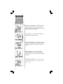
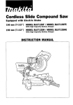
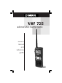
VHF 725 submersible marine radio owner’s manual and reference guide © 1999 GARMIN Corporation GARMIN International, Inc. 1200 E 151st Street, Olathe, Kansas 66062 USA Tel. 913-397-8200 or 800-800-1020 Fax. 913-397-8282 GARMIN (Europe) Ltd. Unit 5, The Quadrangle, Abbey Park Industrial Estate, Romsey, SO51 9AQ UK Tel. 011-44-1794-519944 Fax. 011-44-1794-519222 GARMIN (Asia) Corp. 3F, No. 1, Lane 45 Pao Hsing Road, Hsin Tien, Taipei, Taiwan, R.O.C. Tel. 011-886-02-2917-4107 Fax. 011-886-02-2917-1758 All rights reserved. Except as expressly provided herein, no part of this manual may be reproduced, copied, transmitted, disseminated, downloaded or stored in any storage medium, for any purpose without prior written consent of GARMIN Corporation. GARMIN Corporation hereby grants permission to download a single copy of this manual onto a hard drive or other electronic storage medium to be viewed for personal use, provided that such electronic or printed copy of this manual contains the complete text of this copyright notice and provided further that any unauthorized commercial distribution of this manual is strictly prohibited. Information in this manual is subject to change without notice. GARMIN reserves the right to change or improve its products and to make changes in the content without obligation to notify any person or organization of such changes. Visit the GARMIN website for current updates and supplemental information concerning the use and operation of this and other GARMIN products. Website address: www.garmin.com GARMIN and VHF 725 are registered trademarks of GARMIN Corporation and may not be used without the express permission of GARMIN. Part Number 190-00179-00 Rev. A Printed in Taiwan INTRODUCTION About This Manual Thank you for choosing the GARMIN VHF 725. To get the most from your new VHF marine radio, take time to read through this owner’s manual in order to understand all of the operating features. This manual is organized into three sections for your convenience: The Introduction to the VHF 725 Features section gives you an overview of the unit’s functional features. The Getting Started section gets you started on un using the VHF 725 for basic radio uses. The Reference section contains information on items such as accessories, a channel list, a trouble-shooting guide, and the index. Before getting started, check to be certain that your VHF 725 package includes the following items. If you are missing anything, please contact your dealer immediately. Standard Package: o VHF 725 Unit oOwner’s Manual o Lanyard oAntenna (SMA o Belt Clip Connector) o NiCad Battery Pack oCharging Unit o Charging Stand/Mounting Bracket Refer to Section 3, Appendix A, for a list of optional accessories available from your GARMIN Dealer. i INTRODUCTION FCC Compliance Statement FCC COMPLIANCE STATEMENT This device meets requirements for Parts 2, 15, and 80 of the FCC Regulations. It has been tested for compliance with all necessary FCC standards. This device complies with part 15 of the FCC Rules. Operation is subject to the following two conditions: (1) This device may not cause harmful interference, and (2) this device must accept any interference received, including interference that may cause undesired operation. The VHF 725 does not contain any user-serviceable parts. Repairs should only be made by and authorized service center. Unauthorized repairs or modifications could void your warranty and your authority to operate this device. IMPORTANT! GARMIN strongly recommends obtaining a marine radio user’s guide such as the “Maritime Radio User’s Handbook” published by the RCTM (Radio Technical Commission for Maritime Services), P.O. Box 19087, Washington, D.C. 20036, to ensure proper radio operation and protocol. Improper usage can result in fines levied on mariners by the FCC. ii INTRODUCTION Warnings and Precautions IMPORTANT! The Telecommunications Act of 1996, effective February 8, 1996, provides the FCC discretion to eliminate radio station license requirements for aircraft and ships. At the present time, you do not need an individual license to operate the VHF 725 aboard your private vessel in many circumstances. To find out the specific details on whether you are exempt from licensing, please refer to the FCC Fact Sheet PR 5000 or contact the FCC at: 1-800-322-1117. Note that no license is required for a portable radio used only as a backup on a vessel which already has a station license per FCC 506 Instructions, dated 1993. If a marine license is required or desired, contact the FCC at 1-800-322-1117 to request Form 506, Application for Ship Radio License. The FCC also has a fax-on-demand service to provide forms by fax at 1-202-418-0177. The VHF 725 user accepts all responsibility for obtaining the proper licensing before using the transmitter. WARNING! This transmitter will operate on frequencies (channels) that have restricted use in the United States. The channel assignments include frequencies assigned for exclusive use of the U.S. Coast Guard, use in Canada, and use in International waters. Operation on these frequencies without proper authorization is strictly forbidden. For frequencies (channels) that are currently for use in the U.S. without an individual license, please contact the FCC Call Center at 1-888-CALL-FCC. iii INTRODUCTION Warnings and Precautions IMPORTANT! Read all instructions carefully and completely before using the VHF 725 Marine Radio. This device is intended only as an aid to boating safety and navigation. The performance of the VHF 725 can be affected by many factors including environmental conditions and improper handling or use. It is the user’s responsibility to exercise good safety and navigational judgement and the GARMIN VHF 725 should not be relied upon in lieu of such prudence and judgement. CAUTIONS For these reasons, the operator should exercise the following precautions to ensure proper and reliable use of the GARMIN VHF 725. DO NOT operate this transceiver within 1 meter of the ship’s navigational compass. DO NOT recharge batteries except in methods described in this manual. DO NOT use this transceiver for inappropriate communications. Know and observe the FCC Rules for Marine Radio Operation. iv GETTING STARTED Table of Contents SECTION ONE Introduction Packing List....................................................................i FCC Compliance Statement...................................................ii Cautions.....................................................................iii-iv SECTION TWO Getting Started Unit Description...............................................................2-3 Keys and Function Displays............................................4-9 Maritaime Radio Services Operation............................10-14 Installing the Antenna.........................................................15 Installing the Battery pack..............................................15-16 Selecting a Channel.......................................................16-17 Setting the Squelch Threshold..............................................17 Adjusting the Volume...........................................................18 Scanning Channels..........................................................18-19 Tri-Watch........................................................................19-20 Monitoring Weather Channels.......................................20-21 Receiving and Transmitting...........................................21-24 Backlighting the LCD Display & Keypad..............................24 Using the Key Lock Feature..................................................24 SECTION THREE Appendix A Appendix B Appendix C Appendix D Appendix E Appendix F Appendix G Apprendix H - Reference Optional Accessories............................25-26 Specifications...........................................27 VHF Channel List.............................28-29 Maintenance and Troubleshooting........30-32 Messages...................................................33 Glossary.....................................................34 Index.........................................................35 Warranty and Service Information................36 1 GETTING STARTED Unit Description Flexible Antenna Squelch Key LCD Display Screen Press To Talk (PTT) Key Hi/Low Power and Key Lock Key Scan Key Memory Key Channel Band Selection Key Tri-Watch Channel 16- Channel 9 Key Power/Backlighting Key Weather/Regular Channel Weather Alert Key Battery Pack +/- Volume Control Keys UP/DOWN Arrow Channel Selection Keys Microphone Speaker 2 GETTING STARTED Unit Description The VHF 725 is a 5 watt marine VHF communications transceiver in a convenient handheld package. A keypad located on the front of the unit provides onehand control of communication features. The knobless design allows push-button Squelch and Volume adjustment. A single button press provides a manual Squelch Override function. Tri-Watch monitoring mode allows simultaneous monitoring of emergency channel (16), calling channel (9) and a channel selected by the user. The channel 16/9 key allows you to toggle between emergency and calling channels. A 1” high by 1-3/8” wide LCD display provides indication of all features and functions of the VHF 725. The scan feature allows the operator to select up to 10 channels for continuous monitoring in any combination of U.S.A., Canadian, and International bands. The weather channel key toggles between regular channels and weather channels. It enables the weather alert mode when pressed and held for more than one second. The high/low key toggles the transmitter power level from between five watts and one watt. When held for more than one second, it locks and unlocks the “Key Lock” function to prevent inadvertent changing of unit settings and modes. The power key turns the unit off and on and, when pressed briefly after the unit is powered on, enables the display backlighting feature and illuminates the keys on the front of the unit. The weather/regular channel key enables or disables the weather alert function. Small size and light weight characterize the portability of the GARMIN VHF 725. 3 GETTING STARTED Keys & Function Displays Power/Backlighting Key Channel Up & Channel Down Keys Weather Channel/ Regular Channel Key Eleven keys provide access to all of the unit’s features and functions. When any key (except the PTT key) is pressed, the unit will acknowledge by emitting a single beep confirmation tone. Some keys have dual functions and those keys on the front of the unit are illuminated when the display backlighting feature is active. Power/Backlighting Key - This key turns on the unit when pressed and released, and turns the unit off when pressed and held for more than one second. Briefly pressing and releasing the power key when the unit is on will activate the backlighting feature and will last for five seconds after the last key is pressed. Channel Up and Channel Down Keys Pressing these CH arrow keys sets the operating channel. Pressing these keys while the Squelch key is pressed and held, sets the squelch threshold level. Weather Channel/Regular Channel Key Pressing and releasing this key will toggle between the ten weather channel band and the fifty-six regular channel band. Pressing this key for more than one second will activate the weather alert feature if a weather channel is currently displayed. NOTE: WX Alert Mode will interrupt regular use momentarily to monitor for a weather alert tone on the selected weather channel. Volume Increase & Volume Decrease Keys 4 Volume Increase and Volume Decrease Keys Pressing the plus and minus keys increases or decreases the volume of received transmissions and audio tones. GETTING STARTED Keys & Function Displays Memory Key - Pressing this key after selecting a channel places that channel into the scanning memory. Pressing this key when a channel is stored in memory (as indicated by the MEM icon on the display) will remove the channel from memory. A maximum of ten channels can be stored in memory. Scan Key - Pressing this key starts the scanning of channels entered into memory. Pressing this key while scanning disables the scan feature while retaining the selected channels in memory. U/I/C (USA, International/Canadian) Frequency Bands Key - This key allows the operator to select from the three channel bands. Pressing and releasing the key sequences through the three bands. The band selected is displayed on the LCD screen. Channel 16/9 and Tri-Watch Key - This key provides the operator with a choice of three channel monitoring options. Pressing once will monitor channel 16 (the emergency channel). Pressing again will monitor channel 9 (the calling or hailing channel). Pressing a third time will return to the last used regular channel. Pressing and holding for more than one second will activate Tri-Watch to continuously monitor channels 16, 9 and a channel of your choice, from the regular or weather band. PTT (Press To Talk) Key - This Key allows the operator to transmit over those regular band channels that permit transmission. Press and hold the key to talk and release to receive. Memory Key Scan Key USA INT CAN U/I/C Frequency Bands Key Channel 16/9 & TriWatch Key PTT PTT Key 5 GETTING STARTED Keys & Function Displays Squelch Key H/L Power Key 6 Squelch Key - This key breaks the squelch (unmutes the audio) when pressed and held. It is also used to set the squelch threshold (the level at which only strong signals can be received). The squelch threshold is set by pressing and holding the squelch key while using the UP/ DOWN keys to adjust the squelch level from 0 to 9. At level 0 (L0), all signals can be heard, while at level 9 (L9), only the strongest signals can be heard. Adjusting the squelch level eliminates weak, unwanted signals, as explained on page 17. H/L (High/Low) Power Key - This key toggles the transmitter power level from High (5 watts) to Low (1 watt) when pressed and released. It also locks the keypad when pressed and held for more than one second. The Power key, PTT key, backlighting key and the Squelch key still function in the Lock mode. Locking the keypad prevents inadvertent changing of channel settings and feature modes. GETTING STARTED The VHF 725 LCD Display Screen gives indication of channels being monitored, battery power level, volume level, and the status of all unit features. Keys & Function Displays Channel Number Indicator - This large numeral display indicates the selected operating channel or the squelch threshold setting when the squelch key is pressed. This indicator is always active. Channel Number Indicator Channel Band Indicator - This display provides indication of the regular channel band selected, U.S.A., International, or Canadian. Channel Band Indicator Weather (WX) Channel Indicator - This display provides indication that a weather channel is currently being monitored. Weather Channel Indicator Memory Channel Indicator - This display, in conjunction with the Channel Number Indicator, indicates that the channel number displayed has been entered into the unit memory for selection when the scan feature is active. Memory Channel Indicator Tri-Watch Indicator - This display appears along with the Emergency (16) and Call (9) Channel indicators to give notification that the Tri-Watch (three channel monitoring) feature is active. Tri-Watch Indicator 7 GETTING STARTED Keys & Function Displays Weather Alert Indicator - This display gives indication that the weather alert function has been activated. The display will flash whenever a weather alert tone is received. Weather Alert Indicator Lock Indicator - This indicator is displayed when the Lock feature is active. Lock Indicator Battery Level Indicator - This battery shaped icon displays information about battery capacity in 25% increments. This indicator is always active. Battery Level Indicator Squelch Indicator - This display appears whenever the SQ, squelch key is presses for either squelch override or setting of the squelch threshold. Squelch Indicator Low Battery Indicator - This indicator flashes on and off when the battery capacity drops to 10% or below. Low Battery Indicator 8 GETTING STARTED Keys & Function Displays Volume Level Indicator - This band of gradually rising bars provides an indication of the volume setting. This indicator is always active. Volume Indicator Hi/Low Power Indicators - These displays indicate the transmitter power level. NOTE: Some channels only permit transmission on Low while others allow only receive operation. Hi/Low Power Indicator Scan Indicator - This display provides indication that the Scan feature is active. Scan Indicator Receive (RX) Indicator - This indicator provides notice that a signal is being received by the unit. Receive Indicator Transmit (TX) Indicator - This indicator appears when you are using the VHF 725 to transmit and will come on when you hold down the PTT key. Transmit Indicator 9 GETTING STARTED Maritime Radio Services Operation Important Information for First Time Users About Operating a Marine Radio If you are a first time user of a marine radio, you should be aware of methods for operating your GARMIN VHF 725. Although, as explained on page iii, a Federal Communication Commission (FCC) license is no longer required for individual operator use, you must comply with all applicable FCC rules and regulations. We recommend that you obtain a copy of the “Maritime Radio Users Handbook” an authoritative handbook prepared by the Radio Technical Commission for Maritime Services, Post Office Box 19087, Washington, D.C. 20036. In some instances, such as commercial vessels, operators are required to obtain a license. You can obtain a license application from your nearest FCC field office. It is your responsibility to determine if you are required to apply for a license. If you have questions about the use of your marine radio you can contact the FCC Call Center at 1-888-CALL-FCC. For safety and efficient navigation of vessels, the maritime radio frequency bands are separated into four groups. Specific frequencies within each are assigned for particular safety and functional applications, such as ship to shore communications, US Coast Guard use, and navigation in waterways and ports. You may not have access to some which are not-for-public-use frequencies, and you are required to monitor and use others which are safety and navigational procedure frequencies. 10 GETTING STARTED Maritime Radio Services Operation The four groups you will have occasion to use are the U.S.A. Regular Band of 52 channels, the Canadian Band of 56 channels, the International Band of 55 channels, and the Weather Band of 10 channels. Some of these are receive (listen) only, such as the weather channels. The emergency channel 16 is restricted to hailing of other vessels, distress calls and safety purposes only. Known as the Hail and Distress Channel, it is used to contact nearby vessels and in emergencies where there is threat to life or property. The calling or hailing channel 9 is used for establishing contact with another vessel as an alternate to channel 16. As channel 16 is often used so frequently that hailing vessels is not practical in some high traffic areas. Contact is made using channel 9 and then switched to another regular channel for exchange of information. Maritime radio users are required to monitor channel 16, it is also advisable to monitor channel 9 and a weather channel as well. To facilitate these requirements, the VHF 725 is equipped with Tri-Watch and Weather Alert features that allow you to engage in regular channel communications and monitor both the emergency channel and the alternate calling channel while also being alerted of severe weather conditions. Appendix C on pages 28 and 29 of this manual provides a listing of channels and the use of each, including those which are for receiving broadcast messages only. 11 GETTING STARTED Maritime Radio Services Operation Here is a grouping of the channels and a brief description of their use. Channels 5, 12, 14, 20, 65, 66, 73, 74, 77: Port Operations - Can be used by any vessel for communications between ships and ship-tocoast stations for messages relating to operational handling, movement and safety of vessels in or near ports, locks or waterways. Channel 77 is limited to communications to and from commercial pilots in regard to movement and docking of vessels. Channels 11,12, 13, and 14 are used for traffic service on the Great Lakes, St. Lawrence Seaway and designated major ports. Channel 6: Intership Safety - For use by any vessel for communicating navigational and weather warnings to other ships. Also used for communicating with the U.S. Coast Guard during search and rescue operations. Ship-to- ship communications only. Do not use for routine communications as this is a safety channel. Channels 7, 8, 9, 10, 11, 18, 19, 67, 79, 80, 88: Commercial Vessels - Used for communication between vessels pertaining to the purpose for which the vessel is used. Limited communications between vessels and coast stations. Recreational boats are not permitted to use these channels. Channels 8, 67, and 88 may not be used for ship-to-coast communications. Channel 88 is not available on the Great Lakes and St. Lawrence Seaway. Channels 9, 68, 69, 71, 72, 78: non-Commercial (Boat Operations) - Used by recreational boaters and others not engaged in commercial transport. Provides a communication channel pertaining to the needs of the vessel (maneuvers, berthing, provisioning, fueling, etc.). Used as a second receiver between ship-to-ship and ship-to-limited coast stations. Channel 72 may not be used for ship-to-coast communications and channel 9, the alternate calling channel, is shared with commercial vessels. 12 GETTING STARTED Maritime Radio Services Operation Channel 13: Navigation - used by any vessel for safety communications regarding the maneuvering of vessels or directing of a vessels movements. Ship-to-ship and secondarily ship-to-coast communications. Commonly called the Bridge-to-Bridge channel. For routine operations, radio power must be reduced to one watt. Channel 15: Environmental - Used by any vessel to receive only broadcast information concerning environmental conditions in which vessel operate, such as, weather, sea conditions, time signals, and hazards to navigation. One-way broadcast from coast-to-ship stations. Channel 16: Emergency - Used if your vessel is sinking or on fire, someone has been lost overboard, or there is grave and imminent danger to life or property. Every ship is obliged to give priority to radio distress communications. Calling - This channel is also used to establish communication with another marine radio station. After contact is made, switch to a working channel. Due to congestion on channel 16, particularly in high traffic areas, the FCC has approved channel 9 as a second hailing channel. Channel 17: State Control - Used by state and local government vessels to coordinate, regulate and control boating activities and the rendering of assistance. Channel 22: U.S. Coast Guard - For use by any vessel for exchange of communications with a U.S. Coast Guard station. Communication is ship-to-U.S. Coast Guard ship, and coast-to-aircraft station. Establish contact on channel 16 then shift to channel 22 as directed by the U.S. Coast Guard. 13 GETTING STARTED Maritime Radio Services Operation Channels 24, 25, 26, 27, 28, 84, 85, 86, 87: Marine Operator Can be used by any vessel to place a telephone call to any place in the world or to a vessel outside their transmitting range. Used between vessels and public coast stations. You must contact a marine operator on the channel assigned to your navigating area. Channels WX1, through WX10: Weather - Used by any vessel to receive continuous weather information from the National Oceanic and Atmospheric Administration (NOAA). This is a one-way broadcast to any interested parties. You are not allowed to transmit on these frequencies. A list of weather broadcast stations for the U.S. is contained in the “Maritime Radio Users Handbook”. They provide continuous around-the-clock broadcasts of the latest weather information directly from the national Weather Service Offices. These channels are designated on Marine VHF equipment as WX1 through WX10, but are rarely used beyond WX7. During severe weather, National Weather Service forecasters can interrupt routine weather broadcasts and substitute special warning messages. Specially designed warning receivers either sound an alarm indicating an emergency exits or tune into the weather frequency. The VHF 725 is equipped to sound the alarm tone and tune into the broadcast when the Weather Alert feature is activated. Some channels will appear on the display with an “A” suffix. Hese are “Simplex Channels” receiving and transmitting on the same frequency. See “Selecting a Channel” on page 16 for a more detailed explanation. There are other regular channels in the list of channels on pages 28 and 29 that are not defined above. They have special uses that do not apply generally to regular maritime traffic and communications. 14 GETTING STARTED Installing the Antenna The antenna is an essential part of your VHF 725 and the unit should never be operated without the antenna installed, as this may result in damage to the unit. The antenna receives signals best when held upright and is less effective when positioned horizontally. Antenna & Battery Installation To install the antenna: 1. Carefully align the bottom of the antenna with the threaded connector on the top of the VHF 725, and screw it on the until snug against the seating surface. (Figure 1) Antenna Installing the Battery Pack The VHF 725 uses a rechargeable NiCad Battery Pack to provide approximately 10 hours of operating time under normal use. Alkaline “AA” batteries installed in the optional GARMIN Battery Tray may also be used. The battery level indicator at the lower left corner of the unit LCD display gives indication of battery capacity in increments of 25%. The Battery Pack is provided with a Charging Stand and Charging Unit. FIGURE 1 Charging Unit To assemble the Charging Unit: 1. Insert the Charging Unit cord plug with contact pins into the base of the Charging Stand. Position the flange on the plug over the slots in the bottom of the stand base and then press down until it clicks into place. Pull the cord away from the stand slightly to allow the plug to move down freely. (Figure 2) 2. Connect the Charging Unit to a 120 VAC Power Outlet. 3. The NiCad Battery Pack should be installed in the VHF 725 when you remove it from the shipping carton. Place it base-down into the charging stand and allow 12 hours for charging to full capacity. Charging Stand Bend Cord Plug Detail of Charging Stand Base FIGURE 2 15 GETTING STARTED Selecting A Channel VHF 725 Unit Battery Pack D-Ring with Slot FIGURE 3 4. If you have an additional NiCad Battery Pack to use as a spare, you may insert it directly into the charging stand for recharging. 5. To remove a depleted Battery Pack and install a spare, lift up the D-Ring on the Battery Pack screw and use it or a coin inserted in the screw slot to turn the screw to remove the depleted Battery Pack from the unit. 6. After installing the spare Battery Pack, press the POWER key to be certain the battery has been properly charged and the unit is functioning. Observe the Battery Level indicator on the LCD display to be certain you have installed a fully charged Battery Pack. NOTE: If using two battery packs, with one as a spare, it is recommended to cycle both packs through the unit as NiCad batteries will selfdischarge when stored for long periods of time. This practice will ensure a fully charged spare battery at all times. Selecting a Channel Selected Channel Band Select Channel Select FIGURE 4 16 To begin using the VHF 725 you will want to select a channel to monitor while you personalize the unit settings, such as volume and squelch. When you power-up the unit, a channel will automatically be selected, but it may not be suitable for making unit settings. To select a channel: 1. Use the U/I/C Channel Band key to select USA, International, or Canadian channel bands. (Figure 4) The unit was set at the factory to channel 10 before shipment. 2. Press the UP or DOWN arrow key to scroll through the channels available on the selected band. (Figure 4) If you dont know which channel to select, refer to the Channel List in Appendix C on pages 28 and 29. NOTE: You will notice an A indicator adjacent to some channel numbers in the USA and Canadian bands. These are simplex channels (transmitting and receiving on the same frequency) while the International counterpart is a duplex channel (transmitting on one frequency while receiving on another.) GETTING STARTED Setting the Squelch Threshold Setting the Squelch Threshold Setting the Squelch is important for reception of signals you want to hear. There are ten threshold levels, from 0, which allows all signals to be received, to 9, which allows only the strongest signal to be heard through the speaker. The diagram in Figure 5 demonstrates how setting the threshold level allows you to hear only the signals you desire, while weaker, unintelligible signals are not heard. To set the Squelch threshold: 1. Adjust the Squelch to the lowest setting by pressing and holding the Squelch (SQ) key, then pressing the DOWN arrow key repeatedly until the display indicates L0. You should hear static. If you hear a voice transmission, change to another channel and repeat this step. (Figure 5) Signal At Level 6 5 4 Only Signals Sronger Than Level 5 Will Be Heard 3 2 1 EXAMPLE of THRESHOLD SET AT LEVEL 5 Selected Squelch Level 2. While holding the Squelch (SQ) key down, use the UP arrow key to increase the squelch level to L1. If no static is heard, you have set an acceptable squelch threshold level. If you hear static, then increase to the next threshold level, repeating the process until unwanted static is eliminated. Release the SQ key to return to your selected channel. The squelch setting is universal for all channels, but it may require resetting from time to time NOTE: During squelch adjustment, Tri-Watch, Scan, and Weather Alert are suspended. Up/Down Keys Squelch (SQ) Key FIGURE 5 17 GETTING STARTED Adjusting Adjusting the Volume The Volume key may be adjusted using the +/- keys. The volume level is indicated by the Volume, Scanning band of gradually rising bars on the LCD display. To adjust the volume: 1. Press the + key to increase the volume or the - key to decrease the volume. (Figure 6) Scanning Channels Volume Level Indicator Volume Decrease Increase FIGURE 6 To scan channels: Scanning Display Band Select Channel Select Memory Select Scanning Select FIGURE 7 18 You may want to keep in contact with several vessels in your immediate area at the same time. For this purpose, the scan feature is available. You can program up to ten channels from any combination of USA, International, or Canadian bands into memory. Whenever a transmission is received, the scan will stop at that channel until the transmission ends and then move on until it recognizes another transmission. You cannot scan weather channels since they broadcast continually and do not allow a break in transmission for the scan to move to the next channel. You can utilize the WX Alert feature to monitor for severe weather conditions. 1. Before activating the scan feature you must program at least two channels into memory. You can do this by pressing the U/I/C key to select the desired channel band and then use the UP/DOWN arrow keys to select channels in that band. Press the MEM key to place the displayed channel in the scan memory. (Figure 7) 2. Repeat this process for the desired channels. 3. Press the SCAN key to begin the scanning process. Pressing the SCAN key again will stop the scanning process. NOTE: If the PTT key is pressed during scanning (when the display is changing) it will cancel SCAN and stop at the channel last scanned. If a channel is static (being received) you must transmit within 5 seconds after the received broadcast ends before SCAN moves to the next channel. After transmitting, scanning resumes when you release the key. Pressing any other keys will cancel the scan with the exception of the Power, Volume +, Volume -, Squelch and Hi/Low keys. GETTING STARTED Tri-Watch 4. To remove a channel from the scan memory, simply access it with the UP/DOWN arrow keys and press the MEM key. NOTE: Channels entered into memory will be retained when the unit batteries are removed. Tri-Watch Tri-Watch is a method of monitoring the emergency channel 16 and the alternate hailing channel 9 while monitoring the channel you are using for communications. To use Tri-Watch: 1. First determine which channel other than 16 and 9 that you desire to monitor, then use the UP or DOWN arrow keys to make a choice. 2. Press and hold the TRI-16/9 key for more than one second. (Figure 8) 3. Observe the LCD display showing TRI-16-9, and the cycling set of channel numbers indicating that the TRI-WATCH feature is active. Tri-Watch Display TRI Press and Hold for More Than 1 Second FIGURE 8 4. Observe that when a transmission is received by the third channel, reception will be briefly interrupted to monitor channels 16 and 9. If reception is on channel 9 it will be interrupted to monitor channel 16. Channel 16 always has priority in TRIWATCH. 5. To cancel the TRI-WATCH feature, press the TRI16/9 key to monitor only channel 16 or any other key to return to a selected channel. 19 GETTING STARTED Monitoring Weather Channels NOTE: If you enter channel 16 into memory for the Scan Mode, it will not have the priority it receives in the Tri-Watch Mode. Monitoring Weather Channels There are ten weather channels which provide continual broadcasts of area weather information as provided by the National Weather Service. Typically, only the first seven channels are actively used. To monitor weather channels: 1. Press the WX/CH-ALERT key to toggle between regular channel and weather channel bands. The WX symbol on the display screen will appear when you have accessed the weather band. (Figure 9) Weather Channel & Weather Alert Display ALERT Select Weather or Regular Channels Activate Weather Alert Select Channel FIGURE 9 20 2. Use the UP/DOWN arrow keys to select the weather channel broadcast for the area you are navigating. NOTE: You can monitor channels to determine the area weather broadcast you desire to monitor or refer to the list of weather broadcast stations published in the Maritime Radio Users Handbook. Once you have selected a weather channel you can toggle back and forth to the regular channel bands by pressing the WX/CH ALERT key. Weather Alert The Weather Alert Feature can be activated to briefly monitor for a weather alert tone (every 5 seconds). You can choose a weather channel to monitor, activate the “WX Alert” feature then resume regular use of the radio. When a weather alert signal is detected the “WX ALERT” wording on the display will flash, and after an alert tone, the VHF 725 will automatically access the weather channel. It will increase the volume to mid-range, if set lower, and allow you to hear severe weather information. To activate Weather Alert: 1. Press and hold the WX/CH-ALERT key for more than one second to activate this mode. 2. Return to regular use of the radio. You will hear a Weather Service beep tone and observe the flashing WX Alert display when a weather alert signal had been detected followed by the severe weather alert broadcast. (Figure 9) 3. To cancel the Weather Alert feature, press and hold the WX/CH-ALERT key or turn the unit off. Receiving and Transmitting Whenever the VHF 725 is powered-up (On) it is in the receiving mode. If the unit is monitoring a channel that is broadcasting, you will hear that transmission. It is possible to monitor any channel on any band, but transmission on some channels is not allowed. Many are receive only channels, while others are simply not intended for your category of radio use. To receive on the VHF 725: 1. Press and release the PWR key to turn the unit on. 2. Observe that the display screen will come on and the last channel accessed will be displayed. If there is someone transmitting on that channel, you will hear their communication and the RX symbol will appear on the LCD display. You may now select from the many receiving options. GETTING STARTED Receiving and Transmitting Power Saving Tip! To monitor the weather alert feature and save battery power: 1. Select a weather channel. 2. Initiate Weather Alert. 3. Reduce volume to minimum. 4. Press and hold the LOCK key. The audio will mute and the VHF 725 will wake-up from a lower power mode to monitor for the weather alert tone every 5 seconds. Pressing any key that is functional during the LOCK mode will cancel the Low Power mode and switch to regular WX/Alert Mode. A weather alert tone from the National Weather Service will also cancel the Low Power mode and tune the receiver to the active weather alert channel at mid-volume level. NOTE: For clearer reception, you can adjust the volume key up or down and set the squelch threshold to a level at which the audio will be enabled. 21 GETTING STARTED Receiving and Transmitting 3. Press the WX/CH key to choose from weather channels or regular channels. (Figure 10) 4. Press the U/I/C key to select a channel band. (Figure 10) 5. Press the UP/DOWN arrow keys to select a channel. (Figure 10) Receiving Mode Display Toggle From Weather ALERT To Regular Channels Select Channel Band Select Channel Enter Channel Into Memory Activate SCAN Feature TRI Activate Emergecy Monitor or Tri-Watch Feature FIGURE 10 22 6. Press the MEM key when scrolling through the channels to enter up to ten channels in the SCAN memory. You must select at least two for the SCAN feature to activate. (Figure 10) 7. Press the SCAN key to monitor the selected channels. (Figure 10) 8. Press the 16/9 key once if you want to monitor the emergency channel (16). (Figure 10) 9. Press the 16/9 key twice if you want to monitor the alternate calling channel (9). 10. Press and hold the 16/9 key if you want to activate the TRI-WATCH feature in order to monitor the emergency, the alternate calling and one regular channel simultaneously. To transmit on the VHF 725: 1. Perform Steps 1 through 5 of the procedure for receivng, above. 2. Choose a correct channel for communications. Channels are restricted to use by various goverment agencies, types of vessels and maritime service operators. Review the list in Appendix C to determine which channels are available for your use. GETTING STARTED 3. Wait until the channel you have selected is free of communications. THIS IS AN FCC REQUIREMENT! NOTE: For communications over short distances, press the H/L key until LOW is displayed on the LCD. This reduces transmission power to one watt, prolonging battery life. Receiving and Transmitting TX 4. Press and hold the PTT (Press To Talk) key and begin your transmission. The TX symbol will appear on the LCD display. (Figure 11) 5. Speak directly into the microphone on the front of the unit (see page 2) and hold the unit vertically 1 to 2 inches from your mouth. NOTE: VHF Marine Radios communicate over distance by Line-of-Sight, which means that the signal may be blocked by objects such as land forms, large vessels, etc. It is therefore important to transmit with the antenna in a vertical position and with the radio positioned as far above the water as is feasible. Transmit Display PTT Press and Hold While Transmitting FIGURE 11 6. Release the PTT key when you have completed your transmission. NOTE: You must use a specific communication style when using a marine radio, such as your station call sign or boat name and ending your transmission with proper terminology such as Over. Refer to the Maritime Radio Users Handbook. Also be aware that the unit will automatically cancel TX after the PTT key has been pressed for more than thirty seconds to limit extensive transmissions and protect the unit from damage. 23 GETTING STARTED Backlighting & Key lock Features The FCC prohibits the following communications: o False distress or emergency messages oMessages to Any Boat except in emergencies and radio tests oMessages to or from a vessel on land and transmission while on land oObscene, indecent, or profane language (potential fine of $10,000) 7. Remember to return to monitoring of Channel 16 by pressing the 16/9 key once when not using another channel. Backlighting the LCD Display & Keypad The backlighting feature is used to improve readability of the LCD display and keypad in dim light. 1. Press and release the PWR key after the unit has powered on. The display will be illuminated for 5 seconds after the last key press before cycling off. NOTE: Press this key anytime you require visual reference in dim light. Using the Key Lock Feature Key Lock Display H L Press and Hold for More Than 1 Second FIGURE 12 If you desire to maintain a selected function on your VHF 725, such as TRI-WATCH, SCAN, or Weather Alert, you can lock the keys using the Lock feature to prevent inadvertent canceling or changing of unit settings. However, the PressTo-Talk, Squelch, and Power keys still function. 1. Press the H/L-LOCK (Hi/Low transmission power) key for more than one second after you have set the unit to the function desired. When the unit keypad is locked, the LOCK message will be displayed on the LCD screen. (Figure 12) 2. To cancel the lock feature, press the H/L-LOCK key again for more than one second or turn off the unit using the POWER key. 24 APPENDIX A Accessories & Installation Standard Accessories & Replacement Components (Included with the VHF 725) Antenna......................................... Part Number: 700-00010-00 NiCad Battery Pack Kit (Includes Battery Pack and Charger & Charging Stand.) ...................................................... Part Number: 010-10188-00 Alkaline Battery Tray (Requires Six “AA” Alkaline Cells)................................. ........................................................ Part Number: 010-10214-00 Wrist Strap....................................... Part Number: 013-00027-00 Belt Clip........................................... Part Number: 145-00327-00 Belt Clip Mounting Screws............... Part Number: 211-54307-11 Cigarette Lighter Charging Cable Assy.................................................. ..........................................................Part Number: 010-10190-00 Owner’s Manual............................. Part Number: 190-00179-00 Contact GARMIN Customer Service to obtain replacement parts. Refer to Page 15 for Antenna and Battery Pack Installation. Cigarette Lighter Charging Cable Assembly Alkaline Battery Tray Charges the battery pack using a 12 volt power source. Provides an alternate source of power. Installing the Belt Clip and Wrist Strap The VHF 725 is supplied with a belt clip and carrying strap so you can carry the unit wherever you go. Attach the clip to the back of the unit using the two mounting screws provided. To attach the wrist strap, thread the cord portion of the strap through the slot in the clip then insert the solid end of the strap through the loop formed by the cord, pulling it through until snug. (Figure 13) Wrist Strap Mounting Screws Back of VHF 725 Slot for Wrist Strap Belt Clip FIGURE 13 25 APPENDIX A Optional Accessories Optional Accessories Nickel Metal Hydride Rechargeable Battery Pack.(50% more capacity than the NiCad Pack)..........................................Part Number: 010-10245-00 Spare NiCad Battery Pack.......................Part Number: 010-10189-00 VHF 725 Soft Carry Holster................... Part Number: 010-10219-00 Contact your GARMIN Dealer to obtain these optional accessories. VHF 725 Optional Accessories: Nickel Metal Hydride Battery Pack Soft Carry Holster Provides 50% more battery capacity. Recharges using the charging stand and charging unit provided with the VHF 725. Rugged nylon holster with integral belt loop. Spare NiCad Battery Pack Allows for uninterrupted use of the VHF 725. Use while charging the original battery pack. 26 APPENDIX B Specifications Physical: Size: 5.5”H x 2.0”W x 1.3”D (14.0 x 5.0 x3.3cm) Weight: Approximately 12.1 oz (.35Kg) Temperature Range: -4 to +158 degrees F (-20 to + 70 degrees C) Transceiver: Frequency Bands: All U.S., Canadian, and International marine channels plus 10 weather channels Channel Spacing: 25 kHz Selectivity: Adjacent channel selectivity, 70 dB Intermodulation rejection, 68 dB Spurious Image Response, 70 dB Sensitivity (FM): (WX): > 12 dB SINAD at 0.3 microvolt > 12 dB SINAD at 0.3 microvolt Squelch Sensitivity: (Threshold) -123 dBm to -107 dBm Audio Power: 0.5 W into 16 ohm speaker Audio Distortion: < 10% Hum and Noise: < 40 dB Transmitter Output: 5 watts high/1 watt low Frequency Stability: +/- 10 PPM Hum and Noise: < 40 dB Spurious Emissions: < 70 dB Duty Cycle: No damage, even if continuously keyed Microphone: Internal, electret Compliance: FCC Part 87 Operating Voltage: 7.5 VDC Receiver: Transmitter: Power: Source: Standard Optional Battery Life:* NiCad rechargeable battery pack (6) “AA” alkaline battery cells 10 hours with NiCad Battery Pack 6 hours with 6 “AA” alkaline cells 13 hours with NiMH Battery Pack Current Consumption: Receiver: < 50 mA Transmit: High Power <1.6 A - Low Power <0.8 A * Tested using 5% TX (High), 5% RX, 90% Standby Duty Cycle 27 APPENDIX C VHF Channel List Channel Number Frequency (MHz) USA CAN INT TX RX 01 01 156.050 160.650 01A 156.050 156.050 02 02 156.100 160.700 03 03 156.150 160.750 03A 156.150 156.150 04 156.200 160.800 04A 156.200 156.200 05 156.250 160.850 05A 05A 156.250 156.250 06 06 06 156.300 156.300 07 156.350 160.950 07A 07A 156.350 156.350 08 08 08 156.400 156.400 09 09 09 156.450 156.450 10 10 10 156.500 156.500 11 11 11 156.550 156.550 12 12 12 156.600 156.600 13 156.600 156.600 13 13 156.650 156.650 14 14 14 156.700 156.700 15 NO TX 156.750 15 15 156.700 156.700 16 16 16 156.800 156.800 17 17 17 156.850 156.850 18 156.900 161.500 18A 18A 156.900 156.900 19 156.950 161.550 19A 19A 156.950 156.950 20 20 157.000 161.600 20 157.200 161.650 21 157.050 161.650 21A 21A 157.050 157.050 22 157.100 161.700 22A 22A 157.100 157.100 23 23 157.150 161.750 23A 157.150 157.150 24 24 24 157.200 161.800 25 25 25 157.250 161.850 26 26 26 157.300 161.900 27 27 27 157.350 161.950 28 28 28 157.400 162.000 60 60 156.025 160.625 61 156.075 160.675 61A 61A 156.075 156.075 62 156.125 160.725 62A 156.125 156.125 28 Type of Traffic Com’l, Port Ops, VTS Com’l, Port Ops, VTS Port Ops Com’l, Port Ops, VTS Com’l, Port Ops, VTS Port Ops Port Ops Port Ops, VTS Port Ops, VTS Safety Com’l Com’l Com’l Com’l & Non-Com’l Com’l Com’l, VTS, SMS Port Ops, VTS, SMS Navigational Navigational Port Ops Environmental Environmental Distress, Safety, Calling State Control Com’l Com’l Com’l Com’l Port Ops Port Ops U.S. Govt. Only U.S. Govt. Only Coast Guard Coast Guard U.S. Govt. Only U.S. Govt. Only Public Corresp. Public Corresp. Public Corresp. Public Corresp. Public Corresp - Function Ship to Ship Ship to Shore Yes Yes Yes Yes Yes Yes Yes Yes Yes Yes Yes Yes Yes Yes Yes Yes Yes Yes Yes No Yes Yes Yes Yes Yes No Yes Yes Yes Yes Yes Yes Yes Yes 1 watt, int. No Yes No Yes Yes RX Only 1 watt Only Yes Yes 1 watt Only Yes Yes Yes Yes Yes Yes Yes Yes Yes Yes Yes 1 watt Only Yes Yes Yes Yes Yes Yes Yes Yes Yes Yes Yes Yes Yes No Yes No Yes No Yes No Yes No Yes - APPENDIX C VHF Channel List Channel Number USA CAN INT 63 63A 64 64 64A 64A 65 65A 65A 66 66A 66A 67 67 67 68 68 68 69 69 69 70 70 70 71 71 71 72 72 72 73 73 73 74 74 74 77 77 77 78 78A 78A 79 79A 79A 80 80A 80A 81 81A 81A 82 82A 82A 83 83 83A 83A 84 84 84 85 85 85 86 86 86 87 87 87 88 88 88 88A Frequency (MHz) Type of Traffic TX RX 156.175 160.775 156.175 156.175 156.225 160.825 156.225 156.225 156.275 160.875 Port Ops. 156.275 156.325 Port Ops. 156.325 160.925 Port Ops. 156.325 156.325 Port Ops. 156.325 156.325 Port Ops. 156.375 156.375 Com’l. 156.425 156.425 Non Com’l 156.475 156.475 Non Com’l NO TX 156.525 Digital Selective Calling 156.575 156.575 Non Com’l 156.625 156.625 Non Com’l 156.675 156.675 Port Ops. 156.725 156.725 Port Ops. 156.875 156.875 Port Ops. 156.875 156.875 Port Ops. 156.925 161.525 Non Com’l 156.925 156.925 Non Com’l 156.975 161.575 Com’l 156.975 156.975 Com’l 157.025 161.625 Com’l 157.025 157.025 Com’l 157.075 161.675 U.S. Govt. Only 157.075 157.075 U.S. Govt. Only 157.125 161.725 U.S. Govt. Only 157.125 157.125 U.S. Govt. Only 157.175 161.775 U.S. Govt. Only 157.175 157.175 U.S. Govt. Only 157.225 161.825 Public Corresp. 157.275 161.875 Public Corresp. 157.325 161.925 Public Corresp. 157.375 161.975 Public Corresp. 157.425 162.025 Public Corresp. 157.425 157.425 Public Corresp. Weather Channels - Receive Only WX1 162.550 WX2 162.400 WX3 162.475 WX4 162.425 WX5 162.450 WX6 162.500 WX7 162.525 WX8 161.650 WX9 161.850 WX10 162.000 Weather Weather Weather Weather Weather Weather Weather Weather Weather Weather Function Ship to Ship Ship to Shore No Yes No Yes Yes Yes Yes Yes 1 watt Only Yes Yes No Yes Yes Yes Yes Yes No Yes Yes Yes No Yes Yes Yes Yes 1 watt int. Yes Yes Yes Yes Yes Yes Yes Yes Yes Yes Yes Yes Yes Yes Yes Yes Yes Yes Yes Yes Yes Yes Yes Yes Yes Yes Yes No Yes No Yes No Yes No Yes No Yes No Yes No No No No No No No No No No Yes Yes Yes Yes Yes Yes Yes Yes Yes Yes 29 APPENDIX D Maintenance & Troubleshooting Storage: Store the VHF 725 in a cool, dry location when not used for prolonged periods. When stored for more than six months, remove alkaline batteries to prevent leakage from expended cells. While the GARMIN VHF 725 is designed to withstand immersion in water (with or without the battery pack in place) it should be treated like all quality electronic equipment. Wipe away any water accumulation from the surface of the unit and use a paper towel or other absorbent material to wick out any moisture from the battery cavity. Exposure of battery terminals to salt spray may cause corrosion and loss of conductivity. Be certain to keep contacts dry and away from corrosive elements. Storage temperature should not vary from: below -4 degrees F (-20 degrees C) and above 158 degrees F (70 degrees C) Cleaning: Clean exterior portions of the VHF 725 with a mild soap and water solution. Do not use harsh detergents or solvent based cleaning agents. Isopropyl alcohol is acceptable. Wipe dry with a clean, nonabrasive cloth. Submersion in Water: The VHF 725 is constructed to meet IEC Standard 529 IPX7. It can withstand submersion in 1 meter of water for up to 30 minutes. Note that, while the unit is designed to operate after submersion, meaning; if dropped in water and retrieved quickly, it should suffer no damage. Prolonged submersion may cause damage to the unit. After submersion, be certain to remove the battery pack and dry the battery contacts and the battery cavity, as the battery cavity is separated from the rest of the unit and can allow water intrusion. Battery Maintenance: Keep battery contacts clean. Use only the NiCad Battery Pack or types of batteries specified for use with VHF 725. The VHF 725 accepts six (6) standard “AA” alkaline, rechargeable alkaline or rechargeable NiCad cells when the optional battery tray is used. It is advisable to maintain a supply of replacement batteries if the VHF 725 is to be placed in service for a prolonged period where recharging of the NiCad Battery Pack is not possible and replacement batteries cannot be easily obtained. NOTE: 30 Whenever possible, transmit with 1 watt power to prolong battery life. APPENDIX D Maintenance & Troubleshooting When Using The NiCad or NiMH Battery Pack*: Fully charge the battery pack before its first use. The battery pack requires 12 hours for a full charge and should not be charged in excess of this time period.. Charge only with the VHF 725 Charging Unit provided with the NiCad Battery Pack. Partially discharging a nickel-cadmium battery and then recharging it causes a phenomenon referred to as “memory reset”. When a battery that is not fully discharged is then recharged, it resets the memory in proportion to the amount of previous discharge, resulting in a gradually decreasing recharge capacity. To ensure that this type of battery pack retains its full capacity, it should be almost fully discharged (when the battery symbol blinks) and then recharged completely after every few cycles of use. * Municipal Law requires for environmentally sound collection and recycling or disposal of nickelcadmium batteries. Contact your local waste management official for instructions on disposal. Service and Repairs: The GARMIN VHF 725 is warranted for three years under the terms of the GARMIN Limited Warranty on Page 36 of this manual. If you need to obtain warranty service for your unit, call the GARMIN Product Support Department (913-397-8200) for a returned merchandise tracking number. The unit should be securely packaged with the tracking number clearly marked on the outside of the package and sent freight prepaid and insured to GARMIN warranty service station. A copy of the original sales receipt is required as proof of purchase for warranty repairs. GARMIN reserves the exclusive right to repair or replace the unit or software at its sole discretion. If your unit is no longer under warranty, GARMIN will make repairs at the GARMIN current labor rate and parts costs. Units repaired in this manner are warranted for 90 days from the date of return to the owner. 31 APPENDIX D Maintenance & Troubleshooting Troubleshooting Guide SYMPTOM PROBABLE CAUSE REMEDY Unit does not come ON Batteries are exhausted. Recharge batteries No sound from speaker Squelch threshold level too high. Set to a lower threshold point. No channel broadcast is being received Move to another channel. Volume is set too low. Increase volume. Some channels are for receive only. Change channel. Batteries are exhausted. Replace batteries. Some channels are for low power only. Change channels. Output power too low. Press H/L key for high power. The displayed channel cannot be changed. The LOCK function is on. Press an hold the H/L key for at least one second. Error tone (2 beeps) is heard when a key is pressed and no unit functoinis performed. Incorrect key selection and the programming is limiting key function. Select correct key. Cannot transmit or transmission isn’t being received. 32 APPENDIX E Messages Messages The VHF 725 responds to operating conditions in two ways, LCD Display screen messages and audio tones. These messages provide notification of errors in operation or the status of VHF 725 features. Audio Messages Confirmation Tones - These tones, consisting of a single “Beep”, are audible whenever you press a key on the unit and confirm that unit is responding to your action. Error Tones - These tones, consisting of two beeps and in some instances a continuous string of beeps, and indicate that you have pressed a key that cannot perform a function under the current unit operating mode. Screen Messages “LOW BATT” - This display appears when the battery capacity has dropped to 10% of its capacity. The “LOW BATT” display flashes and an initial three beep tone will be heard. The unit will operate under normal use for approximately 30 more minutes. “WX ALERT” - When the Weather Alert feature is activated by a weather alert broadcast, the weather alert tone will be heard and the “WX ALERT” display will flash. The receiver will be tuned to the weather channel and audio will be unmuted at the user setting or mid range volume level, whichever is greater. “TX” and “RX” - If these two icons flash together or the “TX” only flashes whenever the PTT key is pressed, the unit must be serviced. Contact the GARMIN Product Support Department at (1-800-800-1020) or (913-397-8200) for information. 33 APPENDIX F Glossary Glossary of Radio Terminology and Abbreviations Canadian Channels: Channel designations as defined by the International Telecommunications Service, (ITS). Duplex: Transmit and receive on different frequencies. FM: Frequency Modulation International Channels: Channel designations as defined for use in international waters by the ITS. PTT: Press-To-Talk switch RF: Radio Frequency RX: Receive Simplex: Transmit and receive on the same frequency. Squelch: To suppress background noise. Tri-Watch: Monitors Channels 16 and 9 while working on yet another user designated channel. TX: Transmit U.S.A. Channels: Channel designations as defined by the FCC. VHF: Very High Frequency (30 MHz to 300 MHz) Weather Channels: Channel designations as defined by the FCC. 34 APPENDIX G Index A Accessories............................25 Antenna Installation..............15 B Backlighting..........................24 Battery Installation................15 Battery Pack....................15, 26 Belt Clip................................25 C Calling Channel....................13 Cautions............................iv, v Channel Definition..........12-14 Channel List....................28-29 Cleaning...............................30 D Dual Watch..........................20 E Emergency Channel..............13 Error Tones...........................32 F FCC.................................iii - iv Flexible Antenna.....................2 K Keys and Displays..............4 - 9 Key Lock...............................24 M Maritime Radio User’s Hndbk....iii Marine Radio License.............iv Memory........................5, 7, 18 Messages...............................33 Monitoring......................18-20 N National Weather Service............14 NiCad Battery Kit........................26 P Packing List..................................ii Priority Scan...............................19 S Scanning Setup...........................18 Selecting Channel 16/9.........19, 22 Selecting a Channel.....................16 Selecting a Weather Channel.....20, 2 9 Specifications..............................27 T Transmitting...............................22 Tri-Watch...................................19 Trickle Charger...........................26 Troubleshooting..........................32 V VHF Communication..................10 VHF Line-of-Sight........................23 Volume Adjustment.....................18 W Warranty....................................36 Warranty Service..................31, 36 Weather Alert.............................21 Weather Channels................14, 29 35 APPENDIX H Warranty LIMITED WARRANTY GARMIN Corporation warrants this product to be free from defects in materials and manufacture for three years from the date of purchase. GARMIN will, at its sole option, repair or replace any components that fail in normal use. Such repairs or replacement will be made at no charge to the customer for parts or labor. The customer is, however, responsible for any transportation costs. This warranty does not cover failures due to abuse, misuse, accident or unauthorized alteration or repairs. THE WARRANTIES AND REMEDIES CONTAINED HEREIN ARE EXCLUSIVE AND IN LIEU OF ALL OTHER WARRANTIES EXPRESS OR IMPLIED OR STATUTORY, INCLUDING ANY LIABILITY ARISING UNDER ANY WARRANTY OF MERCHANTABILITY OR FITNESS FOR A PARTICULAR PURPOSE, STATUTORY OR OTHERWISE. THIS WARRANTY GIVES YOU SPECIFIC LEGAL RIGHTS, WHICH MAY VARY FROM STATE TO STATE. IN NO EVENT SHALL GARMIN BE LIABLE FOR ANY INCIDENTAL, SPECIAL, INDIRECT OR CONSEQUENTIAL DAMAGES, WHETHER RESULTING FROM THE USE, MISUSE, OR INABILITY TO USE THIS PRODUCT OR FROM DEFECTS IN THE PRODUCT. SOME STATES DO NOT ALLOW THE EXCLUSION OF INCIDENTAL OR CONSEQUENTIAL DAMAGES, SO THE ABOVE LIMITATIONS MAY NOT APPLY TO YOU. To obtain warranty service, call the GARMIN Customer Service department (913-397-8200) for a returned merchandise tracking number. The unit should be securely packaged with the tracking number clearly marked on the outside of the package and sent freight prepaid and insured to a GARMIN warranty service station. A copy of the original sales receipt is required as the proof of purchase for warranty repairs. GARMIN retains the exclusive right to repair or replace the unit or software or offer a full refund of the purchase price at its sole discretion. SUCH REMEDY SHALL BE YOUR SOLE AND EXCLUSIVE REMEDY FOR ANY BREACH OF WARRANTY. 36 © 1999 GARMIN Corporation GARMIN International, Inc. 1200 E 151st Street, Olathe, KS 66062 USA GARMIN (Europe) LTD., Unit 5, The Quadrangle, Abbey Park Industrial Estate, Romsey, SO51, 9AQ UK GARMIN (Asia) Corp., 3F, No. 1, Lane 45, Pao Hsing Road, Hsin Tien, Taipei, Taiwan R.O.C. Website address: www.garmin.com Part Number 190-00179-00 Rev. A