1
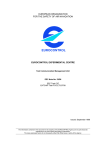
Rev 1 2 Section All Title LOG OF REVISIONS Description FAA Approval Complete Supplement Not FAA Approved Added FAA approval See Page 1 AFMS, TBM 700/850 G600 RVSM FAA APPROVED 190-00601-34 Rev. 2 Page 2 of 15 TABLE OF CONTENTS SECTION 1. GENERAL ................................................................................... 4 1.1 1.2 1.3 1.4 APPLICABILITY ..................................................................................... 4 RVSM GROUP AIRWORTHINESS APPROVAL ........................................ 4 DESCRIPTION ........................................................................................ 4 DEFINITIONS ......................................................................................... 6 SECTION 2. LIMITATIONS ........................................................................... 7 2.1 2.2 2.3 STATIC PORTS....................................................................................... 7 ADC 1-2 SWITCH ................................................................................. 7 REQUIRED EQUIPMENT ......................................................................... 7 SECTION 3. EMERGENCY PROCEDURES ................................................ 8 3.1 3.2 EMERGENCY PROCEDURES ................................................................... 8 ABNORMAL PROCEDURES................................................................... 12 SECTION 4. NORMAL PROCEDURES ...................................................... 13 4.1 4.2 4.3 PREFLIGHT INSPECTION ...................................................................... 13 BEFORE TAKEOFF ............................................................................... 13 CRUISE ............................................................................................... 13 SECTION 5. PERFORMANCE ..................................................................... 14 SECTION 6. WEIGHT AND BALANCE ..................................................... 14 SECTION 7. DESCRIPTION ......................................................................... 15 7.1 7.2 PITOT-STATIC SYSTEM ....................................................................... 15 TRANSPONDER ALTITUDE SOURCES ................................................... 15 SECTION 8. HANDLING, SERVICING AND MAINTENANCE ............. 15 AFMS, TBM 700/850 G600 RVSM FAA APPROVED 190-00601-34 Rev. 2 Page 3 of 15 Section 1. GENERAL 1.1 Applicability This supplement applies to TBM 700/850 aircraft which have been modified for Reduced Vertical Separation Minimum (RVSM) in accordance with Supplemental Type Certificate (STC) SA02153LA-D. It applies to TBM 700/850 aircraft which have been modified in accordance with Appendix P of the G600 AML STC Installation Manual for RVSM flight operations. For general limitations, procedures and performance information on the G600 system refer to the G600 AFMS (Garmin part number 190-00601-01). NOTE The basic G600 AFMS includes limitations and procedures for the altitude preselector. 1.2 RVSM Group Airworthiness Approval Aircraft equipped with this modification have been evaluated in accordance with 14 CFR Part 91, Appendix G, “Operations in Reduced Vertical Separation Minimum (RVSM) Airspace,” and FAA Advisory Circular 91-85, “Authorization of Aircraft and Operators for Flight in Reduced Vertical Separation Minimum Airspace,” and are qualified for RVSM operations as a group aircraft. This finding does not constitute approval to conduct RVSM operations. Additional approval to conduct RVSM operations may be required by the local aviation authority. 1.3 Description The RVSM configuration consists of the following equipment: GDU 620 Primary Flight Display (PFD) GDC 74B Air Data Computer (ADC 1) GAD 43e adapter AM-250 altimeter / air data computer (ADC 2) ADC 1-2 selector switch KFC 275/325 autopilot system Transponder 1 Transponder 2 (optional) A block diagram of the configuration is shown in Figure 1-1. AFMS, TBM 700/850 G600 RVSM FAA APPROVED 190-00601-34 Rev. 2 Page 4 of 15 Figure 1-1 RVSM equipment block diagram AFMS, TBM 700/850 G600 RVSM FAA APPROVED 190-00601-34 Rev. 2 Page 5 of 15 Existing Equipment Equipment Installed per G600 STC STANDBY AIRSPEED STANDBY ALTIMETER ALT PRESELECT SIGNALS XPDR 1 ALT PILOT PFD/MFD DISPLAY GDU 620 GAD 43e GDC 74B ADC 1 ADC 1 ADC 2 KCP 220 ALT HOLD OSCILLATOR CO-PILOT ALTIMETER AM-250 KDC 222 VS & ALT CAPTURE ALT HOLD ENGAGE ADC 2 AIR DATA & ACCELERATIONS XPDR 2 (OPTIONAL) ALT 1.4 Definitions The following acronyms are used within this document: ADC: GPS: IFR: KOEL: OAT: PFD: RVSM: TAS: Air Data Computer Global Positioning System Instrument Flight Rules Kinds of Operation Equipment List Outside Air Temperature Primary Flight Display Reduced Vertical Separation Minimum True Air Speed AFMS, TBM 700/850 G600 RVSM FAA APPROVED 190-00601-34 Rev. 2 Page 6 of 15 Section 2. LIMITATIONS 2.1 Static Ports RVSM operations are not permitted if the static ports are damaged or if there is damage or surface irregularities within the RVSM critical area. NOTE The RVSM critical area encompasses approximately 18 inches forward and 8 inches above/below/aft of the static ports. If damage or surface irregularities are suspected to be within this area, consult maintenance personnel. 2.2 ADC 1-2 Switch During normal operations, the ADC 1-2 switch must be selected to the ADC 1 (green) source. Selection of the ADC 2 (amber) source is only permitted during system testing and emergency procedures. 2.3 Required Equipment The following equipment must be operational before initiating RVSM flight operations: Garmin G600 equipment installed in the pilot’s instrument panel AM-250 altimeter installed in the copilot’s instrument panel Autopilot system including altitude hold function ADC 1-2 switch One (1) transponder with altitude reporting function AFMS, TBM 700/850 G600 RVSM FAA APPROVED 190-00601-34 Rev. 2 Page 7 of 15 Section 3. EMERGENCY PROCEDURES 3.1 Emergency Procedures NOTE The ADC failure procedures in this AFMS supersede the ADC failure procedure in the basic G600 AFMS. 3.1.1 ADC 1 Failure ADC 1 failure is indicated by a red X and yellow text over the airspeed, altimeter, vertical speed, TAS and OAT displays on the PFD. Wind calculations will also be unavailable. If valid GPS data is available, the PFD will automatically display GPS altitude relative to mean sea level above the altitude tape. If the GAD 43e is providing attitude to the autopilot, a yellow “CHECK ATTITUDE” banner will be displayed on the PFD and the autopilot will disconnect. 1. Monitor AM-250 altimeter to maintain assigned altitude. standby airspeed indicator for airspeed reference. 2. Select ADC 2 for display on PFD using ADC 1-2 switch. Refer to When ADC 2 data is displayed on PFD, the PFD may be used for altitude, airspeed, and vertical speed references. The PFD altitude alerter function will be restored. TAS, OAT, and wind calculations will remain unavailable. If the GAD 43e is providing attitude to the autopilot, the “CHECK ATTITUDE” banner will remain displayed on the PFD and the autopilot will be inoperative. 3. Execute RVSM contingency procedures for the following: Loss of one primary altimetry system. Loss of all automatic altitude hold systems (if “CHECK ATTITUDE” is displayed on PFD). AFMS, TBM 700/850 G600 RVSM FAA APPROVED 190-00601-34 Rev. 2 Page 8 of 15 3.1.2 ADC 2 Failure ADC 2 failure is indicated as blank, “----,” or “FAIL” text in place of the normal altitude readout on the AM-250 LCD display. Automatic altitude control mode will be inoperative. 1. Disengage the autopilot and maintain assigned altitude manually by reference to the PFD altimeter. 2. If Transponder #2 is installed and selected, select Transponder #1. NOTE If Transponder #1 is inoperative (per MEL), continue to operate Transponder #2 (if installed) without altitude reporting (stop altitude squawk). 3. Execute RVSM contingency procedures for the following: Loss of one primary altimetry system. Loss of all automatic altitude hold systems. Loss of altitude reporting (if Transponder #1 is inoperative). 3.1.3 ADC 1 and ADC 2 Failure ADC 1 and ADC 2 failures are indicated as described in procedures 3.1.1 and 3.1.2. 1. Disengage the autopilot and maintain assigned altitude manually by reference to the standby altimeter. 2. Execute RVSM contingency procedures for the following: Loss of all primary altimetry systems. Loss of all automatic altitude hold systems. Loss of altitude alerting. Loss of altitude reporting. AFMS, TBM 700/850 G600 RVSM FAA APPROVED 190-00601-34 Rev. 2 Page 9 of 15 3.1.4 Difference in Primary Altimeters If the primary altimeters (PFD and AM-250) differ by 200 feet or more, attempt to identify the incorrect primary altimeter. WARNING The standby altimeter uses the same static source as the AM-250 (ADC 2). The standby altimeter does not have static source error correction applied and will therefore differ slightly from the primary altimeters during normal operation. Do not use the standby altimeter as the only means of determining the incorrect altimeter. 1. Verify all altimeters (both primary altimeters and standby) are set to the correct altimeter setting (e.g 29.92 inHg). 2. Attempt to identify the incorrect primary altimeter: If the PFD altimeter (ADC 1) is determined to be incorrect: Perform procedure 3.1.1, ADC 1 Failure. If the AM-250 altimeter (ADC 2) is determined to be incorrect: Perform procedure 3.1.2, ADC 2 Failure. If unable to determine which primary altimeter is incorrect: Perform procedure 3.1.3, ADC 1 and ADC 2 Failure. AFMS, TBM 700/850 G600 RVSM FAA APPROVED 190-00601-34 Rev. 2 Page 10 of 15 3.1.5 PFD Failure (RVSM considerations) WARNING This procedure is to be performed in addition to the PFD 1 Failure procedure in the basic G600 AFMS. This procedure only addresses RVSM considerations for PFD failure. In addition to the loss of flight instruments, PFD failure will result in the loss of altitude alerting and Transponder #1 altitude reporting. 1. 2. Monitor AM-250 altimeter to maintain assigned altitude (using autopilot or manual control). Select Transponder #2 (if installed). NOTE If Transponder #2 is not installed or inoperative (per MEL), continue to operate Transponder #1 without altitude reporting (stop altitude squawk). 3. Execute RVSM contingency procedures for the following: Loss of one primary altimetry system. Loss of altitude alerting. Loss of altitude reporting (if Transponder #2 is not installed or inoperative). AFMS, TBM 700/850 G600 RVSM FAA APPROVED 190-00601-34 Rev. 2 Page 11 of 15 3.2 Abnormal Procedures 3.2.1 Loss of Altitude Reporting If loss of transponder altitude reporting is suspected or reported: 1. Select other transponder for operation (if installed and operative). If other transponder is not installed or inoperative (per MEL): 2. 3. Continue to operate installed/operative transponder without altitude reporting (stop altitude squawk). Execute appropriate RVSM contingency procedure for loss of altitude reporting. 3.2.2 Loss of Automatic Altitude Hold If the autopilot or altitude hold mode fails for any reason (e.g loss of attitude, servo failure, or trim failure): 1. Disengage autopilot and maintain assigned altitude manually using available primary or standby altimeters. 2. Execute appropriate RVSM contingency procedure for loss of all automatic altitude hold systems. 3.2.3 Loss of Altitude Alerting NOTE This procedure applies to loss of altitude alerting due to an inability to select the desired altitude or loss of altitude alert tones. Refer to PFD or ADC failure procedures for other failure scenarios. 1. Engage autopilot altitude hold mode at assigned altitude. 2. Monitor primary altimeters while maintaining assigned altitude. 3. Execute appropriate RVSM contingency procedure for loss of altitude alerting. AFMS, TBM 700/850 G600 RVSM FAA APPROVED 190-00601-34 Rev. 2 Page 12 of 15 Section 4. NORMAL PROCEDURES The normal procedures in this section are for RVSM flight operations and are in addition to all other normal procedures specified in the basic AFM/POH or applicable supplements. 4.1 Preflight Inspection 1. Visually inspect the static ports and the RVSM critical region for damage or surface irregularities. 4.2 Before Takeoff 1. Select ADC 2 (amber) using ADC 1-2 switch. a. Verify that PFD altitude matches AM-250 altitude. b. Verify that PFD airspeed and vertical speed tapes are indicating correctly (approximately zero). NOTE If the GAD 43e is providing attitude to the autopilot, a yellow “CHECK ATTITUDE” banner will be displayed on the PFD while ADC 2 is selected. 4.3 2. Select ADC 1 (green) using ADC 1-2 switch. 3. Check both primary altimeters and standby altimeter. a. With all altimeters using same altimeter setting, the difference between the highest and lowest altimeter must not exceed 80 feet. Cruise 1. Set PFD altitude alerter to assigned altitude. 2. Engage automatic altitude hold mode. a. Refer to autopilot AFM and basic G600 AFMS for autopilot and altitude preselect procedures. 3. Cross-check altimeters. a. Verify altimeter settings (e.g 29.92 inHg). b. Note differences between primary and standby altimeters in accordance with RVSM procedures. NOTE Difference between primary altimeters must be less than 200 feet. AFMS, TBM 700/850 G600 RVSM FAA APPROVED 190-00601-34 Rev. 2 Page 13 of 15 Section 5. PERFORMANCE No change. Section 6. WEIGHT AND BALANCE No change. AFMS, TBM 700/850 G600 RVSM FAA APPROVED 190-00601-34 Rev. 2 Page 14 of 15 Section 7. DESCRIPTION 7.1 Pitot-Static System The pitot-static instruments that are part of this RVSM configuration are connected to the sources specified in the following table. Instrument Pitot Source ADC 1 (GDC 74B) Pitot 1 ADC 2 (AM-250) Pitot 2 Pilot’s Standby Altimeter N/A Pilot’s Standby Airspeed Pitot 2 * Source is selected by the emergency static valve Static Source Static 1 / Emergency* Static 2 Static 2 Static 2 Sources for other instruments are unchanged by this modification. 7.2 Transponder Altitude Sources Transponder #1 receives altitude data from the G600 PFD and will report the pressure altitude from the source that is displayed on the PFD. In normal operations, Transponder #1 will report the pressure altitude from ADC 1. If ADC 2 is selected for display on the PFD, then Transponder #1 will report the pressure altitude from ADC 2. Transponder #2 (if installed) receives altitude data from the AM-250 (ADC 2). Transponder #2 will always report the pressure altitude from ADC 2. Section 8. HANDLING, SERVICING AND MAINTENANCE Instructions for Continued Airworthiness are contained in Garmin document number 190-00601-00, Revision K or later. AFMS, TBM 700/850 G600 RVSM 190-00601-34 Rev. 2 Page 15 of 15