1
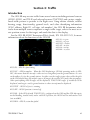
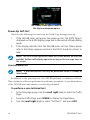
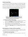
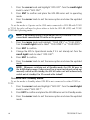
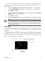
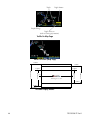
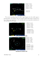
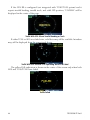
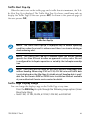
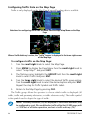
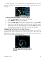
GNS 400W/500W Series SW Version 5.10
Upgrade Supplement
This supplement provides information regarding new features that have been added with
software version 5.10 for 400W/500W Series units.
You may download documents at http://fly.garmin.com or contact Garmin Customer
Support for a printed copy.
Documents That Have Been Revised For SW Verson 5.10
• GNS 400W/500W Series Pilot’s Guide & Reference,
(Garmin P/N 190-00356-00 or 190-00357-00, respectively) Rev J
• GNS 400W/500W Series Quick References,
(Garmin P/N 190-00356-01 or 190-00357-01, respectively) Rev H
• GNS 400W/500W Series Garmin Optional Displays Addendum
(Garmin P/N 190-00356-30) Rev K
Later versions of each document will include all changes from previous versions.
190-00356-37 Rev A
1
Pilot Guide Upgrade Supplements
The following table lists the previous revisions of the Pilot Guides and The Upgrade
Supplements which, taken together, provide operating information for main software
version 5.10. For instance, if the current Pilots Guide is rev G, then the v5.00 and v5.10
Upgrade Supplements should be downloaded and printed to use with the rev G manual
to provide equivalent instructions to the latest, rev J Pilots Guide.
Garmin Displays Addendum
Display Interfaces Addendum
190-00356-30
190-00356-31
H
x
G
x
x
E, F
x
x
x
D
x
x
x
x
C
x
x
x
x
x
A, B
x
x
x
x
x
J
x
H
x
x
F
x
x
x
D
x
x
x
x
C
x
x
x
x
x
A, B
x
x
x
x
x
C
190-00356-32
v3.00 Supplement
190-00356-00
190-00357-00
190-00356-33
v3.20 Supplement
400W Pilots Guide or
500W Pilots Guide
190-00356-34
v3.30 Supplement
Part Number Rev
190-00356-35
v4.00 Supplement
Pilot Guide
190-00356-36
v5.00 Supplement
Required Supplements
190-00356-371
v5.10 Supplement
Current Pilot Guides
x
x
x
1. For non-GDL 88 installations, only pages 1 through 5 of the v5.10 supplement are
required.
2
190-00356-37 Rev A
400W & 500W Series Pilot’s Guides & Quick References
Basic Approach Operations
The LP +V approach type has been added to the following table and in the appropriate
locations throughout the guides and quick references where approach types are listed.
Annunciation
Description
LPV
Localizer Performance with Vertical guidance (LPV) approach. Fly to LPV minimums. A yellow background indicates that the approach is safe to continue but
a downgrade to LNAV may occur.
LP
Localizer Performance with no vertical guidance. Fly to LP minimums. SW V
3.30, or later.
LP +V
LP +V indicates Localizer Performance with advisory vertical guidance. Fly LP
minimums down to the MDA and missed approach location. This annunciation
is available in SW Ver 5.10, or later.
L/VNAV
Lateral Navigation and Vertical Navigation (LNAV/VNAV) approach. Fly to
Lnav/Vnav minimums.
LNAV+V
GPS approach using published LNAV minima. Advisory vertical guidance is
provided.
LNAV
Lateral Navigation approach. Fly to LNAV minimums.
MAPR
Missed Approach indicates the system is providing missed approach integrity
and CDI full-scale deflection ±0.3 NM.
ENR
En route, CDI full-scale deflection is 2.0 NM or current CDI scale selection,
whichever is smaller.
TERM
Terminal, CDI full-scale deflection is 1.0 NM or current CDI scale selection,
whichever is smaller.
DPRT
Departure, indicates the system is using non-precision approach integrity. HAL
= 0.3 and CDI full-scale deflection is 0.3 NM.
OCN
Oceanic, CDI full-scale deflection is 2.0 NM.
LOW ALT
(lower window)
For LNAV+V, Lnav/Vnav, LPV, or LP+V approaches, the LOW ALT annunciation indicates the aircraft’s estimated height is lower than the Final Approach
Waypoint height by more than the current VPL plus 50 meters. This annunciation will not be active when TAWS or Terrain is operational.
While Flying an Approach
After the aircraft has passed the FAF, a loss of WAAS integrity will cause the approach to
abort instead of downgrade.
190-00356-37 Rev A
3
RNAV Approach Procedures
The 400W/500W-series allows for flying LNAV, LNAV/VNAV, LNAV + V, LP, LP +V, and LPV
approaches according to the published chart.
Description
HSI
Annunciation
L/VNAV
Lateral Navigation/Vertical Navigation.
RNAV non-precision approach with vertical guidance.
LNAV
Lateral Navigation. RNAV non-precision
approach.
LNAV + V
Lateral Navigation with Advisory Vertical
Guidance. RNAV non-precision LNAV
approach with advisory vertical guidance. The glidepath is typically denoted
by a light dashed line on the vertical
profile (Jeppeson only) with an associated glidepath angle (usually in the 3.00
degree range) and is provided to assist
the pilot in maintaining a constant vertical
glidepath, similar to an ILS glideslope.
LPV
Localizer Performance with Vertical guidance (LPV) approach. RNAV precision approach.
LP
LP indicates Localizer Performance with
no vertical guidance.
LP +V
LP +V indicates Localizer Performance
with advisory vertical guidance. This annunciation is available in SW Ver 5.10, or
later. This advisory guidance follows the
same nature as set by the LNAV +V as
shown above.
4
Minimums
Published LNAV/VNAV
minimums.
Published LNAV minimums.
Published LNAV minimums.
Published LPV minimums.
Published LP minimums.
Published LP minimums.
190-00356-37 Rev A
Changes to Messages
Approach downgraded — Use LNAV minima — This message will occur 60 seconds prior
to the FAF, if flying LNAV+V, L/VNAV, LP, LPV, or LP +V approaches and WAAS integrity parameters
have fallen below minimal limits. As a result, vertical guidance has been discontinued and the
LNAV+V, L/VNAV, LP, LPV, or LP +V approach you were flying has been downgraded.
Traffic device has failed — The 400W/500W-series unit cannot communicate with the SKY497
or TCAD and/or the SKY497 or TCAD is reporting a system failure. This can also be displayed due to
GDL 88 failure.
400W/500W Series Garmin Optional Displays
Addendum
Page 2 - Corrected AIM References
NOTE: This section on TIS Limitations is not comprehensive. Garmin
recommends the user review the TIS Limitations section of the Aeronautical
Information Manual, Sections 4-5-6 and 4-5-8.
Page 15 - Simplified NEXRAD Wx Legend. The colors and levels have not changed.
Pages 69 to 84- Updated Section 7 covering the GDL 88/88D
Extensive edits were made to the section to update information.
190-00356-37 Rev A
5
The following pages cover the GDL 88/88D interface with the
GNS 400W/500W series.
Part Seven:
Garmin GDL 88/88D Interface
Section 1: Introduction
The GDL 88/88D is a remote-mounted product that contains a 978 MHz Universal Transceiver (UAT) and a 1090 MHz receiver. The GDL 88 will transmit ownship
ADS-B data via the UAT data link. It will receive ADS-B data from other UAT and
1090ES equipped aircraft, as well as Flight Information Service Broadcast (FIS-B)
weather and TIS-B traffic from FAA ground stations. The received data may be
output to an appropriate display.
See the GDL 88 ADS-B Transceiver Pilot’s Guide, P/N 190-01122-03, for more
information about the functions of the GDL 88.
6
190-00356-37 Rev A
Section 2: FIS-B Weather
Flight Information Services (FIS) Description
Review the Limitations section in the front of this guide for the limitations that
apply to the FIS-B data.
The FIS-B Function is based on a ground-to-air data link and requires that the
appropriate ground systems are broadcasting weather data and the aircraft is within
reception range of the Ground Broadcast Transceiver (GBT). Low flying aircraft may
not receive FIS-B weather updates due to terrain blocking the GBT broadcast.
The Flight Information Services (FIS) function provides text and graphic weather
information for aircraft equipped with a GDL 88. No subscription is required for
FIS-B services.
FIS-B weather data reception requires line-of-site communication between
the receiver and the ADS-B ground station. Incomplete Regional and/or CONUS
NEXRAD imagery displayed on the MAP and FIS-B Weather Pages of the affected
products is an indicator of poor FIS-B reception.
Graphical Weather Display
NEXRAD
Graphical weather data is overlaid on the map indicating the precipitation
(intensity) detected by ground based radar for a specific area. The colors indicating
increasing levels of rainfall progresses from green for light precipitation to red for
heavy precipitation. FIS-B weather does not differentiate between liquid and frozen
precipitation. Precipitation data is color coded as follows:
FIS-B Weather Legend
A cyan checkerboard pattern indicates that no data is available for that area.
After weather data is received, the GNS will display that Region NEXRAD data
for 30 minutes and CONUS NEXRAD for 60 minutes. After the expiration time the
data will be removed, “NXRD: N/A” will be displayed.
190-00356-37 Rev A
7
UAT FIS-B Graphic Weather Info with the GDL 88
The GBT determines the extents of the weather data transmitted. The GDL 88
can receive data from several GBTs concurrently and provides the data to the GNS
for display.
Affected Areas
Any area in the continental United States (CONUS) or Alaska where the distance
from ADS-B ground stations or the combined effect of distance and low altitude is
sufficiently great to cause poor reception. A good source of information for ground
station coverage can be found at http://www.faa.gov/nextgen/flashmap/
Reception will improve in some affected areas as the FAA completes the NextGen
ADS-B ground station infrastructure. However, due to line-of-sight broadcast characteristics, operators with properly installed and functioning equipment may still
receive incomplete FIS-B data when signal reception is limited by the distance from
ground stations combined with a low altitude.
The example below displays an area where FIS-B data is degraded due to poor
reception:
Example of Areas Where FIS-B Reception Is Incomplete
8
190-00356-37 Rev A
NEXRAD Description
WSR-88D weather surveillance radar or NEXRAD (NEXt generation RADar) is
a Doppler radar system that has greatly improved the detection of meteorological
events such as thunderstorms, tornadoes, and hurricanes. An extensive network
of NEXRAD stations provides almost complete radar coverage of the continental
United States, Alaska, and Hawaii. The unobstructed range of each NEXRAD is
124 nautical miles. The update rate is 2.5 minutes for Regional NEXRAD and 15
minutes for CONUS NEXRAD.
NEXRAD Abnormalities
There are possible abnormalities regarding displayed NEXRAD images. Some,
but not all, causes of abnormal displayed information include:
• Ground Clutter
• Strobes and spurious radar data
• Sun strobes, when the radar antenna points directly at the sun
• Military aircraft deploy metallic dust which can cause alterations in radar scans
• Interference from buildings or mountains, which may cause shadows
• Scheduled maintenance may put a radar off-line
NEXRAD Limitations
Certain limitations exist regarding the NEXRAD radar displays. Some, but not
all, are listed for the user’s awareness:
• The (high resolution) Regional NEXRAD “pixels” are 1.5 minutes (1.5 nautical
miles = 2.78 km) wide by 1 minute (1 nautical miles = 1.852 km) tall. The
(medium resolution – 5 times larger than high resolution) CONUS NEXRAD
“pixels” are 7.5 minutes (7.5 nautical miles = 13.89 km) wide by 5 minutes
(5 nautical miles = 9.26 km) wide. Above 60 degrees of latitude the block
widths double to 3 minutes/nautical miles for Regional (no CONUS above
60 degrees). The intensity level reflected by the pixel will be the highest level
sampled within the area covered by each pixel.
NEXRAD Intensity
Colors are used to identify the different NEXRAD echo intensities (reflectivity)
measured in dBZ (decibels of Z). “Reflectivity” is the amount of transmitted power
returned to the radar receiver. Reflectivity (designated by the letter Z) covers a wide
range of signals (from very weak to very strong). So, a more convenient number for
calculations and comparison, a decibel (or logarithmic) scale (dBZ), is used. The
dBZ values increase as the strength of the signal returned to the radar increases.
There are three gradations for precipitation intensity.
190-00356-37 Rev A
9
NEXRAD Options
When selected for display, NEXRAD precipitation intensity information is
shown. Composite data from all of the NEXRAD radar sites in the United States
for the selected area is shown. This data is composed of the maximum reflectivity
from the individual radar sweeps. The display of the information is color-coded to
indicate the weather level severity. Information about which sites are operational or
off-line is also available (see coverage below). Refer to the legend for a description
of the color code.
The NEXRAD option has selections of Regional, CONUS, or Combined NEXRAD.
CONUS NEXRAD includes a composite of available NEXRAD radar imagery across
the 48 states. Regional NEXRAD is a composite of available NEXRAD radar imagery
in a local area, showing a more detailed image than CONUS NEXRAD.
To select CONUS NEXRAD, REGION NEXRAD, or graphic METARs
on the Nav Weather page:
1.
In the NAV group, turn the small right knob to the FIS-B Weather
page.
2.
Press the small right knob to activate selection.
3.
Turn the small right knob to select CONUS NEXRAD, REGION NEXRAD,
or METARs.
4.
Press the small right knob to save the displayed selection.
To select CONUS NEXRAD or REGION NEXRAD on the Nav Map
pages:
10
1.
In the NAV group, turn the small right knob to the Nav Map page
(Nav page 2).
2.
Press the MENU key.
3.
Turn the small right knob to select Display CONUS NEXRAD or Display
RGN NEXRAD.
4.
Press the ENT key to save the displayed selection.
190-00356-37 Rev A
Continental US NEXRAD (CONUS)
The Display CONUS NEXRAD selection shows NEXRAD radar information for
the entire continental United States.
Outside of NEXRAD
Coverage
Aircraft Position
NEXRAD Weather
NEXRAD Coverage
Weather Page With CONUS NEXRAD Displayed
Regional NEXRAD
The Display RGN NEXRAD selection shows NEXRAD radar information for the
region near the aircraft location. Regional NEXRAD is a higher resolution display of
the weather data.
Page Function Label
Select Region
NEXRAD, CONUS
NEXRAD, or METAR
Outside of NEXRAD
Coverage
NEXRAD Weather
Aircraft Position
NEXRAD Coverage
Weather Page With Region NEXRAD Display
190-00356-37 Rev A
11
Graphical METARs
When selected for display, graphic METARs (METeorological Aviation Reports)
are shown as colored flags at airports that provide METAR reports. Refer to the Legend for a description of the color code. The update rate is every five minutes and
there is a 90 minute expiration time.
NOTE: If both a GDL69 and GDL88 are interfaced to the GNS then the
textual METARS and TAF pages will show the most recent data and the
source of the data will be indicated (FIS-B or XM).
METARs are shown as colored flags at airports that provide them.
12
1.
Press MENU to display the Page Menu. Turn the large or small right
knob to highlight “Display Legend?”
2.
Press the ENT key to display the METAR legend.
190-00356-37 Rev A
Textual METARs:
1.
In the WPT group, turn the small right knob to the FIS-B Textual METAR
page. Textual METARS for the flight plan destination airport are shown
by default.
2.
To select a different airport, press the small right knob to activate the
cursor. The Airport ident will blink.
3.
Turn the small or large right knob to select the desired airport.
4.
Press the small right knob again to turn the selection cursor off.
5.
When more text is available than can be displayed, a scroll bar will be
shown on the right side of the display. Press the small right knob to
activate the cursor and turn the large right knob to scroll the text
display.
190-00356-37 Rev A
13
Terminal Area Forecast (TAF)
14
1.
In the WPT group, turn the small right knob to the TAF page. TAFs for
the flight plan destination airport are shown.
2.
To select a different airport, press the small right knob to activate the
cursor. The Airport ident will blink.
3.
Turn the small right knob to start airport selection. Use the small
and large right knobs to select the desired airport.
4.
Press the small right knob again to turn the selection cursor off.
5.
When more text is available than can be displayed, a scroll bar will be
shown on the right side of the display. Press the small right knob to
activate the cursor and turn the large right knob to scroll the text
display.
190-00356-37 Rev A
Section 3: Traffic
Introduction
The GDL 88 may receive traffic from several sources including external sources
(ADS-B, ADS-R, and TIS-B) and onboard sources (TAS/TCAS) and creates a single,
fused traffic picture to provide to the flight crew. Using relative altitude, relative
bearing, range, directionality, ground track, and other identifying information
(ICAO address, flight ID, call sign, tail number), the GDL 88 determines when
tracks from multiple sources represent a single traffic target, selects the most accurate position source for the target, and sends the data to the display.
See the GDL 88 ADS-B Transceiver PIlot’s Guide, P/N 190-01122-03, for more
information about the functions of the GDL 88.
ADS ON – in green
ADS INC – in green
ADS TEST – in white
ADS OFF – in white
ADS N/A – in white
ADS FAIL – in yellow
ADS ON - ADS-B is functioning.
ADS INC - ADS Incomplete. When the GNS displaying a GDL 88 operating mode of ADSINC, this means that the aircraft is either not receiving data from the ground stations or is not
on the address list for the ground stations. In either case the traffic picture observed by the pilot
on the GNS display does not include some or all targets observed by ATC and is thus incomplete.
Other participating ADS-B traffic will be displayed, TCAS/TCAD traffic (if installed) will be
displayed, and targets sent by ground stations to other aircraft may be displayed.
ADS TEST - ADS-B self-test is running.
ADS OFF - ADS-B function is turned off.
ADS N/A. If the GDL 88 with TCAD/TCAS is configured on the GNS and the GDL 88 reports
invalid heading, invalid track, and a valid GPS position, the ADS-B will be indicated as N/A
(not available).
ADS FAIL - ADS-B system has failed.
190-00356-37 Rev A
15
The Standby Screen appears when the
GDL 88 passes the power-up test.
Power-Up Self-Test
Check for the following test criteria on the Traffic Page during power-up:
1. If the GDL 88 series unit passes the power-up test, the Traffic Page is
displayed on the 6-NM display range and in the normal altitude display
mode.
2. If the display indicates that the GDL 88 series unit has failed, please
refer to the failure response section in the Pilot’s Guide for actions to
take.
NOTE: The FAILED message occurs when the system detects an error and
prohibits further traffic display operation as long as this message stays on
the screen.
User-initiated Test
NOTE: A user-initiated test can only be performed when in standby or
failed mode.
In addition to the power-up test, the GDL 88 performs a continuous self-test.
This continuous self-test is performed several times per minute. A user-initiated test
of the GDL 88 series unit interface can also be performed.
To perform a user-initiated test:
16
1.
In the Nav page group, turn the small right knob to select the Traffic
Page.
2.
From the Traffic Page, press MENU to display the Page Menu.
3.
Turn the small right knob to select “Self Test?” and press ENT.
190-00356-37 Rev A
Altitude Display Mode
The altitude filter will change the traffic displayed to include only those targets
within the vertical limits of the selected filter. There are four altitude display filters:
Normal (±2,700 feet), Above (-2,700 feet to +9,000 feet), Below (-9,000 feet to
+2,700 feet), and Unrestricted (±9,900 feet). The selected altitude display filter is
displayed in the upper left-hand corner of the Traffic page. The GDL 88 continues
to track up to 30 intruder aircraft within its maximum surveillance range, regardless
of the altitude display filter selected and will display up to eight intruders.
The name of the selected altitude display filter (ABV: look up,
NRM: normal, BLW: look down, or UNR: unrestricted) is displayed
in the upper left-hand corner of the Traffic Screen.
To change the Altitude Display Mode:
1. From the Traffic Page, turn the cursor on, highlight the current filter
and turn the small right knob to cycle through the options.
2. With each turn of the knob, the screen changes to display the traffic
detected within the selected altitude display range.
3. Note that confirmation is not required. The mode is changed immediately
when using the small right knob. Turn the cursor off when selection
is made.
Switching Between Standby and Operating Modes
The GDL 88 must be in operating mode for traffic to be displayed. The ability
to switch out of standby into operating mode on the ground is especially useful for
observing the airspace around the airport before takeoff.
To switch into Operating Mode:
To set the mode to Operating when GDL 88 is not connected to either TCAD
or TCAS:
190-00356-37 Rev A
17
1. Press the cursor knob and highlight “ADS OFF”. Turn the small right
knob to select “ADS ON?”.
2. Press ENT to confirm and place the GDL 88 series unit in operating
mode.
Press the cursor knob to exit the menu option and view the updated
mode.
To set the mode to Operate on the GNS units connected to GDL 88 with TCAD
or TCAS, the pilot will need to place either or both the GDL 88 (ADS) and TCAS/
TCAD the Operating mode.
3.
NOTE: If no heading source is installed then the GDL 88 and a TCAS/TCAD
cannot both commanded ON while on the ground.
1. Press the cursor knob and highlight “TCAD STBY” or “TCAS STBY”.
Turn the small right knob to select “TCAS OPER?” or “TCAD OPER?”.
2. Press ENT to confirm.
3. Change the ADS to Operational mode, if it is not already set. Turn the
small right knob to select “ADS ON?”.
4. Press ENT to confirm.
5. Press the cursor knob to exit the menu option and view the updated
mode.
NOTE: Whenever switching out of Standby mode, the GDL 88 goes to
the 6-NM display range. If your aircraft has a squat switch and you do not
manually switch out of standby, the GDL 88 series unit will automatically
switch out of standby 8 to 10 seconds after takeoff.
To switch into Standby Mode:
To set the mode to Standby when GDL 88 is not connected to either TCAD or
TCAS:
1. Press the cursor knob and highlight “ADS ON”. Turn the small right
knob to select “ADS OFF?”.
2. Press ENT to confirm and place the GDL 88 series unit in Standby mode.
3. Press the cursor knob to exit the menu option and view the updated
mode.
18
190-00356-37 Rev A
To set the mode to Standby on the GNS units connected to GDL 88 with TCAD
or TCAS, the pilot will need to place either or both ADS and TCAS/TCAD to the
Standby modes.
1. Press the cursor knob and highlight “TCAD OPER” or “TCAS OPER”.
Turn the small right knob to select “TCAS STBY?” or “TCAD STBY?”.
2. Press ENT to confirm.
3. Change the ADS to Standby mode, if it is not already set. Turn the small
right knob to select “ADS OFF?”.
4. Press ENT to confirm.
5. Press the cursor knob to exit the menu option and view the updated
mode.
NOTE: If your aircraft has a squat switch, STBY is not displayed while you
are airborne but will go into standby 24 seconds after landing. This delay
allows the GDL 88 series unit to remain in the operating mode during a
touch-and-go maneuver.
Traffic Page
Traffic can be displayed both on the Traffic Page and Nav Map page(s). When
using TCAD or TCAS, traffic can only be displayed on a Nav Map page if heading
is available.
When interfaced to a GDL 88 Datalink Sensor, GNS 400W/500W series units
can display ADS-B and TIS-B traffic on the Traffic and Nav Map Pages. When using
TCAD or TCAS, ADS-B and TIS-B traffic may be overlayed on the Map Page, but
only if a valid heading source is provided.
Altitude Display Mode
Traffic
Orientation Source (TRK or HDG)
Is Received From the GDL 88
Operating Mode
Display Range
Traffic Page
190-00356-37 Rev A
19
Traffic Banner
Traffic
Display Range
Traffic Advisory
(with no bearing information)
Traffic On Map Page
Traffic Off-Scale (Map Page)
+9,900 ft
+9,000 ft
0 ft
Drawing Not to Scale
Above (ABV)
Below (BLW)
Unrestricted (UNR)
0 ft
Normal (NRM)
+2,700 ft
+2,700 ft
-2,700 ft
-9,000 ft
-9,900 ft
Altitude Display Modes
20
190-00356-37 Rev A
ADS ON – in green
ADS INC – in green
ADS TEST – in white
ADS OFF – in white
ADS N/A – in white
ADS FAIL – in yellow
Traffic Target
Track Vector
Traffic With GDL 88
The vectors extending from the traffic targets display how the traffic target is
moving relative to the ground. The vector length is fixed and provides no indication of
how a target is moving relative to the ownship and does not provide an indication of
the threat posed by the target.
ADS ON – in green
ADS INC – in green
ADS TEST – in white
ADS OFF – in white
ADS N/A – in white
ADS FAIL – in yellow
TCAS/TCAD modes:
TCAS STBY – in white
TCAS OPER – in green
TCAS FAIL – in yellow
TCAS TEST – in white
Traffic With GDL 88 With TCAS
ADS ON – in green
ADS INC – in green
ADS TEST – in white
ADS OFF – in white
ADS N/A – in white
ADS FAIL – in yellow
TCAD modes:
TCAD STBY – in white
TCAD OPER – in green
TCAD FAIL – in yellow
TCAD TEST – in white
TCAD APR – in green
TCAD GND – in green
Traffic With GDL 88 With TCAD
190-00356-37 Rev A
21
If the GDL 88 is configured (not integrated with TCAD/TCAS system) and it
reports invalid heading, invalid track, and valid GPS position, “UNAVAIL” will be
displayed in the center of the page.
Traffic With GDL 88 and Invalid Heading or Track
If either TCAS or ADS is in failed state, valid data may still be available. Intruders
may still be displayed from the operational device.
Traffic With GDL 88 With TCAS Operating and ADS-B Failed
The yellow FAIL indication is shown in the center of the screen only when both
ADS and TCAS/TCAD have failed.
Traffic Failed
22
190-00356-37 Rev A
Traffic Alert Pop-Up
When the unit is not on the traffic page and a traffic threat is imminent, the Traffic Alert Pop-Up is displayed. The Traffic Alert Pop-Up shows a small map and can
display the Traffic Page (if the user presses ENT) or return to the previous page (if
the user presses CLR).
Traffic Alert Pop-Up
NOTE: The Traffic Alert Pop-Up is displayed only in normal operating
conditions when the aircraft is airborne and there is no terrain alerting or
dead reckoning alert.
NOTE: The Traffic Alert Pop-Up is disabled when the aircraft ground
speed is less than 30 knots or when an approach is active, unless the unit
is configured for helicopter operation as noted by the helicopter ownship
icon.
NOTE: Traffic data will be shown on the Traffic and Nav Map pages even
without heading. When using TCAD or TCAS, GDL 88 series unit traffic data
is only displayed on the Map Page if suitable aircraft heading data is available. See the Garmin 400W or 500W Series Installation Manuals available
at your authorized Garmin service center for details.
Traffic Page Display Range
You can change the display range on the Traffic Page at any time.
Press the RNG Key to cycle through the following range options (Inner
Ring/Outer Ring):
• None/1 NM, 1/2 NM, 2/6 NM, 6/12 NM, 12/24 NM, and 24/40 NM.
190-00356-37 Rev A
23
Configuring Traffic Data on the Map Page
Traffic is only displayed on the Map Page if aircraft heading data is available.
Selections for configuring traffic data are made from the Map Setup Menu on the Map
Page.
When a Traffic Advisory is active, the “Traffic” banner is displayed in the lower right corner
of the Map Page.
To configure traffic on the Map Page:
1. Turn the small right knob to select the Map Page.
2. Press MENU to display the Page Menu. Turn the small right knob to
select “Setup Map?” and press ENT.
3. The flashing cursor highlights the GROUP field. Turn the small right
knob to select Traffic and press ENT.
4. Turn the large right knob to select the desired Traffic group option.
Turn the small right knob to select the desired option and press ENT.
Repeat the step for Traffic Symbol and Traffic Label.
5. Return to the Map Page by pressing CLR.
The Traffic group allows the operator to choose which traffic is displayed (all
traffic, traffic and proximity advisories, or traffic advisories only). The traffic symbol
is the symbol used to depict the type of traffic:
24
NOTE: Proximity Advisories (PA) are displayed as solid white diamonds (may
be configured as cyan). PAs are defined as traffic within the 6.0-NM range, with
± 1200 feet of altitude separation, and not a traffic advisory (TA).
190-00356-37 Rev A
From the Map Page, you can display traffic in a thumbnail format in any of the
top three data fields (top four fields on the 500W Series) on the right side of the
Map Page.
To display Thumbnail Traffic on the Map Page:
1.
Turn the small right knob to select the Map Page.
2.
Press MENU to display the Page Menu.
3.
Turn the small right knob to select “Change Fields?” and press ENT.
4.
Select one of the top three fields (top four fields on the 500W Series).
Select TRFC from the Select Field Type List and press ENT. Note that
the thumbnail range defaults to 6 NM and cannot be changed.
Highlighting Traffic Data Using Map Panning
The Panning, function allows you to view more information about traffic by
highlighting the traffic symbol with the panning target pointer. The pointer will
move from one target to another if left active as the traffic list provided by the
GDL88 is resorted as targets change priority.
When the target pointer is placed on traffic,
the traffic range and altitude separation are
displayed.
190-00356-37 Rev A
25
To select the panning function and pan the map display:
1.
Press the small right knob to activate the panning target pointer.
2.
Turn the small right knob clockwise to move up, or turn it counterclockwise to move down.
3.
Turn the large right knob clockwise to move right, or turn it counterclockwise to move left.
4.
To cancel the Panning function and return to your present position,
press the small right knob.
When the target pointer is placed on traffic, the traffic range and altitude separation are displayed. The traffic is identified as:
TA: Traffic Advisory, PA: Proximity Advisory,
TRFC: Other Traffic
GDL 88/88D Status
The GDL 88 (D) Status page displays information about the GDL 88 operating
status and lists active faults, as well as selections for output to the GDL 88.
GDL 88 STATUS page menu allows Arming/Disarming Anon mode
and turning Pressure Altitude Reporting On/Off.
Pressure Altitude Report (PALT RPT)
The GDL 88 requires the use of an ownship pressure altitude for transmission of
required ADS-B Out data values and to calculate the vertical separation and vertical
closure from target aircraft.
1. Turn the large knob to select AUX group.
26
2.
Turn the small knob to select the GDL 88 Status page.
3.
Press MENU to display the menu.
4.
Turn the small or large right knob to highlight the desired choice
and then press ENT.
190-00356-37 Rev A
Anonymous (ANON) Mode
The Anonymous Mode, when armed, will replace the Flight ID with a temporary
randomized number for privacy while the position information will still be provided. The call sign will be sent as “VFR.” To enable Anonymous Mode, the Squawk
Code on the installed transponder must be set to the VFR code (based on the GDL
88 configuration) and the Anonymous Mode must be armed. Anonymous mode is
not available when the GDL88(D) is connected to a Mode S transponder.
1. Turn the large knob to select AUX group.
2.
Turn the small knob to select the GDL 88 Status page.
3.
Press MENU to display the menu.
Turn the small or large right knob to highlight the desired choice
and then press ENT.
Failure Response
Errors indicated by a “FAILED” message on the screen prevent continued use
of the GDL 88 Series unit. If the GDL 88 is configured (not integrated with TCAD/
TCAS system) and reports an invalid heading, invalid track, and valid GPS position,
“UNAVAIL” will be displayed in the center of the page. See the GDL 88 Status page
for information on Failure Response.
4.
GDL 88 STATUS page, lists some of the problems with the GDL 88,
that might cause the failure.
190-00356-37 Rev A
27
RYAN TCAD
Ryan TCAD is a system that provides audio and visual alerts for traffic near your
aircraft. The information from this system can be interfaced through the GDL 88 to
the GNS 400W/500W series. Operating instructions and details on the modes of
operation are described in the Ryan TCAD operator’s handbooks.
Setting Altitude Display Mode
The GDL 88 TCAD has four altitude display modes: Normal (±2,700 feet), Above
(-2,700 feet to +9,000 feet), Below (-9,000 feet to +2,700 feet), and Unrestricted
(±9,900 feet). The GDL 88 continues to track up to 30 intruder aircraft within its
maximum surveillance range, regardless of the altitude display mode selected.
The selected altitude display mode is displayed in the upper left-hand corner of
the Traffic page.
1.
While viewing the Traffic page, press the small right knob to activate
the cursor and highlight the current mode. Turn the small right knob
to cycle through the options.
2. With each turn of the knob, the screen changes to display the traffic
detected within the selected altitude display range. The 400W/500W
Series screen also displays unrestricted traffic (UNR) having a maximum
range available.
3. Press ENT to confirm and save the selected value.
TCAD Traffic Page Menu
28
1.
Press MENU to display the page menu. Turn the small or large right
knob to highlight the desired choice of commands to send to the Ryan
TCAD.
2.
With the TCAD Approach (APR) Mode selected, pressing ENT toggles
between Enabled and Disabled.
3.
With TCAD GND Mode selected, pressing ENT toggles between Enter
and Exit GND mode.
190-00356-37 Rev A
4.
Select Setup? and press ENT to reach the Setup page.
5.
Select Self Test? and press ENT to start the Self Test process. Self Test
is also performed on unit start up.
Ryan TCAD Setup
1.
From the Nav group Traffic page, press the MENU key. Turn the small
right knob to highlight “Setup?” and then press ENT.
2.
The RYAN TCAD Setup screen will now be displayed and the Baro
Pressure selection will be activated for selection. Turn the small knob
to select a numeric value and turn the large right to move the cursor
and then press ENT to save the selected value.
3.
The Ground/Field Elevation value is now activated for selection. Turn
the small knob to select a numeric value and turn the large right to
move the cursor and then press ENT to save the selected value.
4.
The Volume field is now activated for selection. Turn the small knob
to select a numeric value and turn the large right to move the cursor
and then press ENT to save the selected value.
190-00356-37 Rev A
29
Traffic Watch
If your 400W/500W-series unit is connected to other equipment providing traffic alert information (e.g., L3 SKYWATCH™ or RYAN TCAD), a traffic alert pop-up
is provided to display traffic information. This allows you to monitor traffic conditions from ANY page and quickly identify traffic hazards.
Traffic
Watch
Window
30
Traffic
Information
1.
In the Aux group, select “Data Field Configuration” from the Setup 1
Page.
2.
Turn the small right knob to select the desired data field option. The
following options are available:
3.
Press ENT to accept the selection.
190-00356-37 Rev A
© 2014 GARMIN Corporation
GARMIN International, Inc.
1200 East 151st Street, Olathe, Kansas 66062, U.S.A.
Tel. 913/397.8200 or 866/739.5687
Fax 913/397.8282
Garmin AT, Inc.
2345 Turner Rd., S.E., Salem, Oregon 97302, U.S.A.
Tel. 503/581.8101 or 800/525.6726
Fax. 503/364.2138
Garmin (Europe) Ltd.
Liberty House, Bulls Copse Road, Hounsdown Business Park,
Southhampton, SO40 9LR U.K.
Tel. +44 (0) 870 850 1243
Fax +44 (0) 238 052 4004
GARMIN Corporation
No. 68, Jangshu 2nd Road, Shijr, Taipei County, Taiwan
Tel. 886/2.2642.9199
Fax 886/2.2642.9099
www.garmin.com
http://fly.garmin.com
April 2014 190-00356-37 Rev A