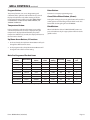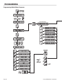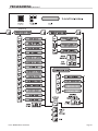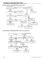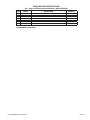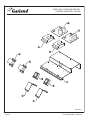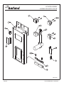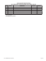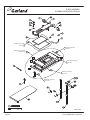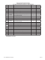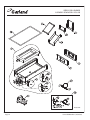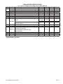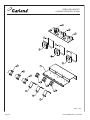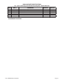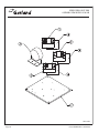
1
SERVICE MANUAL JACK IN THE BOX GAS XPRESS GRILLS, MODELS XG24-JIB, XG36-JIB FOR YOUR SAFETY: DO NOT STORE OR USE GASOLINE OR OTHER FLAMMABLE VAPORS OR LIQUIDS IN THE VICINITY OF THIS OR ANY OTHER APPLIANCE WARNING: IMPROPER INSTALLATION, ADJUSTMENT, ALTERATION, SERVICE OR MAINTENANCE CAN CAUSE PROPERTY DAMAGE, INJURY, OR DEATH. READ THE INSTALLATION, OPERATING AND MAINTENANCE INSTRUCTIONS THOROUGHLY BEFORE INSTALLING OR SERVICING THIS EQUIPMENT NOTE: THIS MANUAL PERTAINS TO ALL XPRESS GRILL MODELS LISTED ABOVE. THE READER/OPERATOR MUST INTERPRET ITS CONTENTS TO APPLICABLE NEEDS. HOWEVER, IF THERE IS ANY QUESTION OF INTERPRETATION OF ANY LITERATURE PERTAINING TO GARLAND GRILLS, PLEASE CONTACT OUR CUSTOMER SERVICE DEPARTMENT AT ONE OF THE PHONE NUMBERS LISTED BELOW. GARLAND COMMERCIAL INDUSTRIES, LLC 185 East South Street Freeland, Pennsylvania 18224 Phone: (570) 636-1000 Fax: (570) 636-3903 Part##JIBSM08 Rev 7(08/04/09) (08/04/09) Part JIBSM08 Rev.6 MODEL NUMBERS: XG24-JIB,XG36-JIB PLEASE READ ALL SECTIONS OF THIS MANUAL AND RETAIN FOR FUTURE REFERENCE. THIS PRODUCT HAS BEEN CERTIFIED AS COMMERCIAL COOKING EQUIPMENT AND MUST BE INSTALLED BY PROFESSIONAL PERSONNEL AS SPECIFIED. CAUTION: THIS EQUIPMENT MUST ONLY BE OPERATED UNDER AN APPROVED HOOD SYSTEM IN THE COMMONWEALTH OF MASSACHUSETTS THIS PRODUCT MUST BE INSTALLED BY A LICENSED PLUMBER OR GAS FITTER. For Your Safety: Post in a prominent location, instructions to be followed in the event the user smells gas. This information shall be obtained by consulting your local gas supplier. GARLAND COMMERCIAL RANGES, LTD. 1177 Kamato Road, Mississauga, Ontario L4W 1X4 CANADA Phone: 905-624-0260 Fax: 905-624-5669 © 2008 Garland Commercial Industries, LLC1 Page TABLE OF CONTENTS DIMENSIONS AND SPECIFICATIONS, XG24-JIB MODEL . . . . . . . . . . . . . . . . . . . . . . . . . . . . . . 4 DIMENSIONS AND SPECIFICATIONS, ++XG36-JIB MODEL . . . . . . . . . . . . . . . . . . . . . . . . . . . 5 Plug Configuration . . . . . . . . . . . . . . . . . . . . . . . . . . . . . . . . . . . . . 6 INTRODUCTION . . . . . . . . . . . . . . . . . . . . . . . . . . . . . . . 7 Warranty . . . . . . . . . . . . . . . . . . . . . . . . . . . . . . . . . . . . . . . . . . . . . . . 7 Shipping Damage Claim Procedure . . . . . . . . . . . . . . . . . . . . . 7 SAFETY . . . . . . . . . . . . . . . . . . . . . . . . . . . . . . . . . . . . . . . 7 UNIT INSTALLATION . . . . . . . . . . . . . . . . . . . . . . . . . . . 9 Rating Plate Location . . . . . . . . . . . . . . . . . . . . . . . . . . . . . . . . . . . 9 General Information . . . . . . . . . . . . . . . . . . . . . . . . . . . . . . . . . . . . 9 National Codes Requirements: . . . . . . . . . . . . . . . . . . . . . . . . . . 9 Gas Connections, and Pipe Sizing: . . . . . . . . . . . . . . . . . . . . . . . 9 Appliances Equipped with Casters: . . . . . . . . . . . . . . . . . . . . 10 Electrical Connections: . . . . . . . . . . . . . . . . . . . . . . . . . . . . . . . 10 Accessory Kit – Main Gas Inlet: . . . . . . . . . . . . . . . . . . . . . . . . 10 Accessory Kit – Electrical Supply Lines: . . . . . . . . . . . . . . . . 11 Electrical Connection Terminal Block Connection . . . . . . 12 Grease Bucket: . . . . . . . . . . . . . . . . . . . . . . . . . . . . . . . . . . . . . . . 12 Ventilation and Clearance: . . . . . . . . . . . . . . . . . . . . . . . . . . . . 12 Changing to a different type of gas . . . . . . . . . . . . . . . . . . . . 12 Burner Air Adjustment . . . . . . . . . . . . . . . . . . . . . . . . . . . . . . . . 13 Igniter Adjustment . . . . . . . . . . . . . . . . . . . . . . . . . . . . . . . . . . . 13 GRILL CONTROLS . . . . . . . . . . . . . . . . . . . . . . . . . . . . 14 Master Power Switch: . . . . . . . . . . . . . . . . . . . . . . . . . . . . . . . . 14 LED Indicators: . . . . . . . . . . . . . . . . . . . . . . . . . . . . . . . . . . . . . . . 14 Display: . . . . . . . . . . . . . . . . . . . . . . . . . . . . . . . . . . . . . . . . . . . . . . 14 Product Buttons (0-9): . . . . . . . . . . . . . . . . . . . . . . . . . . . . . . . . 14 Power Button: . . . . . . . . . . . . . . . . . . . . . . . . . . . . . . . . . . . . . . . . 14 Program Button: . . . . . . . . . . . . . . . . . . . . . . . . . . . . . . . . . . . . . . 15 Temperature Button: . . . . . . . . . . . . . . . . . . . . . . . . . . . . . . . . . 15 Up/Down Arrow Buttons; 2 Functions: . . . . . . . . . . . . . . . . 15 Enter Button: . . . . . . . . . . . . . . . . . . . . . . . . . . . . . . . . . . . . . . . . . 15 Cancel/Raise Platen Button, (Green): . . . . . . . . . . . . . . . . . . 15 Black Button: . . . . . . . . . . . . . . . . . . . . . . . . . . . . . . . . . . . . . . . . . 15 Main Pre-Programed Product Items . . . . . . . . . . . . . . . . . . . 15 PLATEN ZEROING . . . . . . . . . . . . . . . . . . . . . . . . . . . . 16 OPTIONAL ACCESSORIES . . . . . . . . . . . . . . . . . . . . 18 RELEASE MATERIAL INSTALLATION . . . . . . . . . . . 19 NORMAL OPERATION . . . . . . . . . . . . . . . . . . . . . . . . 20 Installing Release Material: . . . . . . . . . . . . . . . . . . . . . . . . . . . . 20 Lighting Instructions: . . . . . . . . . . . . . . . . . . . . . . . . . . . . . . . . . 20 Shut Down Instructions . . . . . . . . . . . . . . . . . . . . . . . . . . . . . . . 20 To Cook in Two-Sided Mode: . . . . . . . . . . . . . . . . . . . . . . . . . . 20 To Cook in Flat Grill Mode: . . . . . . . . . . . . . . . . . . . . . . . . . . . . 20 Page 2 Enter Standby Mode: . . . . . . . . . . . . . . . . . . . . . . . . . . . . . . . . . 21 Exit Standby Mode: . . . . . . . . . . . . . . . . . . . . . . . . . . . . . . . . . . . 21 To Display the Current Temperatures: . . . . . . . . . . . . . . . . . 21 To View Settings for a Menu Item: . . . . . . . . . . . . . . . . . . . . . 21 To Clean the Grill: . . . . . . . . . . . . . . . . . . . . . . . . . . . . . . . . . . . . . 21 PLATEN SET: . . . . . . . . . . . . . . . . . . . . . . . . . . . . . . . . . . . . . . . . . . 21 EXTENDED TIME: . . . . . . . . . . . . . . . . . . . . . . . . . . . . . . . . . . . . . 22 INSTANT ON TIME: . . . . . . . . . . . . . . . . . . . . . . . . . . . . . . . . . . . . 22 START DELAY: . . . . . . . . . . . . . . . . . . . . . . . . . . . . . . . . . . . . . . . . 22 CLEANING AND MAINTENANCE . . . . . . . . . . . . . . 22 Cleaning During Operation: . . . . . . . . . . . . . . . . . . . . . . . . . . . 22 Daily Cleaning: . . . . . . . . . . . . . . . . . . . . . . . . . . . . . . . . . . . . . . . 22 PROGRAMMING . . . . . . . . . . . . . . . . . . . . . . . . . . . . . 24 Programming Modes/Menu Sequence: . . . . . . . . . . . . . . . 24 Menu Items... To Change the Cook Time of a Product: . . . . . . . . . . . . . . . . 26 To Turn Platen, (2-Sided), Cooking On/Off: . . . . . . . . . . . . . 26 To Change Upper Platen Set Temperature: . . . . . . . . . . . . . 26 To Change Grill Set Temperature: . . . . . . . . . . . . . . . . . . . . . . 26 To Change Product Gap Setting: . . . . . . . . . . . . . . . . . . . . . . 26 To Change Product Button, “Key” Assignment . . . . . . . . . 27 To Change a Product Name: . . . . . . . . . . . . . . . . . . . . . . . . . . . 27 System Info... To View Recovery Time - Upper Platen: . . . . . . . . . . . . . . . . 27 To View Recovery Time - Grill: . . . . . . . . . . . . . . . . . . . . . . . . . 27 To View the Garland Part Number: . . . . . . . . . . . . . . . . . . . . . 27 To View the Flash Number: . . . . . . . . . . . . . . . . . . . . . . . . . . . . 28 To View the Software Number: . . . . . . . . . . . . . . . . . . . . . . . . 28 To View the Download Number: . . . . . . . . . . . . . . . . . . . . . . . 28 System Setup To Change temperature Units, (°F or °C): . . . . . . . . . . . . . . . 28 To Change Gap Setting Display Units: . . . . . . . . . . . . . . . . . 28 To Change the Alarm Volume: . . . . . . . . . . . . . . . . . . . . . . . . . 29 To Change the Key Chirp: . . . . . . . . . . . . . . . . . . . . . . . . . . . . . 29 To Change Probe Calibration - Upper: . . . . . . . . . . . . . . . . . 29 To Change Probe Calibration - Grill: . . . . . . . . . . . . . . . . . . . 29 To Change Platen Set: . . . . . . . . . . . . . . . . . . . . . . . . . . . . . . . . . 30 To Change Instant-On Time: . . . . . . . . . . . . . . . . . . . . . . . . . . 30 To Change Control Type: . . . . . . . . . . . . . . . . . . . . . . . . . . . . . . 30 To Turn Extended Time On/Off: . . . . . . . . . . . . . . . . . . . . . . . 30 To Change the Grill Function: . . . . . . . . . . . . . . . . . . . . . . . . . 31 To Change the Start Delay: . . . . . . . . . . . . . . . . . . . . . . . . . . . . 31 To Change the Alarm Mode: . . . . . . . . . . . . . . . . . . . . . . . . . . 31 To Turn Clean Mode On/Off: . . . . . . . . . . . . . . . . . . . . . . . . . . 31 To Add a Product Name in Library: . . . . . . . . . . . . . . . . . . . . 31 To Modify a Product Name in Library: . . . . . . . . . . . . . . . . . 32 Service Mode To Change SCK Address: . . . . . . . . . . . . . . . . . . . . . . . . . . . . . . 32 To Perform Limit Switch Test: . . . . . . . . . . . . . . . . . . . . . . . . . . 32 Part # JIBSM08 Rev 7 (08/04/09) TABLE OF CONTENTS continued CALIBRATION . . . . . . . . . . . . . . . . . . . . . . . . . . . . . . . 33 Bi-Weekly Calibration: . . . . . . . . . . . . . . . . . . . . . . . . . . . . . . . . 33 Probe Locations: . . . . . . . . . . . . . . . . . . . . . . . . . . . . . . . . . . . . . . 34 TROUBLESHOOTING . . . . . . . . . . . . . . . . . . . . . . . . . 35 ERROR MESSAGES: PROBE ERROR: . . . . . . . . . . . . . . . . . . . . . . . . . . . . . . . . . . . . . . . . 35 PLATEN DOWN ERROR: . . . . . . . . . . . . . . . . . . . . . . . . . . . . . . . 35 PLATEN UP ERROR: . . . . . . . . . . . . . . . . . . . . . . . . . . . . . . . . . . . 35 HEATING ERROR: . . . . . . . . . . . . . . . . . . . . . . . . . . . . . . . . . . . . . 35 COMM ERROR: . . . . . . . . . . . . . . . . . . . . . . . . . . . . . . . . . . . . . . . 35 MOTOR OVER CURRENT: . . . . . . . . . . . . . . . . . . . . . . . . . . . . . . 35 MOTOR ERROR: . . . . . . . . . . . . . . . . . . . . . . . . . . . . . . . . . . . . . . . 35 IGNITION ERROR: . . . . . . . . . . . . . . . . . . . . . . . . . . . . . . . . . . . . . 35 FLASHING LED(S): . . . . . . . . . . . . . . . . . . . . . . . . . . . . . . . . . . . . 35 TECHNICAL TROUBLESHOOTING . . . . . . . . . . . . . 36 Master Power (ON / OFF) Switch turned ON Power light or indicator is not lit . . . . . . . . . . . . . . . . . . . . . . 36 Low Internal Product Temperatures . . . . . . . . . . . . . . . . . . . 36 Controller Displays “Too Hot” . . . . . . . . . . . . . . . . . . . . . . . . . . 37 Controller Displays “FAULTY ELEMENT OR SHORTED PROBE” -Only 1 or 2 zones LED lights are RED . . . . . . . . . . 38 Controller displays “PROBE ERROR” . . . . . . . . . . . . . . . . . . . . 39 Controller Displays “HEATING ERROR or PROBE ERRORPLATEN and GRILL LED’s are RED (Both Sides) . . . 40 Inconsistent Or Erratic Internal Product Temperature . . 40 Controller Display is BLANK, Main Power (ON / OFF) light or indicator is LIT . . . . . . . . . . . . . . . . . . . . . . . . . . . . . . . . 41 Master Power (ON / OFF) Switch turned ON Power Light in On - Grill is not heating . . . . . . . . . . . . . . . . 42 Controller Displays “MOTOR OVER CURRENT” Platen does not move at all . . . . . . . . . . . . . . . . . . . . . . . . . . . 43 Controller Displays “MOTOR OVER CURRENT” Platen stops and moves to lower limit . . . . . . . . . . . . . . . . . 43 Controller Displays “IGNITION FAILURE” No flame at all . . . . . . . . . . . . . . . . . . . . . . . . . . . . . . . . . . . . . . . . 44 Controller Displays “IGNITION FAILURE” Flame does not light at all . . . . . . . . . . . . . . . . . . . . . . . . . . . . . 44 Controller Displays “IGNITION FAILURE” Module is sparking, flame comes on and goes out . . . . 45 Part # JIBSM08 Rev.6 (08/04/09) LINEAR ACTUATOR REPLACEMENT . . . . . . . . . . . 46 PARTS LIST . . . . . . . . . . . . . . . . . . . . . . . . . . . . . . . . . . 49 XG24-JIB XPRESS GRILL GAS XPRESS - GRILL COMPLETE VIEW . . . . . . . . . . . . . . . . . . . . . . 50 XPRESS GRILL ACTUATOR . . . . . . . . . . . . . . . . . . . . . . . . . . . . . 52 XPRESS GRILL PLATEN . . . . . . . . . . . . . . . . . . . . . . . . . . . . . . . . 54 XPRESS GRILL BURNER . . . . . . . . . . . . . . . . . . . . . . . . . . . . . . . . 56 XPRESS GRILL COMPONENT BRACKET . . . . . . . . . . . . . . . . . 58 XPRESS GRILL HEAT SINK . . . . . . . . . . . . . . . . . . . . . . . . . . . . . . 60 REVISION HISTORY . . . . . . . . . . . . . . . . . . . . . . . . . . . . . . . . . . . . 62 XG36-JIB XPRESS GRILL GAS GRILL COMPLETE ASSEMBLY . . . . . . . . . . . . . . . . . . . . . . . . . . 64 ACTUATOR ASSEMBLY . . . . . . . . . . . . . . . . . . . . . . . . . . . . . . . . 68 PLATEN ASSEMBLY . . . . . . . . . . . . . . . . . . . . . . . . . . . . . . . . . . . 70 XPRESS GRILL BURNER . . . . . . . . . . . . . . . . . . . . . . . . . . . . . . . . 72 XPRESS GRILL BRACKET . . . . . . . . . . . . . . . . . . . . . . . . . . . . . . 74 XPRESS GRILL HEAT SINK . . . . . . . . . . . . . . . . . . . . . . . . . . . . . . 76 WIRING HARNESS AND DESCRIPTION WHERE USED . . . . 78 ACCESSORIES AND TOOLS . . . . . . . . . . . . . . . . . . . . . . . . . . . . 79 GAS TUBING . . . . . . . . . . . . . . . . . . . . . . . . . . . . . . . . . . . . . . . . . . 80 REVISION HISTORY . . . . . . . . . . . . . . . . . . . . . . . . . . . . . . . . . . . . 81 WIRING DIAGRAM . . . . . . . . . . . . . . . . . . . . . . . . . . . 82 CONTROLLER MENU ITEMS . . . . . . . . . . . . . . . . . . 84 TEMPERATURE CONVERSION (F / C) . . . . . . . . . . . 85 Page 3 DIMENSIONS AND SPECIFICATIONS, XG24-JIB MODEL Model Total kW Load XG24-JIB 8.66 Loading kW Per Phase Nominal Amps Per Line 208/240V 3ph 208V 3-Phase Delta 240V 3-Phase Delta X-Y X-Z Y-Z 2.66 3.33 2.66 X Y Z X Y Z 24.90 22.14 24.90 21.61 19.19 21.61 6’ (1.83m) electric cord and plug included in supplied accessory kit: 240V models are supplied with a #4-10AWG cord with a NEMA 5-30P plug, kit # 4525509. 208V models are supplied with a #4-6AWG cord with a NEMA 15-50P plug, kit # 4524785. Clearances Entry Gas Pressure Installation Supply (min.) Total Gas Input Operating Crated Uncrated Sides Rear NAT PRO NAT PRO BTU/Hr kW 47-1/2" (1207mm) 32" (813mm) 6" (152mm) 3" (76mm) 7.0" WC 11.0" WC 3.5" WC 3.5 " WC 66,000 19.4 TOP HEATER 11 1/2" TOP VIEW [292mm] G 24" [610mm] 1 3/4" [44mm] Shipping: Weight 575Lbs/ 234Kg, 45 Cubic Feet Garland products are not approved or authorized for home or residential use, but are intended for commercial applications only. Garland will not provide service, warranty, maintenance or support of any kind other than in commercial applications Gas input ratings shown here are for installations up to 2,000 Ft. (610m) above sea level. Specify altitudes over 2,000 Ft. 40" [1016mm] GRILL PLATE 24" X 24" [610mm X 610mm] 35" [889mm] 26 3/16" [665mm] GRILL PLATE HEIGHT FRONT VIEW 9" [229mm] Page 4 TOLERANCE +/- 1/8" [3mm] 61 1/4" [1556mm] 34" [864mm] RIGHT SIDE VIEW 35 5/8" [905mm] 3/4" GAS INLET MIN 6" [152mm] MAX 9" [229mm] Part # JIBSM08 Rev 7 (08/04/09) DIMENSIONS AND SPECIFICATIONS, XG36-JIB MODEL Nominal Amps Per Line Total Loading kW Per Phase kW 208/240V 3ph 208V 3-Phase Delta 240V 3-Phase Delta Load X-Y X-Z Y-Z X Y Z X Y Z Model XG36-JIB 12.99 4.00 4.99 4.00 37.43 33.30 37.43 32.43 28.90 32.43 6’(1.83m) electric cord and plug is included in the supplied kit : 208V or 240V models are supplied with a #4-6AWG cord with a NEMA 15-50P plug, kit #4524785 Clearances Entry Crated Gas Pressure Installation Uncrated 47-1/2" 40-3/4" (1207mm) (1035mm) Supply (min.) Total Gas Input Operating Sides Rear NAT PRO NAT PRO BTU/Hr kW 6" (152mm) 3" (76mm) 7.0" WC 11.0" WC 3.5" WC 3.5" WC 99,000 29.1 TOP HEATER 11 1/2" TOP VIEW [292mm] Shipping: Weight 965Lbs/ 438Kg, 59 Cubic Feet Garland products are not approved or authorized for home or residential use, but are intended for commercial applications only. Garland will not provide service, warranty, maintenance or support of any kind other than in commercial applications Gas input ratings shown here are for installations up to 2,000 Ft. (610m) above sea level. Specify altitudes over 2,000 Ft. 1 3/4" [44mm] G 24" [610mm] 40" [1016mm] GRILL PLATE 24" X 36" [610mm X 914mm] 46 15/16" [1191mm] 26 3/16" [665mm] GRILL PLATE HEIGHT FRONT VIEW 36 1/8" [918mm] Part # JIBSM08 Rev.6 (08/04/09) 12 5/8" [321mm] TOLERANCE +/- 1/8" [3mm] 34" [864mm] 61 1/4" [1556mm] RIGHT SIDE VIEW 35 5/8" [905mm] 3/4" GAS INLET MIN 6" [152mm] MAX 9" [229mm] Page 5 SPECIFICATIONS continued Plug Configuration The grill is supplied with an electrical power supply cord and plug to match the specific voltage as it was constructed. The following table shows the correct plug configuration to match the model and voltage. Xpress Grill Cord and Plug Configuration P/N (includes electrical and gas inlet plumbing) Plug Type Cord Gauge Supplied NEMA Plug Y X GND 4524785 4-6AWG Model Voltage (3ph Delta) Maximum Current (Amps) Minimum Cord Gauge XG24-JIB 208 24.90 4-10AWG 208 37.43 4-6AWG 240 32.43 4-8AWG 240 21.61 4-10AWG 15-50P XG36-JIB Z Y X GND 4525509 4-10AWG 15-30P XG24-JIB Z Page 6 Part # JIBSM08 Rev 7 (08/04/09) INTRODUCTION The Garland Xpress grill, for Jack in the Box provides a method for efficient two-sided cooking, while accommodating a variety of products. The unit will also serve as a flat grill, and meets all of Jack in the Box’s standards for safety, efficiency, and cleanliness. Warranty This warranty covers defects in material and workmanship under normal use providing that: a) The equipment has not been accidentally or intentionally damaged, altered or misused. b) The equipment is properly installed, adjusted, operated and maintained in accordance with national and local codes and in accordance with the installation instructions provided with this product. c) The warranty serial number affixed to the appliance by Garland has not been defaced, obliterated or removed. d) An acceptable report for any claim under this warranty is supplied to Garland. than overland, and overtime costs of repair. We exclude broken glass, paint and porcelain finish, surface rust, gasket material, ceramic material, light bulbs and fuses from normal coverage. We exclude damage or dysfunction caused by fire, flood, and like “Acts of God” that are beyond the control of The Garland Group. The Garland Group’s liability on a claim of warranty shall not exceed the price of the material and/or service, which caused the claim. This warranty is limited and is in lieu of all other warranties, expressed or implied. The Garland Group, our employees, or our agents shall not be held liable for any claims of personal injury or consequential damage or loss. This warranty gives you specific legal rights, and you may have other rights which vary from state to state. Shipping Damage Claim Procedure Please note that the Garland equipment was carefully inspected and packed by skilled personnel before leaving the factory. The transportation company assumes full responsibility for safe delivery upon acceptance of the equipment. The equipment warranty coverage remains in force for one (1) year (parts and labor) from the date the equipment is put into operation. What to do if the equipment arrives damaged: The Garland Group agrees to repair or replace, at it’s option, any part that proves to be defective in materialor workmanship at no charge for the part or normal labor. 2. Be sure to note, "visible loss or damage," on the freight bill or express receipt and have the person making the delivery sign it. We assume no responsibility for installation, adjustments, diagnosis, or normal maintenance such as: lubricationof springs or valves. We exclude failures caused by erratic voltage or gas supplies. We assume no responsibility for travel costs beyond 100 miles round trip, travel other 3. Concealed loss or damage: if damage is unnoticed until the equipment is unpacked, notify the freight company immediately, (within 15 days), and file a concealed damage claim. 1. File a claim immediately regardless of the extent of damage. SAFETY Always follow these safety precautions when operating the Xpress Grill. • DO NOT operate the Xpress grill unless it has been properly installed and grounded. • THIS GRILL MUST be operated by persons who have been given adequate training. • DO NOT operate the Xpress grill unless all service and access panels are in place and fastened properly. • THIS EQUIPMENT MUST ONLY BE OPERATED UNDER AN APPROVED HOOD SYSTEM. The Garland Xpress Grill is a semi-automatic cooking appliance. The upper platen is lowered automatically, following the manual, two-handed initiation of the cooking cycle, and the upper platen is raised automatically upon completion of the cooking cycle. • DO NOT OPERATE THE GRILL UNLESS IT HAS BEEN COMMISSIONED (START-UP) BY A FACTORY AUTHORIZED SERVICE CENTER. • DO NOT operate the grill without reading the operation manual. Part # JIBSM08 Rev.6 (08/04/09) Page 7 SAFETY continued When two sided cooking, the area between the upper platen and the griddle plate should be regarded as a “danger zone.” During two sided cooking the operator must not be within this danger zone. When used as a flat grill, then this area is no longer a danger zone, the platens do not move. WARNING: After turning the master power switch to the START position, the grill will go through initialization. If the upper platens are in the lowered position they will return to their raised upper position. This movement takes approximately 8 seconds. For whatever reason, be it cleaning, maintenance, or normal operation, any exposed person must use extreme caution if within this danger zone. MAINTENANCE - the platen support arms carriage block bearing bushings, the platen adjuster nuts, the platen support (shoulder) bolt and the cam follower should be checked annually for wear. Should there be any noticeable play in the bearing bushings and any visible wear on the platen adjuster nuts, platen support bolts or cam follower, then they must be replaced. In two side cooking the upper platen remains in the lowered position by nature of its own weight. It is not locked down. It can be raised by lifting up on the handle on the front of the platen, which pivots the platen about it rear mounting point. The Xpress Grill may during its operation emit airborne noise equivalent to a continuous A weighted sound pressure level of 73dB(A). The Xpress grill must only be used for single and two sided cooking of foodstuffs in a Jack in the Box store and must not be used for any other purpose. WARNING: To avoid serious personal injury: • DO NOT attempt to repair or replace any part of the Xpress Grill unless all main power supplies to the grill have been disconnected. • USE EXTREME CAUTION in setting up, operating and cleaning the Xpress Grill to avoid coming in contact with hot grill surfaces or hot grease. Suitable protective clothing should be worn to prevent the risk of burns. • DO NOT clean this appliance with a water jet. • DO NOT apply ICE or COLD WATER to a HOT grill surface. • NOTE all warning labels and markings affixed to the grill, since they call attention to further dangers and necessary precautions. HAZARD COMMUNICATION STANDARD, (HCS) - The procedures in this manual include the use of chemical products. These chemical products will be printed in bold face, followed by the abbreviation (HCS) in the text portion of the procedure. See the Hazard Communication Standard, (HCS) manual for the appropriate Material Safety Data Sheet(s), (MSDS). Page 8 MAINTENANCE - the audible alarm that sounds on platen lowering, platen raising and 5 seconds before the completion of the cooking cycle is to advise the operator that the platen is about to move. The function of this device may be tested by pushing the left hand CANCEL button. If no sound is heard, ensure that the alarm volume is not set to low in SYSTEM SETUP. If there is still no sound then a service engineer should be called out to rectify the fault. SERVICE AND CLEANING - The grill is secured in the grill bay by the installer using two anchors that lock onto the front casters. If the grill is to be moved out of the bay for cleaning or service, remove the anchor from each caster by turning the knob counterclockwise to loosen the retainer. When the retainer is free of the caster, lay the assembly aside on the floor. After service or cleaning is complete, return the grill to its position in the bay and reattach the anchors by placing the retainer on the caster post and turning the knob clockwise to tighten. NOTE: For safety reasons, the grill must be secured in the grill bay in this manner before operation can resume. Part # JIBSM08 Rev 7 (08/04/09) UNIT INSTALLATION Rating Plate Location IMPORTANT: Rating plates for this appliance are located in two places: 1) inside back panel on left side, 2) under front control panel on center. General Information This equipment must be installed by a competent factory trained, certified, licensed and / or authorized service or installation person. WARNING: This appliance must be properly grounded. Installation shall be made with the gas connector that has been specified by The Jack in the Box Corporation and is supplied loose with the grill. The quick disconnect fitting and gas shut off valve must be installed in the direction indicated on their outer body. NOTE: When checking gas pressure, be sure that all other equipment on the same gas line is on. The appliance and its individual shut-off valve must be disconnected from the gas supply piping system during any pressure testing of that system pressures in excess of 1/2 PSIG (3.45kPa, 14”WC). Prior to installation, the four casters, supplied loose with the grill, must be securely located on the underside of the base. The casters fitted with a brake must be located at the front of the grill. Adequate clearance must be provided for servicing and proper operation. This appliance should be connected to a potential equalization system. A labeled equipotential bonding point is fitted to the rear of the grill. The type of gas for which the grill is equipped is stamped on the data plate on the inside rear of the unit and on the lower front panel. Connect a grill stamped for Natural Gas (High (H) or Low (L) Calorific Value) only to Natural Gas; connect those stamped for Propane Gas only to Propane gas. It is recommended that this grill be connected to a residual current (earth leakage) device with a tripping current not exceeding 30mA. The leakage current of this grill will not exceed 5mA. CAUTION: Prior to installation, check the electrical supply to ensure input voltage and phase match the equipment voltage rating and phase. See data plate located rear left side of grill and lower front panel. Grill is to be located directly under ventilation system. Once installed in the grill station underneath the ventilation system, the platens, in their highest position, must not interfere with the lower lip of the ventilation system hood. The raised position of each platen is adjusted by raising or lowering the upper of the two microswitches, (limit switches), in the rear of the grill. The lower microswitch position must not be adjusted. Grill plate must be level front to back, side to side and diagonally. This leveling must be done with the unit under the hood and in it’s normal operational position to prevent warping of the grill plate. NOTE: Once the platen elevation is adjusted, set the mechanical over-run bolts in the rear of the unit to prevent accidental over-run in the event of failure of the upper microswitch. NOTE: Fuses are installed to prevent damage in the event of failure of the upper microswitch. National Codes Requirements: The installation must conform to the National Fuel Gas Code ANSI Z223.1-1998 or latest edition, NFPA No. 54 – latest edition and National Electrical Code ANSI/NFPA 70-1990 or latest edition and/or local code to assure safe and efficient operation. In Canada, the installation must comply with CSA B149.1 and local codes where applicable. In Canada, electrical connection must comply with applicable sections of the Canadian Electrical Code, C22.1 - 1990, latest edition, “Safety Standard for Installation, Part 1” and C22.2- No. O-M 1982 latest edition , “General Requirements, Part 2”. Gas Connections, and Pipe Sizing: The size of the gas line is very important. If the line is too small, the gas pressure at the burner manifold will be low. This will cause slow recovery and delayed ignition. The incoming gas pressure line should be a minimum of 1-1/2". All grills require a 3/4" connection. Before connecting new pipe the pipe must be blown out to dispose of any foreign particles. These particles will cause improper operation. When using thread compound, use small amounts on male threads only. Use a compound that is not affected by the chemical action of LP gases. Avoid applying compound to the first two threads to prevent clogging of the burner orifices and control valve. Have the installer check all gas plumbing with a soap solution for leaks. DO NOT USE matches, candles or other ignition sources in checking for leaks. Part # JIBSM08 Rev.6 (08/04/09) Page 9 UNIT INSTALLATION continued The grill must be disconnected from the gas supply system when pressure testing of that system at pressures in excess of 1/2 psi (3.45kPa). Check the data plate to determine the proper type of gas before connecting the quick disconnect or piping from the building gas supply. An incoming gas pressure test nipple is provided on the incoming gas manifold for pressure checks. Electrical Connections: All electrically operated appliances must be electrically grounded in accordance with local codes; or in the absence of local codes, with the latest edition of National Wiring Regulations. A wiring diagram is located on the rear panel of the grill. See rating plate in rear of grill, or lower front panel for proper voltages. Accessory Kit – Main Gas Inlet: Minimum incoming gas pressure for Natural Gas is 6" W.C. Maximum incoming gas pressure for Natural Gas is 13" W.C. (Accessory kit part numbers 4524785 or 4525509 and also includes electrical supply lines, see next section). Minimum incoming gas pressure for Propane is 10" W.C. Maximum incoming gas pressure for Propane is 13" W.C. Each griddle is supplied with an extended rear gas manifold kit., with the following parts. Burner operating gas pressure can be checked at the outlet side of the gas valve at the pressure test point. DESCRIPTION PART DRAWING QTY. Burner manifold pressure for Natural Gas must be 3.2" W.C.; Burner pressure for Propane must be 3.5" W.C. 3/4”x 3/4” 90 Degree Elbow 1 To adjust the burner pressure, remove the sealing screw from the pressure test nipple, connect a manometer, remove the sealing cap on the gas valve regulator, turn on the grill, adjust the screw in the regulator to give the correct pressure, turn off the grill, refit the regulator sealing cap, remove the manometer, replace the seal screw in the test nipple and test for gas leaks. Nipple Assembly 1 Manifold Support Bracket 1 10-24 x 1/2 Quadrex Pan HD Type F Screw 4 Gas pressures should be checked by the local Gas Company or an authorized service agency only. Test all piping and connections for gas leaks. A rich soap solution should be used for this purpose. Never use a flame. Appliances Equipped with Casters: 1. The installation shall be made with a connector that complies with the Standard for Connectors for Moveable Gas Appliances, ANSI Z21.69/CSA 6.16, Addenda Z21.69B2006/CSA 6.16B-2006 (or latest edition), and a quickdisconnect device that complies with the Standard for Quick Disconnects for Use with Gas Fuel, ANSI Z21.41/ CSA 6.9, Addenda Z21.41A-2005/CSA 6.16A-2005 (or latest edition). Installation of Kit: A. Install the elbow on the end of manifold (3/4” NPT) underneath the griddle, tighten and align with the elbow facing the back of the unit. Refer to Photo A. 2. The front casters on the appliance are equipped with brakes to limit the movement of the appliance without placing any strain on the connector or quick-disconnect device or its associated piping. 3. Please be aware; required restraint is attached to a bracket (which is located on the rear caster closest to the gas connection), and if disconnection of the restraint is necessary; be sure to reconnect the device after the appliance has been returned to its original position. Page 10 Photo A Part # JIBSM08 Rev 7 (08/04/09) UNIT INSTALLATION continued B. Install the nipple assembly into the elbow (3/4” NPT) Refer to Photo A C. Install the manifold support bracket over the nipple attaching it to the circular bracket on the nipple. Do not tighten screws. Refer to Photo B Installation of Cord And Plug With Strain Relief: 1. Remove the left grease bucket support attached by two metal screws and the stainless steel left side body panel attached by five metal screws. 2. Remove the cord & plug and strain relief assembly from the accessory kit. Refer to photo D. Photo B D. Adjust the manifold support bracket flush with the rear gas support bracket. Refer to Photo B E. Tighten the loose screws of the manifold support bracket. Refer to Photo B F. Lock the two brackets together using two screws. Refer to Photo C Photo D 3. Remove the locknut from at the end of the cord. Refer to photo E. Photo C Accessory Kit – Electrical Supply Lines: The accessory kit also contains electric power cord and plug and has a stain relief suited for each unit. Refer to Plug Configuration in SPECIFICATIONS and Photo D Part # JIBSM08 Rev.6 (08/04/09) Photo E Page 11 UNIT INSTALLATION continued 4. Insert loose wires and strain relief cord end through the hole at the bottom of the unit. Refer to photo F and secure with locknut. Refer to photo E. Note: see diagram below for connections to terminal block. Wire leads from Cord and Plug Main Terminal Block of Grill Green-Ground G White - Z Z Black - Y Y Red - X X Photo F Grease Bucket: 5. Attached wire ends to terminal block as shown in next section and referenced in wiring diagrams at back of this manual. The griddle is supplied with two stainless steel side grease buckets that must be installed before the unit is used. Each bucket slides into position along stainless steel supports. 6. Reinstall the side panel and grease bucket support with metal screws. The external electrical connection should appear as in photo G. Ventilation and Clearance: One of the most important considerations for efficient grill operation is proper ventilation and air supply. Insure the grill is installed so the products of combustion are removed efficiently and the ventilation system does not produce drafts that interfere with proper burner operation. Proper operation of exhaust fans (speed, rotation and adjustment) is essential. In addition to the exhaust system the make-up air system, (HVAC), for the kitchen is the air supply for the combustion air for the burners. Proper incoming air is essential for all gas operated equipment. Poor incoming make-up will cause inefficient burner operation, delayed ignition and possible burner failure. Any ventilation system will break down if improperly maintained. The duct system, the hood, and the filters must be cleaned on a regular basis and kept grease free. Photo G Electrical Connection Terminal Block Connection All electrically operated appliances must be electrically grounded in accordance with local codes; or in the absence of local codes, with the latest edition of National Wiring Regulations. A wiring diagram is located behind the rear panel of the grill. See rating plate in rear of grill, or lower front panel for proper voltages. Page 12 The room containing the grill is required to have a permanent air vent. The minimum effective area of the vent shall be 0.7 in.² per kW. Air vents shall be of such a size to compensate for the effects of any extract fan in the premises. Changing to a different type of gas Changing from one gas type to another must only be done by a Qualified Gas Engineer and according to local regulations. Part # JIBSM08 Rev 7 (08/04/09) UNIT INSTALLATION continued The gas valve, enrichment tube igniter and orifice must be changed to that supplied by the Authorized Service Agency for the gas you are changing to. On completion of changing these three components, you should test all joints for leaks, verify that the manifold pressure is adjusted to the value given in the specification pages in this manual, and repeat the burner air adjustment procedure. This is to be found on the following page in this manual. When the burner is correctly adjusted, the alternate rating plate decal must be placed over the existing rating plates to reflect the new category for which the grill is set. To change from one gas type to another within the same category (High to Low Calorific Value Natural Gas or vice versa), change the orifice to that supplied by the Authorized Service Agency. Burner Air Adjustment 1. The Xpress Grill gas model burner is a stainless steel rectangular assembly that receives forced air from a fan mounted below the burner. The fan air quality can be slightly adjusted if the flame quality is poor to the point that the flame sensor will be unreliable. 1. Loosen the two 5\16” hex head #10 screws just outboard of the igniter. This allows the igniter and its bracket vertical movement. 2. With the Microamp meter in the flame sense line, and the adjustment screws just loose enough to be able to move the igniter assembly up and down, ignite the burner and move the igniter up and down until the maximum Microamp reading is achieved. 3. Tighten up the adjuster screws and the job is complete. Igniter Inspection The ignitor is next to the flame sensor in the burner compartment. Normally, it should not require any adjustment. If, however, the gap between the ignitor tip and the burner is too great, or the ignitor seems to generate a weak spark, replace the ignitor, and recheck the new component for normal operation. 2. Loosen the lock nut holding the air adjustment in place. Slowly turn the air adjustment out (counterclockwise). The flame should be stable (no lifting) and be 1/8” to 1/4” predominately blue. Igniter Adjustment The Igniter location is factory set and does not normally require adjustment. Adjustment should only be conducted if the Micro-Amp (µA) reading taken by placing a MicroAmp (µA) meter in line between the ignition module and the flame sense wire reads below 0.22 Microamps (µA). The normal reading is around 0.80 (µA) to 1.5 (µA). If the reading is low, the igniter can be a moved up or down to achieve the proper signal. The following is a description of the process. IGNITOR FLAME SENSOR Note: the correct air fuel mixture and gas pressures must be obtained before proceeding with igniter adjustment Part # JIBSM08 Rev.6 (08/04/09) Page 13 GRILL CONTROLS WHEN PUSHED SIMULTANEOUSLY: "START COOK TIME COUNTDOWN" (flat grill cooking) OR "LOWER PLATEN" (two-sided cooking) LED INDICATORS DISPLAY CANCEL/ RAISE PLATEN BUTTON PRODUCT BUTTONS ON OFF MASTER POWER SWITCH POWER BUTTON PROGRAM BUTTON TEMPERATURE BUTTON ENTER BUTTON DOWN ARROW BUTTON UP ARROW BUTTON Master Power Switch: Display: Controls power to the grill and must be turned “ON” to start operation. The controller display will be active when the switch is “ON”. The controller display will contain information relevant to each operation in both cook and program modes. LED Indicators: There are two, (2), indicator lights, indicating the temperature status of each control’s heat zones; one, (1), on the upper platen, (top light), and one, (1), on the grill surface. Each light can display three, (3), different colors, indicating temperature status for the corresponding zone. Red: The zone is too hot, (more than 79°F/45°C over the set temperature), or heat zone failure. Amber: The zone is calling for heat. Product Buttons (0-9): Buttons 0-9 can be assigned to product items. Buttons 9 and 0 are used to move the cursor left or right when creating or modifying product names in “PROD NAME LIB” program mode. Power Button: After the main power switch is turned on, this button will put the control into cook mode. If pressed again, the control will go back to displaying “OFF.” Green: The zone is at or above the set temperature. Page 14 Part # JIBSM08 Rev 7 (08/04/09) GRILL CONTROLS continued Program Button: Enter Button: The primary function is to access Programming and Calibration of the grill. Push and hold for five (5) seconds. Display will ask for the code. After entering code, five programming features will be accessible “MENU ITEMS,” “SYSTEM INFO,”“SYSTEM SETUP,”“SERVICE MODE,” and “PRODUCT NAME LIB.” Function is to accept programming steps. Cancel/Raise Platen Button, (Green): During the cooking cycle, pressing this button will cancel the cooking timer and return the grill to the “IDLE” mode. This button will also bring the grill out of STANDBY. Temperature Button: Black Button: In the Cook mode, each time the button is pressed the current temperature for one zone is displayed. The grill temperature is displayed first followed by the platen temperature. After five (5) seconds, the display will return to the menu item selected. When both Black and Green “CANCEL/RAISE” buttons are pressed simultaneously, the upper platen will lower to the griddle surface. Up/Down Arrow Buttons; 2 Functions: 1. In the cook mode, the Up/Down Arrow Buttons will cycle through the different menu items. 2. In the program mode, the Up/Down Arrow Buttons will change the value of the current setting. Main Pre-Programed Product Items Product Name Menu Name Button Name Cook Time Gap Setting Top Temp Bottom Temp Assign to # Fajitas Fajitas FAJI 1:16 0.300 425 335 1 Sausage Sausage SAUS 2:00 0.380 425 335 2 Regular Regular REG 1:15 0.300 425 335 3 Jumbo Jumbo JUMBO 2:50 0.470 425 335 4 Chicken Fillet Chicken CHIC 1:40 0.460 425 335 5 Sirloin Patties SIRLOIN SIRLOIN 2:00 0.600 425 335 6 Chicken Strip Chicken Strip CHK STRP 1:27 0.430 425 335 7 Grilled Onions Onions ONIONS 3:00 FLAT 425 335 8 *LTO 9 *LTO = Limited Time Offer = presently left open. Part # JIBSM08 Rev.6 (08/04/09) Page 15 PLATEN ZEROING Turn Master power switch “ON”, wait for controllers to display “OFF”. Note: Release sheets should not be installed during this procedure. 1. Press and hold displayed. for three, (3) seconds. “ENTER CODE” is 2. Using the Product buttons, 0-9 enter the code, (1251). “ENTER CODE **** ” is displayed. 3. Press to enter the Programming Mode. “PROGRAMMING MODE MENU ITEMS” is displayed. 4. Press two, (2) times in succession to display “PROGRAMMING MODE SYSTEM SETUP.” 5. Press six, (6) times. “PLATEN SET +/- XX” is displayed. (XX=numbers that will vary from grill to grill.) 6. Allow time for grill to heat and turn ready. Press both the Cancel (Green) and Standby (Black) buttons simultaneously to lower the upper platen. Press the Cancel (Green) button to raise the platen. Now, press both the Cancel (Green) and (Black) Buttons to re-lower the platen. 10.Move next to the left front adjuster and raise the platen until the gapping tool fits snugly between the upper platen and grill surface. 11.Next go to the left rear adjuster and raise the platen until the gapping tool fits snugly between the upper platen and grill surface. 12.Move next to the right front adjustment and raise the platen until the gapping tool fits snugly between the upper platen and grill surface. 13.Repeat steps 9-12 one or more times until gapping tool fits snugly between the upper platen and grill surface at all four adjustment points without further adjustment. (See diagram below.) 14.Replace the platen adjuster locking caps “hollow side down” and tighten snugly. Replace platen adjuster caps. 15.Repeat steps 9-14 for each platen. 7. Remove platen adjuster caps from all four adjustment points on each platen. Remove the four locking caps from the adjustment points. 8. Using the adjusting tool lower platen until adjusting tool touches the arm assembly. Insert gap tool directly below platen adjusters. 9. With gapping tool, adjust right rear of platen until the gapping tool fits snugly between the upper platen and grill surface. Page 16 Part # JIBSM08 Rev 7 (08/04/09) PLATEN ZEROING continued Platen Gapping Tool (PN 1838701) r we t Lo on Fr Left Ra Ba ise Rig ck ht “No-Go” “Go” Platen leveling should be done from one corner to the opposite corner. The adjuster nuts should be turned opposite of one another. Platen Adjusting Tool (PN 4523323) This end to remove Adjuster Locking Cap This end to remove Grease Cap and to make adjustments to the adjuster nuts Platen Adjuster Cap (PN 1859102) Platen Adj Lock Nut (PN 1859103) Shoulder Bolt (PN 8005401) Platen Adjuster Nut (PN 1859101) Part # JIBSM08 Rev.6 (08/04/09) Page 17 OPTIONAL ACCESSORIES Teflon Sheet - 1799302 Teflon Clip - 1851303 Grill Squeegee - 1868201 Teflon Tool - 4525560 Page 18 Part # JIBSM08 Rev 7 (08/04/09) RELEASE MATERIAL INSTALLATION The following procedures are the procedures for installing the Teflon sheets on to the upper platen on the Garland Xpress grill. The components shown below are included with your grill when purchased. Slide release material rod through hemmed end of the release material sheet. Holding the bottom of the release material sheet in place, gently pull the sheet toward the front of the platen. Thread the front edge of the release material sheet behind the release material bar on the front of the platen, then around the top and down over the front of the bar as shown. Place locking clips over release material sheet and press into place over release material bar. RELEASE MATERIAL BAR RELEASE MATERIAL LOCKING CLIP (1) Hook release material rod on brackets located at the rear of the upper plate RELEASE MATERIAL UPPER PLATEN (side view) FRONT OF GRILL Check alignment and tightness of release material against upper platen. UPPER PLATEN (side view) RELEASE MATERIAL HOOK RELEASE MATERIAL ROD RELEASE MATERIAL SHEET REAR OF GRILL NOTE: Make sure release material fits smoothly over upper platen. Installing release material sheets too tight may cause premature failure of the sheet. Release sheets are reversible and should be flipped over and reattached on a daily basis. For instructions on cleaning release sheets, see Step 17, Under Daily Cleaning in Cleaning and Maintenance section. A release material sheet must be replaced when: • Product sticks to release material. • Carbon build-up ruins taste or appearance. • Tearing occurs in the sheet’s cooking area. • Release material coating is worn off sheet. Part # JIBSM08 Rev.6 (08/04/09) Page 19 NORMAL OPERATION Installing Release Material: For installation instructions, see section on RELEASE MATERIAL INSTALLATION. A release material sheet must be replaced when: • Product sticks to release material. • Carbon build-up ruins taste or appearance. • Tearing occurs in the sheet’s cooking area. • Release material coating is worn off sheet. Lighting Instructions: 1. Ensure that the flexible gas hose is connected to the grill and the power cord is plugged into the receptacles. 2. Turn the main power switch ON and allow the controls to go through the power-up self-check. Once the control panel displays the word “OFF” the unit is ready to begin the heating process. 3. Press . The control will automatically initiate the heating cycle. The burner will ignite and heat until the temperature specified by the menu item has been obtained. 2. The controller regulates the platen and grill temperatures to the set temperatures of the product selected and reads “TOO COOL” or “TOO HOT” with “MENU ITEM”, until the grill attains the set temperature range for the item. NOTE: If the display reads either “TOO COOL” or “TOO HOT” the upper platen will not lower and initiate a cooking sequence. 3 After loading the product onto the grill, press the green CANCEL/RAISE PLATEN BUTTON and BLACK button simultaneously. A cook cycle starts and the upper platen lowers if the product selected is clamshell recipe. 4 To cancel a cook cycle at anytime press the green CANCEL/RAISE PLATEN BUTTON and the upper platen will rise if the product recipe selected is clamshell recipe. 5. During a cook cycle, the display shows the product recipe name in the first line and the remaining cook time count down in the second line. 6 When the cook timer reaches one, (1), second remaining a pre-time-out alarm sounds alerting the operator. 7 When the cooking time has been completed the platen raises automatically. On the controller the “PRODUCT NAME” and the word “REMOVE” will be displayed and an audible alert will sound. If ignition of the burner does not occur on the first trial, the bottom indicator light will flash amber. If the burner(s) do not light within four trials for ignition, the control will display a flashing warning, “IGNITION ERROR.” The flashing amber light will turn to solid red and an audible alarm will sound. If this occurs, turn the main power switch off, wait 5 minutes, and then repeat steps 2 and 3. If after 2nd try and the control still produces the IGNITION ERROR refer to Ignition failure in TECHNICAL TROUBLE SHOOTING section. 1. To start a cook cycle select a product recipe by using the product keys (1 through 9) or by using the UP/DOWN keys or to select a product recipe. Shut Down Instructions 1. To shut down the unit at any time, switch the main power switch to the off (non-lit) position. 2. For extended shut down periods, switch the main power switch to the off position, disconnect the unit from the gas supply line and unplug electrical connections. To Cook in Two-Sided Mode: 1. To start a cook cycle select a product recipe by using the product keys (1 through 9) or by using the UP/DOWN keys or to select a product recipe. The display alternately blinks the recipe and the word SELECTED 2 times then the recipe displays continuously. Page 20 8. Pressing the green CANCEL/RAISE PLATEN BUTTON stops the audible alert and the unit will revert back to IDLE mode. To Cook in Flat Grill Mode: The display alternately blinks the recipe and the word SELECTED 2 times then the recipe will be displayed continuously. 2. The controller regulates the grill temperature to the set temperature of the product selected and reads “TOO COOL” or “TOO HOT” with “MENU ITEM”, until the grill attains the set temperature range for the item. NOTE: If the display reads either “TOO COOL” or “TOO HOT” it will not initiate a cooking sequence. 3 After loading the product onto the grill, press the green CANCEL/RAISE PLATEN BUTTON and BLACK button simultaneously. That will start a cook cycle if the product selected is clamshell recipe. Part # JIBSM08 Rev 7 (08/04/09) NORMAL OPERATION continued 4 To cancel a cook cycle at anytime the press the green CANCEL/RAISE PLATEN BUTTON . 5. During a cook cycle, the display shows the product recipe name in the first line and the remaining cook time count down in the second line. 6. The display shows the “SEAR” or “FLIP” alarm message with flashing in the second line if the current cooking product is flat recipe and the sear time or flip time is not zero. 7. A cook alarm sounds with a repeating beep pattern. Pressing the black RAISE button acknowledges the “SEAR” or “FLIP” alarm message if the alarm field in system setup is set to MANUAL. 8. The “SEAR” or “FLIP” alarm message stops after 5 seconds if the alarm field in system setup is set to AUTO. 9. When a cook is complete, the display shows the product recipe name in the first line and a flashing “REMOVE” message in the second line. A repeating beeping alarm also sounds. 10.Pressing the black RAISE button cancels the cook done alarm. 11.The unit reverts back to IDLE mode. Enter Standby Mode: Stand by mode is used during slow periods to conserve energy with out a complete shut down of the unit. When cooking temperatures are again required, pre-heat cook temperature/time is reduced. Stand by mode temperatures can be adjusted, see the PROGRAMING section. 1. Select Standby Mode by pressing “STANDBY” is displayed. or until 2. Press the GREEN (‘CANCEL/RAISE’) and the BLACK buttons at the same time. As soon as the upper platen moves down, the display will read “STANDBY MODE.” (Note: The first time Standby Mode is entered, the display will prompt the operator to press ENTER after pressing the GREEN and BLACK buttons.) To Display the Current Temperatures: 1. Press the button and repeat for each zone to be displayed... 1st press - LOWER GRILL ZONE 2nd press - UPPER PLATEN NOTE: The temperatures may be displayed at any time, including during a cooking cycle. To View Settings for a Menu Item: 1. Enter Programming; Menu Items, (see Programming) 2. Press 3. Use 4. Press to enter “PROGRAMMING MODE MENU ITEMS” and to choose the desired Menu Item. to scroll through settings for the chosen item. To Clean the Grill: 1. To start a CLEAN MODE select the clean mode recipe by pressing product key 10 or by using the UP/DOWN keys or to select the clean mode recipe. 2. The controller regulates the platen and grill temperatures to the set temperatures of the clean mode recipe. The display shows the message “CLEAN MODE” in the first line and the actual grill temperature in the second line. 3. Press the ENTER key to initiate the clean mode. 4. The display SHOWS the message “READY TO CLEAN” with flashing in the second line when the actual temperature is reached (or greater than the set temperatures of clean mode recipe (default 250 F for both the platen and grill)). A 5 second repeating beep pattern is sounded. 5. Press the ENTER key again, the heater’s control for the platen and grill are turned off and the display shows the message “CLEANING” with flashing in the second line. 6. Press the ENTER key again to exit the CLEAN MODE. The display shows the message “STANDBY” in the first line. The control transitions to “STANDBY MODE” and preheats to idle condition. Exit Standby Mode: PLATEN SET: 1. Press the GREEN (‘CANCEL/RAISE’) button. The upper platen will raise and the display will read “CANCEL” with an audible alarm. This function allows the platen to be moved up or down once it is parallel to the grill surface. Values range from –160 to +160. Part # JIBSM08 Rev.6 (08/04/09) Page 21 NORMAL OPERATION continued EXTENDED TIME: START DELAY: This option will add 6, 4 and 2 seconds to the time of the next three cooks respectively if the grill has had no activity for 5 minutes. Provided the temperature is not 25°F above set temperature for either the grill or the platen. This number is how long the operator must hold the GREEN (‘CANCEL/RAISE’) and BLACK buttons to start a cooking cycle for 2-sided recipes only. There will be one beep when the cook is started and another beep when the START DELAY time is reached. If the GREEN (‘CANCEL/RAISE’) and BLACK buttons are released before that time the cook will be canceled. If Yes is toggled press enter to allow the user to pick from 1 to 5 seconds in 0.5 second increments using and . INSTANT ON TIME: This can be set in the range of 00:00 to 00:40. Instant on will turn on the heat zone(s) as soon as a cook cycle starts. CLEANING AND MAINTENANCE Tools: JIB Hi-Temp Grill Cleaner (HCS), JIB All Purpose Super Concentrate (HCS), JIB NO-SCRATCH (Pad and Pad Holder), a suitable container, High-Temperature Pan Brush and Grill Cloth, Stainless Steel Pan filled with lukewarm water, Protective Gloves,, (to protect hands from heat), Grill Squeegee and Grill Scraper. Warning: The upper platen surface and edges are very hot! To prevent burn injuries, use extreme caution when wiping down release sheets and platen edges. Important: Frequently throughout the day, (at least 4 times per hour), thoroughly wipe down the release sheets and platen edges with a damp grill cloth. Cleaning During Operation: Daily Cleaning: Warning: The upper platen surface and edges are very hot! To prevent burn injuries, use extreme caution when wiping down release sheets and platen edges. 1. Press the CLEAN button, or item “CLEAN MODE.” or to obtain the menu 2. Press to acknowledge that Clean Mode is desired. This will cause the appliance (grill and platen, if selected) to heat to the Clean Temperature. 3. “READY TO CLEAN” will be displayed when the grill is at the proper cleaning temperature and an audible alarm will sound. 1. After each product load is removed, Use a grill scraper to scrape grease on lower grill plate from front to back only. Do not scrape left to right across the lower grill plate with the grill scraper. 4. To exit Clean Mode, press 2. Use a grill squeegee to clean release material sheet on upper platen in a downward motion. Do not press hard against the release material sheet to prevent scratching or tearing. 6. Wipe down the exposed surface of the release sheet with a clean, damp cloth. 3. Push the grease to the rear of the grill, or pull it to the front trough. Then, squeegee the grease into the buckets on either side. Do not use the scraper for this step. 4. Use a clean, damp cloth to clean back splash and bullnose areas as needed during operation. Note: To increase life of release material sheets, wipe them down with a folded clean, damp cloth at least four times during each hour of operation. Page 22 . Display will show “OFF.”” 5. Wearing protective gloves, empty and replace the grease troughs. Note: the edge of the grill above the grease troughs gets a build up of grease, wipe down every time the grease bucket is emptied. CAUTION this edge is hot. 7. Remove the release sheet locking clips and bars. 8. Scrape only the lower grill surface with a grill scraper, and squeegee any residue into the grease troughs with a grill squeegee. Caution: Do not scrape or otherwise scratch the upper platens. The use of metal scrapers, abrasive pads, or wire brushes will permanently damage the surface of the upper platens. Part # JIBSM08 Rev 7 (08/04/09) CLEANING AND MAINTENANCE continued 9. Open one packet of high-temperature grill cleaner, (several cleaners may be available on the market), and empty the contents into a suitable container. (One packet will clean one grill.) 10. Firmly attach a no-scratch pad to a pad holder. 11. Dip the no-scratch pad into the grill cleaner, and spread a light coating of grill cleaner over the entire platen surface, back, front, and side edges of both upper platens. DO NOT SCRUB. (Note: use very limited cleaning solution on top of platens) 12. After applying the grill cleaner, lightly scrub the platen surface, and all four edges with the no-scratch pad until all the soil has been liquefied by the grill cleaner. For stubborn soils, apply additional grill cleaner and lightly scrub. DO NOT RINSE THE PLATENS AT THIS TIME. 13. Starting at the back of the lower grill, spread a light coating of grill cleaner over the surface. DO NOT SCRUB. 14. After applying the grill cleaner, lightly scrub the grill surface with the No-Scratch Pad until all the soil has been liquefied. Caution: Ice, cold water, or large quantities of water must never be applied to the grill plate or upper platen. Severe damage to the grill will occur! 17.Clean the release sheets as follows: A) Place the sheets on the lower grill. Scrub both sides of the sheets with the same no-scratch pad used on the grill. B) Rinse both sides of the sheets with a clean, wet cloth. 18.Rinse the lower grill by flooding the surface twice with lukewarm water. Squeegee after each rinse. 19.Wipe the lower grill surface, backsplash, bullnose, and hood with a clean, damp cloth. 20.When cleaning is completed, you may turn the “MASTER POWER” (rocker) switch off. AFTER CLEANING, apply a thin coat of fresh shortening to the lower grill surface only. Wipe down the surrounding areas. Empty, wash, rinse, and replace the grease troughs. 15. Rinse the upper platens with a dripping wet cloth. Do not use excessive water on the top of the platens. 16. Carefully pour small quantities of lukewarm water onto the grill while brushing the surface, backsplash, and bullnose with a pot brush or equivalent hightemperature brush. Continue until the water no longer boils away and the grill remains wet. Squeegee dry. Part # JIBSM08 Rev.6 (08/04/09) Page 23 PROGRAMMING Programming Modes/Menu Sequence: System Information System Information Page 24 26 26 26 26 26 26 26 26 26 26 27 27 27 27 27 27 27 27 27 27 28 28 28 28 28 28 Part # JIBSM08 Rev 7 (08/04/09) PROGRAMMING continued System Set-up System Set-up Part # JIBSM08 Rev.6 (08/04/09) 31 31 32 32 32 32 28 28 28 28 29 29 29 29 29 29 29 29 30 30 Service Mode 30 30 30 30 32 32 30 30 32 32 31 31 31 31 31 31 31 31 Service Mode Page 25 PROGRAMMING continued Menu Items... 5. Use To Change the Cook Time of a Product: 6 Press three, (3) times to display “(MENU ITEM) UPPER TEMP XXX” displayed in °F or °C. 1. Press and hold displayed. for three, (3) seconds. “ENTER CODE” is 2. Using the Product buttons, 0-9 enter the code, (1251). “ENTER CODE **** ” is displayed. 3. Press to enter Programming Mode. “PROGRAMMING MODE MENU ITEMS” is displayed. 4. Press 5. Use 6. Press 7. Use . “MENU ITEMS STANDBY” is displayed. and to choose the desired Menu Item. to display “(MENU ITEM) COOK TIME XX:XX” and to adjust the cook time. and to choose the desired Menu Item. 7. Use and to change the set temperature to the desired value. 8. Press to save the changes. 9. Press twice to exit. To Change Grill Set Temperature: 1. Press and hold displayed. for three, (3) seconds. “ENTER CODE” is 2. Using the Product buttons, 0-9 enter the code, (1251). “ENTER CODE **** ” is displayed. 8. Press to save the changes. 3. Press to enter the Programming Mode. “PROGRAMMING MODE MENU ITEMS” is displayed. 9. Press twice to exit. 4. Press . “MENU ITEMS STANDBY” is displayed. To Turn Platen, (2-Sided), Cooking On/Off: 5. Use 1. Press and hold displayed. 6. Press four, (4) times to display “(MENU ITEM) GRILL TEMP XXX” displayed in °F or °C. for three, (3) seconds. “ENTER CODE” is and to choose the desired Menu Item. 2. Using the Product buttons, 0-9 enter the code, (1251). “ENTER CODE **** ” is displayed. 7. Use and to change the set temperature to the desired value. 3. Press to enter the Programming Mode. “PROGRAMMING MODE MENU ITEMS” is displayed. 8. Press to save the changes. 9. Press twice to exit. 4. Press 5. Use . “MENU ITEMS STANDBY” is displayed. and to choose the desired Menu Item. 6. Press twice to display “(MENU ITEM) UPPER PLATEN YES/NO “. 7. Use and to turn upper platen on or off. 8. Press to save the changes. 9. Press twice to exit. To Change Upper Platen Set Temperature: 1. Press and hold displayed. for three, (3) seconds. “ENTER CODE” is 2. Using the Product buttons, 0-9 enter the code, (1251). “ENTER CODE **** ” is displayed. 3. Press to enter the Programming Mode. “PROGRAMMING MODE MENU ITEMS” is displayed. 4. Press Page 26 . “MENU ITEMS STANDBY” is displayed. To Change Product Gap Setting: 1. Press and hold displayed. for three, (3) seconds. “ENTER CODE” is 2. Using the Product buttons, 0-9 enter the code, (1251). “ENTER CODE **** ” is displayed. 3. Press to enter the Programming Mode. “PROGRAMMING MODE MENU ITEMS” is displayed. 4. Press 5. Use . “MENU ITEMS STANDBY” is displayed. and to choose the desired Menu Item. 6. Press five, (5) times to display “GAP XXX” displayed in inches or mm. 7. Use and value. to change the gap setting to the desired 8. Press to save the changes. 9. Press twice to exit. PROGRAMMING continued To Change Product Button, “Key” Assignment 1. Press and hold displayed. for three, (3) seconds. “ENTER CODE” is 2. Using the Product buttons, 0-9 enter the code, (1251). “ENTER CODE **** ” is displayed. 3. Press to enter the Programming Mode. “PROGRAMMING MODE MENU ITEMS” is displayed. 4. Press 5. Use . “MENU ITEMS STANDBY” is displayed. and to choose the desired Menu Item. 6. Press six, (6) times to display “ASSIGN TO KEY (0-9 or NONE)”. 7. Use and to change the key, (Product Button), assignment, and replace any previous assignments to that key. 8. Press to save the changes. 9. Press twice to exit. To Change a Product Name: 1. Press and hold displayed. for three, (3) seconds. “ENTER CODE” is 2. Using the Product buttons, 0-9 enter the code, (1251). “ENTER CODE **** ” is displayed. 3. Press to enter the Programming Mode. “PROGRAMMING MODE MENU ITEMS” is displayed. 4. Press 5. Use . “MENU ITEMS STANDBY” is displayed. and to choose the desired Menu Item. 6. Press seven, (7) times to display “PRODUCT NAME (CHOSEN ITEM)” 7. Use and to cycle through the available product names until the desired name is achieved. 8. Press to save the changes. You will automatically return to “PROGRAMMING MODE MENU ITEMS”. 9. Press to exit. System Info... To View Recovery Time - Upper Platen: 1. Press and hold displayed. for three, (3) seconds. “ENTER CODE” is 3. Press to enter the Programming Mode. “PROGRAMMING MODE MENU ITEMS” is displayed. 4. Press one, (1) time to display “PROGRAMMING MODE SYSTEM INFO.” 5. Press to view the upper recovery time. “RECOVERY UPPER XXXX” is displayed. 6. Press INFO”. to return to “PROGRAMMING MODE SYSTEM 7. Press to exit. To View Recovery Time - Grill: 1. Press and hold displayed. for three, (3) seconds. “ENTER CODE” is 2. Using the Product buttons, 0-9 enter the code, (1251). “ENTER CODE **** ” is displayed. 3. Press to enter the Programming Mode. “PROGRAMMING MODE MENU ITEMS” is displayed. 4. Press one, (1) time to display “PROGRAMMING MODE SYSTEM INFO.” 5. Press two, (2), times to view the grill recovery time. “RECOVERY GRILL XXXX” is displayed. 6. Press to return to “PROGRAMMING MODE SYSTEM INFO”. 7. Press to exit. To View the Garland Part Number: 1. Press and hold displayed. for three, (3) seconds. “ENTER CODE” is 2. Using the Product buttons, 0-9 enter the code, (1251). “ENTER CODE **** ” is displayed. 3. Press to enter the Programming Mode. “PROGRAMMING MODE MENU ITEMS” is displayed. 4. Press one, (1) time to display “PROGRAMMING MODE SYSTEM INFO.” 5. Press three, (3), times to view the Garland Part Number for the grill. “GARLAND PART # X…X” is displayed. (number varies by grill). 6. Press INFO”. to return to “PROGRAMMING MODE SYSTEM 7. Press to exit. 2. Using the Product buttons, 0-9 enter the code, (1251). “ENTER CODE **** ” is displayed. Part # JIBSM08 Rev.6 (08/04/09) Page 27 PROGRAMMING continued To View the Flash Number: 1. Press and hold displayed. for three, (3) seconds. “ENTER CODE” is 2. Using the Product buttons, 0-9 enter the code, (1251). “ENTER CODE **** ” is displayed. 3. Press to enter the Programming Mode. “PROGRAMMING MODE MENU ITEMS” is displayed. 4. Press one, (1) time to display “PROGRAMMING MODE SYSTEM INFO.” 5. Press four, (4), times to view the Flash Number. “FLASH NUMBER X…X” is displayed. (Flash number varies by grill). 5. Press six, (6), times to view the Download Number. “DOWNLOAD NUMBER X…X” is displayed. (Download number varies by grill). 6. Press INFO”. to return to “PROGRAMMING MODE SYSTEM 7. Press to exit. System Setup To Change temperature Units, (°F or °C): 1. Press and hold displayed. for three, (3) seconds. “ENTER CODE” is 6. Press INFO”. to return to “PROGRAMMING MODE SYSTEM 2. Using the Product buttons, 0-9 enter the code, (1251). “ENTER CODE **** ” is displayed. 7. Press to exit. 3. Press to enter the Programming Mode. “PROGRAMMING MODE MENU ITEMS” is displayed. To View the Software Number: 1. Press and hold displayed. for three, (3) seconds. “ENTER CODE” is 2. Using the Product buttons, 0-9 enter the code, (1251). “ENTER CODE **** ” is displayed. 3. Press to enter the Programming Mode. “PROGRAMMING MODE MENU ITEMS” is displayed. 4. Press two, (2) times. “PROGRAMMING MODE SYSTEM SETUP” is displayed. 5. Press to enter system setup. “TEMP DISPLAY FAHRENHEIT (or CELSIUS)” is displayed. 6. Press to change the temperature units to either Fahrenheit or Celsius. 7. Press to save the changes. 4. Press one, (1) time to display “PROGRAMMING MODE SYSTEM INFO.” 8. Press to return to “PROGRAMMING MODE SYSTEM SETUP” 5. Press five, (5), times to view the Software Number. “SOFTWARE NUMBER X…X” is displayed. (number varies by grill). 9. Press 6. Press INFO”. to return to “PROGRAMMING MODE SYSTEM 1. Press and hold displayed. 7. Press to exit. 2. Using the Product buttons, 0-9 enter the code, (1251). “ENTER CODE **** ” is displayed. To View the Download Number: 1. Press and hold displayed. for three, (3) seconds. “ENTER CODE” is 2. Using the Product buttons, 0-9 enter the code, (1251). “ENTER CODE **** ” is displayed. 3. Press to enter the Programming Mode. “PROGRAMMING MODE MENU ITEMS” is displayed. 4. Press one, (1) time to display “PROGRAMMING MODE SYSTEM INFO.” Page 28 again to exit. To Change Gap Setting Display Units: for three, (3) seconds. “ENTER CODE” is 3. Press to enter the Programming Mode. “PROGRAMMING MODE MENU ITEMS” is displayed. 4. Press two, (2) times. “PROGRAMMING MODE SYSTEM SETUP” is displayed. 5. Press two, (2), times. “GAP SETTING DISPLAY INCHES (or MILLIMETERS)” is displayed. 6. Press to change the Gap Setting Display units to either Inches or Millimeters. 7. Press to save the changes. Part # JIBSM08 Rev 7 (08/04/09) PROGRAMMING continued 8. Press to return to “PROGRAMMING MODE SYSTEM SETUP” 9. Press again to exit. To Change the Alarm Volume: 1. Press and hold displayed. for three, (3) seconds. “ENTER CODE” is 2. Using the Product buttons, 0-9 enter the code, (1251). “ENTER CODE **** ” is displayed. 3. Press to enter the Programming Mode. “PROGRAMMING MODE MENU ITEMS” is displayed. 4. Press two, (2) times. “PROGRAMMING MODE SYSTEM SETUP” is displayed. 5. Press three, (3), times. “ALARM VOLUME LOW (or HIGH)” is displayed. 6. Use or or High. 7. Press to change the Alarm Volume to either Low to save the changes. 8. Press to return to “PROGRAMMING MODE SYSTEM SETUP” 9. Press again to exit. To Change the Key Chirp: To Change Probe Calibration - Upper: 1. Press and hold displayed. for three, (3) seconds. “ENTER CODE” is 2. Using the Product buttons, 0-9 enter the code, (1251). “ENTER CODE **** ” is displayed. 3. Press to enter the Programming Mode. “PROGRAMMING MODE MENU ITEMS” is displayed. 4. Press two, (2) times. “PROGRAMMING MODE SYSTEM SETUP” is displayed. 5. Press five, (5), times. “PROBE CAL – UPPER XXXF” is displayed. 6. Use or to change the Probe Calibration to the correct temperature measured with a pyrometer.* SEE CALIBRATION REQUIREMENTS and CALIBRATION section. 7. Press to save the changes. 8. Press to return to “PROGRAMMING MODE SYSTEM SETUP” 9. Press again to exit. To Change Probe Calibration - Grill: 1. Press and hold displayed. for three, (3) seconds. “ENTER CODE” is To turn key chirp on or off in programing mode only. 2. Using the Product buttons, 0-9 enter the code, (1251). “ENTER CODE **** ” is displayed. 1. Press and hold displayed. 3. Press to enter the Programming Mode. “PROGRAMMING MODE MENU ITEMS” is displayed. for three, (3) seconds. “ENTER CODE” is 2. Using the Product buttons, 0-9 enter the code, (1251). “ENTER CODE **** ” is displayed. 4. Press two, (2) times. “PROGRAMMING MODE SYSTEM SETUP” is displayed. 3. Press to enter the Programming Mode. “PROGRAMMING MODE MENU ITEMS” is displayed. 5. Press six, (6), times. “PROBE CAL – GRILL XXXF” is displayed. 4. Press two, (2) times. “PROGRAMMING MODE SYSTEM SETUP” is displayed. 6. Use or to change the Probe Calibration to the correct temperature measured with a pyrometer.* SEE CALIBRATION REQUIREMENTS and CALIBRATION Section. 5. Press four, (4), times. “KEY CHIRP ON (or OFF” is displayed. 6. Use 7. Press or to change the key chirp to either ON or OFF. to save the changes. 8. Press to return to “PROGRAMMING MODE SYSTEM SETUP” 9. Press again to exit. Part # JIBSM08 Rev.6 (08/04/09) 7. Press to save the changes. 8. Press to return to “PROGRAMMING MODE SYSTEM SETUP” 9. Press again to exit. *CALIBRATION REQUIREMENTS The control software will beep to the user when it is appropriate to calibrate. The control will allow calibration provided the following conditions are met: Page 29 PROGRAMMING continued • Temperature is currently falling from a detected peak of 360°F or higher. • Temperature is falling and has fallen 2°F from a detected peak that is within the 350-360°F range. (i.e. calibration would be allowed at 355°F if the achieved peak temperature was 357°F) • Temperature is rising through the 350-360°F range as a result of a heat on pulse of less than 30 seconds. To Change Platen Set: 1. Press and hold displayed. for three, (3) seconds. “ENTER CODE” is 2. Using the Product buttons, 0-9 enter the code, (1251). “ENTER CODE **** ” is displayed. 3. Press to enter the Programming Mode. “PROGRAMMING MODE MENU ITEMS” is displayed. 4. Press two, (2) times. “PROGRAMMING MODE SYSTEM SETUP” is displayed. 5. Press seven, (7) times. “PLATEN SET +/- XX” is displayed. (numbers will vary by grill) 6. Use and value. 7. Press to change the Platen Set to the correct to save the changes. 8. Press to return to “PROGRAMMING MODE MENU ITEMS” 9. Press again to exit. To Change Instant-On Time: 1. Press and hold displayed. for three, (3) seconds. “ENTER CODE” is 2. Using the Product buttons, 0-9 enter the code, (1251). “ENTER CODE **** ” is displayed. 3. Press to enter the Programming Mode. “PROGRAMMING MODE MENU ITEMS” is displayed. 4. Press two, (2) times. “PROGRAMMING MODE SYSTEM SETUP” is displayed. 5. Press eight, (8) times. “INSTANT ON TIME XX:XX” is displayed. (numbers will vary by grill). 6. Use and to change the Instant on Time to the desired value. 7. Press to save the changes. 9. Press again to exit. To Change Control Type: Note: this must be verified if the control is changed, match the new control to the grill. 1. Press and hold displayed. for three, (3) seconds. “ENTER CODE” is 2. Using the Product buttons, 0-9 enter the code, (1251). “ENTER CODE **** ” is displayed. 3. Press to enter the Programming Mode. “PROGRAMMING MODE MENU ITEMS” is displayed. 4. Press two, (2) times. “PROGRAMMING MODE SYSTEM SETUP” is displayed. 5. Press nine, (9) times. “CONTROL TYPE ELECTRIC (or GAS)” is displayed. (type varies by grill). 6. Use and to change Control Type to match the design of the grill. 7. Press to save the changes. 8. Press to return to “PROGRAMMING MODE MENU ITEMS” 9. Press again to exit. To Turn Extended Time On/Off: 1. Press and hold displayed. for three, (3) seconds. “ENTER CODE” is 2. Using the Product buttons, 0-9 enter the code, (1251). “ENTER CODE **** ” is displayed. 3. Press to enter the Programming Mode. “PROGRAMMING MODE MENU ITEMS” is displayed. 4. Press two, (2) times. “PROGRAMMING MODE SYSTEM SETUP” is displayed. 5. Press ten, (10) times. “EXTENDED TIME NO (or YES)” is displayed. 6. Use 7. Press and to turn Extended Time on or off. to save the changes. 8. Press to return to “PROGRAMMING MODE MENU ITEMS” 9. Press again to exit. 8. Press to return to “PROGRAMMING MODE MENU ITEMS” Page 30 Part # JIBSM08 Rev 7 (08/04/09) PROGRAMMING continued To Change the Grill Function: To Change the Alarm Mode: 1. Press and hold displayed. 1. Press and hold displayed. for three, (3) seconds. “ENTER CODE” is for three, (3) seconds. “ENTER CODE” is 2. Using the Product buttons, 0-9 enter the code, (1251). “ENTER CODE **** ” is displayed. 2. Using the Product buttons, 0-9 enter the code, (1251). “ENTER CODE **** ” is displayed. 3. Press to enter the Programming Mode. “PROGRAMMING MODE MENU ITEMS” is displayed. 3. Press to enter the Programming Mode. “PROGRAMMING MODE MENU ITEMS” is displayed. 4. Press two, (2) times. “PROGRAMMING MODE SYSTEM SETUP” is displayed. 4. Press two, (2) times. “PROGRAMMING MODE SYSTEM SETUP” is displayed. 5. Press eleven, (11) times. “FUNCTION CLAMSHELL (or FLAT)” is displayed. 5. Press thirteen, (13) times. “ALARM MODE AUTO (or MANUAL)” is displayed. 6. Use and to toggle between Flat mode and Clamshell mode. 6. Use and or Manual. 7. Press 7. Press to save the changes. to change the Alarm Mode to either Auto to save the changes. 8. Press to return to “PROGRAMMING MODE MENU ITEMS” 8. Press to return to “PROGRAMMING MODE MENU ITEMS” 9. Press 9. Press again to exit. again to exit. To Change the Start Delay: To Turn Clean Mode On/Off: 1. Press and hold displayed. 1. Press and hold displayed. for three, (3) seconds. “ENTER CODE” is for three, (3) seconds. “ENTER CODE” is 2. Using the Product buttons, 0-9 enter the code, (1251). “ENTER CODE **** ” is displayed. 2. Using the Product buttons, 0-9 enter the code, (1251). “ENTER CODE **** ” is displayed. 3. Press to enter the Programming Mode. “PROGRAMMING MODE MENU ITEMS” is displayed. 3. Press to enter the Programming Mode. “PROGRAMMING MODE MENU ITEMS” is displayed. 4. Press two, (2) times. “PROGRAMMING MODE SYSTEM SETUP” is displayed. 4. Press two, (2) times. “PROGRAMMING MODE SYSTEM SETUP” is displayed. 5. Press twelve, (12) times. “START DELAY YES (or NO)” is displayed. 5. Press fourteen, (14) times. “CLEAN MODE YES (or NO)” is displayed. 6. Use 6. Use and to turn Start Delay on or off. 7. If Start Delay is On (YES), press XX:XX”. 8. Use 9. Press and to display “DELAY TIME to set the Delay Time to the desired value. to save the changes. 10.Press to return to “PROGRAMMING MODE MENU ITEMS” 11.Press again to exit. 7. Press and to turn Clean Mode On or Off. to save the changes. 8. Press to return to “PROGRAMMING MODE MENU ITEMS” 9. Press again to exit. To Add a Product Name in Library: 1. Press and hold displayed. for three, (3) seconds. “ENTER CODE” is 2. Using the Product buttons, 0-9 enter the code, (1251). “ENTER CODE **** ” is displayed. Part # JIBSM08 Rev.6 (08/04/09) Page 31 PROGRAMMING continued Service Mode 3. Press to enter the Programming Mode. “PROGRAMMING MODE MENU ITEMS” is displayed. 4. Press three, (3) times. “PROGRAMMING MODE PROD NAME LIB” is displayed. 5. Press . “PROD NAME LIB” is displayed. 6. Press . “PROD NAME LIB” will be displayed on the top line, with a flashing cursor on the bottom line. 7. Use and to change the character, (A-Z, 1-9, <space>, and hyphen are available). Use and move the cursor position. to 8. Press to save the new product name. “SAVE LIBRARY ADD” is displayed. 9. Press to save. “PROGRAMMING MODE PROD NAME LIB” is displayed. 10.Press to exit. for three, (3) seconds. “ENTER CODE” is 2. Using the Product buttons, 0-9 enter the code, (1251). “ENTER CODE **** ” is displayed. 3. Press to enter the Programming Mode. “PROGRAMMING MODE MENU ITEMS” is displayed. 4. Press three, (3) times. “PROGRAMMING MODE PROD NAME LIB” is displayed. 5. Press 6. Use . “PROD NAME LIB” is displayed. and to select Product Name to be modified. 7. Press . The first character in the Product Name will start flashing. 8. Use and to change the character, (A-Z, 1-9, <space>, and hyphen are available). Use and move the cursor position. 9. Press . “SAVE LIBRARY ADD” is displayed. 10.Press . “SAVE LIBRARY MODIFY” is displayed. to 11.Press to save. “PROGRAMMING MODE PROD NAME LIB” is displayed. 12.Press Page 32 1. Press and hold displayed. for three, (3) seconds. “ENTER CODE” is 2. Using the Product buttons, 0-9 enter the code, (1251). “ENTER CODE **** ” is displayed. 3. Press to enter the Programming Mode. “PROGRAMMING MODE MENU ITEMS” is displayed. 4. Press three, (3) times. “PROGRAMMING MODE SERVICE MODE” is displayed. 5. Press 6. Use 7. Press one, (1), time. “Address XX” is displayed. and to change to the desired SCK Address. to save the changes. 8. Press to return to “PROGRAMMING MODE SERVICE MODE” 9. Press To Modify a Product Name in Library: 1. Press and hold displayed. To Change SCK Address: again to exit. To Perform Limit Switch Test: 1. Press and hold displayed. for three, (3) seconds. “ENTER CODE” is 2. Using the Product buttons, 0-9 enter the code, (1251). “ENTER CODE **** ” is displayed. 3. Press to enter the Programming Mode. “PROGRAMMING MODE MENU ITEMS” is displayed. 4. Press three, (3) times. “PROGRAMMING MODE SERVICE MODE” is displayed. 5. Press two, (2), times. “PLATEN” (along with the position of each switch), is displayed. 6. Use and to move the platen up and down. Check for correct switch operation: Correct Switch Operation: Platen Up - U (Closed) L (Open) Platen Down - U (Open) L (Closed) 7. Press to return to “PROGRAMMING MODE SERVICE MODE”. 8. Press again to exit. to exit. Part # JIBSM08 Rev 7 (08/04/09) CALIBRATION Bi-Weekly Calibration: Tools: Digital Pyrometer with Surface Probe Warning: PERSONAL INJURY FROM BURNS MAY RESULT WHEN COMING IN CONTACT WITH HOT COOKING SURFACES. NOTE: Calibration of grills is done with release material sheets installed. NOTE: CALIBRATION REQUIREMENTS The control software will beep to the user when it is appropriate to calibrate. The control will allow calibration provided the following conditions are met: • Temperature is currently falling from a detected peak of 360°F or higher. • Temperature is falling and has fallen 2°F from a detected peak that is within the 350-360°F range. (i.e. calibration would be allowed at 355°F if the achieved peak temperature was 357°F) • Temperature is rising through the 350-360°F range as a result of a heat on pulse of less than 30 seconds. To Calibrate: 3. Press and hold displayed. 4. Using the Product buttons, 0-9 enter the code, (1251). “ENTER CODE **** ” is displayed. 5. Press to enter the Programming Mode. “PROGRAMMING MODE MENU ITEMS” is displayed. 6. Press three, (3) times. “PROGRAMMING MODE SYSTEM SETUP” is displayed. 7. Press five, (5) times. “PROBE CAL – UPPER XXXF” is displayed. 8. Place the surface probe of the digital pyrometer directly on the probe location, (see diagram on following page). 9. Allow at least 5 seconds for the pyrometer to respond and stabilize. Note the temperature on the pyrometer. 10.If the temperature on the grill control display does not match the temperature on the pyrometer, adjust the temperature on the grill control accordingly using the and buttons. 1. The upper platens and lower grill plate should be at operating temperatures to perform this calibration procedure. 11.Press 13.Press Turn on the Master Switch and press mode. to enter cooking 2. Press or to select a “CLAM” operation and allow the grill to reach the set temperature and stabilize, (approximately 30 minutes). for three, (3) seconds. “ENTER CODE” is . “PROBE CAL – GRILL XXXF” is displayed. 12.Repeat steps 8 - 10. to save the changes. 14.Press to return to “PROGRAMMING MODE SYSTEM SETUP” 15.Press again to exit. 16.Repeat steps 1 - 15 at each control. Part # JIBSM08 Rev.6 (08/04/09) Page 33 CALIBRATION continued Probe Locations: The grill’s thermocouple probes are located on each section of the lower grill plate in the center of the cooking zone as shown in the diagram below. Each upper platen has one thermocouple probe in the center. 11.5" 11.5" 5.75" 11.5" 5.75" 22.5" 5.75" 11.5" 5.75" 11.5" 5.75" 22.5" TOP PLATEN (2 PLACES) 11.25" TOP PLATEN (3 PLACES) 11.25" GRILL PLATE GRILL PLATE 24" 24" 12" 12" 6.09" 6.09" 6.09" 6.09" 18" 24" MODEL XG24-JIB Page 34 36" MODEL XG36-JIB Part # JIBSM08 Rev 7 (08/04/09) TROUBLESHOOTING ERROR MESSAGES: COMM ERROR: NOTE: WE STRONGLY SUGGEST THAT ANY INSTALLATION, MAINTENANCE AND REPAIRS SHOULD BE PERFORMED BY YOUR LOCAL GARLAND AUTHORIZED SERVICE AGENCY. Press ...occurs when the probe is open or not connected. The control will turn the heat off. If the fault is in the platen the grill can still be used with recipes that do not call for the platen. If the grill probe circuit is open, the grill will not operate. The corresponding tri-color LED will turn red indicating which element is in error. Programming is allowed during this time. PLATEN DOWN ERROR: ...occurs if the platen does not reach the proper position in 40 seconds or fails to move during this time. There is an audio alarm with this message. ...occurs if the platen is below the lower limit and does not move for 40 seconds. HEATING ERROR: ...displayed when the platen has been mechanically resisted. The platen will stop and move to the lower limit. Press the GREEN/CANCEL button to eliminate this display. MOTOR ERROR: ...occurs when the platen is going up or down and does not get 5 encoder counts in 1 second when the platen is below the lower limit moving down or above the lower limit going up. At this message the display will flash and there will be an audio alarm. To cancel the message the power switch must be recycled. IGNITION ERROR: ...occurs if the ignition feedback signal does not give the proper signal after four tries. . PLATEN UP ERROR: To cancel the audio alarm press to reset the message and silence the beep. MOTOR OVER CURRENT: PROBE ERROR: To cancel the message, press ...occurs when there is no communication between the control board and the motor board. . FLASHING LED(S): ...occurs after a failure for the ignition module to ignite the gas. The grill LED will flash while the control tries again. If successful the LED will continue to flash until set temperature is reached and then turn to a solid green. ...occurs when the controller does not detect a proper temperature response over a six minute period. The corresponding tri-color LED will turn red indicates which element is in error. Part # JIBSM08 Rev.6 (08/04/09) Page 35 TECHNICAL TROUBLESHOOTING Master Power (ON / OFF) Switch turned ON - Power light or indicator is not lit Control power cord(s) unplugged YES Reconnect power supply, Check Ansul reset NO Line voltage not present YES Circuit breaker at service panel is “OFF” or tripped Reset circuit breaker NO Check for Line voltage at terminal block terminals (#1 & #6) and (#2 & #6) YES Replace power switch YES Remove platen cover and check high limit...Check cause! YES Scrape grill surface and / or squeegee upper platen YES Use product that meets quality standards YES Recalibrate grill controller per instructions NO High Limit Tripped Low Internal Product Temperatures Carbon Build up on Platen or Grill surface NO Low product quality (before cooking) NO Grill is out of calibration NO System gap out of calibration YES Properly recalibrate system gap YES Increase cook time NO Cook time too short Page 36 Part # JIBSM08 Rev 7 (08/04/09) TECHNICAL TROUBLESHOOTING continued Controller Displays “Too Hot” Current product selected requires a lower operating temperature that the previous one selected. YES Allow grill to cool down to current set temperature of selected product YES Replace Solid State Relay NO Zone is continuously heating, and temperature is rising. NO Allow grill to cool down below the TOO HOT temperature (79 degrees above set point) Part # JIBSM08 Rev.6 (08/04/09) Page 37 TECHNICAL TROUBLESHOOTING continued Controller Displays “FAULTY ELEMENT OR SHORTED PROBE” Only 1 or 2 zones LED lights are RED Replace Bad Contactor Check for 3-phase voltage at primary side of main contactors YES Check for 3-phase voltage at secondary side contactor NO YE S NO Check to ensure that 3-phase power cords are securely fastened and plugged into their receptacles YE S Check for disconnected or damaged molex plugs going to heating elements NO Ensure that main 3-phase circuite breakers are not tripped or turned off Check for full line voltage at effected heating element NO YE S Replace heating element NO Fasten & plug in 3 phase power cords Check for a full amperage draw on effected element NO Check for Soild State Relay Closure by measuring approx 0 VAC on output NO Replace effected Solid State Relay YE S Check for approx. 8.9 VDC at input side of effected heat zone’s Solid State Relay NO Check for loose pins or damaged wires from Controller routed to effected zone’s Solid State Relay NO Replace Main Controller Page 38 Part # JIBSM08 Rev 7 (08/04/09) TECHNICAL TROUBLESHOOTING continued Controller displays “PROBE ERROR” Controller displays “Probe ERROR” when grill is turned on. Disconnect suspected thermocouple and check continuity. YES NO NO Controller displays “Probe ERROR” during normal operation. Has suspected zone overheated? YES YES NO Check all connections on thermoscouple interface board. YES Re-establish positive connection NO YES See Technical Troubleshooting “HEATING ERROR” Replace damaged thermocouple Compare Millivolt reading of suspect thermocouple will Millivolt chart. NO Replace effected zone thermocouple. Part # JIBSM08 Rev.6 (08/04/09) Page 39 TECHNICAL TROUBLESHOOTING continued Controller Displays “HEATING ERROR or PROBE ERROR PLATEN and GRILL LED’s are RED (Both Sides) NO Check for 3-phase voltage at primary side of main contactors YES Check for 3-phase voltage at secondary side of contactor YES See Technical Troubleshooting “Controller display is BLANK, Main Power (ON/OFF) Light IS LIT” Check for disconnected molex plugs going to heating elements NO Check to ensure that 3-phase power cords are securely fastened and plugged into their receptacles YES Ensure that main 3-phase circuit breakers are not tripped or turned off NO Fasten & plug in 3-phase power cords Inconsistent Or Erratic Internal Product Temperature Grill temperature probes are out of calibration YES Re-calibrate grill temperature probes per calibration procedure See CALIBRATION Section YE S Clean grill surface and / or clean upper platen of carbon build up YES Zero Platen on effected zone see PLATEN ZEROING Section NO Carbon build up on grill surface or behind Teflon release sheets on upper platen NO Upper platen is not zeroed properly Page 40 Part # JIBSM08 Rev 7 (08/04/09) TECHNICAL TROUBLESHOOTING continued Controller Display is BLANK, Main Power (ON / OFF) light or indicator is LIT Probable diagnosis Check for 120 VAC at terminal marked “LIM” & “N” Part # JIBSM08 Rev.6 (08/04/09) YES Check for loose or disconnected black wires on coil of contactor and black wires going to 24VAC transformers. YES Repair Open or damaged wire YES Check opposite side NO Trace circuit for terminal marked “LIM” brown wire to back of unit and into molex plug. Check for open circuit. NO Check for continuity in rear of unit at molex plugs at brown wires marked “50” and “51” Page 41 TECHNICAL TROUBLESHOOTING continued Master Power (ON / OFF) Switch turned ON - Power Light in On - Grill is not heating Controller display reads “OFF” YE S Press the MENU SELECT button. YE S Reconnect power supply YE S Reset circuit breaker NO High voltage power cord(s) unplugged NO High voltage circuit breaker at service panel is OFF or tripped NO Check for 120 VAC at terminal block between LIM & NEUT Test continuity on contactor coil between LIM & NEUT YE S YES Disconnect power supply and perform continuity test on terminals of high limit in upper platen NO NO Replace defective high limit Replace defective contactor Page 42 Part # JIBSM08 Rev 7 (08/04/09) TECHNICAL TROUBLESHOOTING continued Controller Displays “MOTOR OVER CURRENT” - Platen does not move at all Check voltage of limit switches. 5.6 VDC when switch is Open, 0 VDC when switches are closed. YES Replace defective Limit Switch NO Check for 120 volts at the motor speed controller. Pins 3 & 4. YES Check for 120 - 140 VDC on pins 1 & 2 or Motor Speed Controller. NO Replace defective Motor Speed Controller. NO YES Possible broken connection between the motor speed controller and the terminal block, terminal marked “SW”. Check for positive connection at input leads of Linear Actuator. YES Check for binded actuator by disconnecting the upper mounting pin, and manually spinning actuator shaft. From behind the unit manually raise and lower the platen by lifting up on the platen arms. NO YES YE S Replace worn or damaged components. Replace defective linear actuator. Controller Displays “MOTOR OVER CURRENT” - Platen stops and moves to lower limit Check voltage of upper limit switches while platen is in the upward movement. YES Does Upper Limit Switch change states of 5.6 VDC to 0 VDC? YES Replace defective Motor Speed Controller. NO Replace faulty Upper Limit Switch. Part # JIBSM08 Rev.6 (08/04/09) Page 43 TECHNICAL TROUBLESHOOTING continued Controller Displays “IGNITION FAILURE” - No flame at all Do the burners light at all? Does the flame go out? YES Check for proper gas pressure - Incoming & manifold pressure YES NO NO Check quick disconnect for improper connection YES Reconnect quick disconnect on gas supply hose YES Adjust incoming & burner pressure for gas type NO Check for incoming gas pressure at the main incoming gas manifold Check for proper microamp reading YES Turn gas valve ON NO NO Check air output from blower. Blower output should be 1” W.C. YES Check main gas manifold shut-off valve, and turn on Locate gas shut off valve and turn to ON YES NO NO Check all flame sensor connections for security. See Technical Troubleshooting “Controller displays Ignition Failure Flame does not light at all”. YES Replace blower NO Adjust microamps at plenum box. Replace ignitor assy. Controller Displays “IGNITION FAILURE” - Flame does not light at all Is the blower running? Check of 120 VAC at blower. NO YES S YE YES Check for air pressure switch closure YES Check for input voltage from main controller. ~8.9 VDC at pin 6 & 7 output on J1. NO Check Solid State Relay Output NO NO YES YES Replace Air Pressure Switch YES Check .8” - 1.2” W.C. Air output on plenum from blower. Replace Controller Replace Ignition Module Replace failed component. Ignition Relay Board -ORSolid State Relay YES NO Check for any obstructions in air flow, if none found replace blower Is Ignition Module Sparking? NO YES Proceed to Technical Troubleshooting “Controller Displays IGNITION FAILURE” - Ignition Module Is Sparking Page 44 Replace Blower Motor Check for 120 VAC at Ignition Module, terminals VALVE & VALVE NO Check wiring between air pressure switch and Ignition Module. Part # JIBSM08 Rev 7 (08/04/09) TECHNICAL TROUBLESHOOTING continued Controller Displays “IGNITION FAILURE” - Module is sparking, flame comes on and goes out Dig Gas Valve Open? Check for 120 VAC across gas Valve, terminal 3&4 NO Check for 120VAC output from ignition module, terminal VALVE & VALVE. YES Check for 3.5” W.C. (NAT GAS), 10” W.C. (LP) burner pressure. NO YES NO NO YES Check gas view port to ensure flame is lighting. Is Burner lighting at all? YES YES Adjust gas pressure Check wiring connections between Ignition Module, and Gas Valve. Replace Ignition Module Replace gas valve Check micrpamp reading between Ignition Module and Ignitor. UA Reading should be between .8 and 1.6 Ideal microamps is between 1.0 and 1.2 NO Adjust UA reading until recommended UA are obtained. YES Replace Ignitor Check for any obstructions in gas piping and repair as needed Part # JIBSM08 Rev.6 (08/04/09) Page 45 LINEAR ACTUATOR REPLACEMENT 1. Disconnect the cable from the Motor Speed Control. 6. Push the pin through the actuator base toward the inside of the grill. Reach around to the inside and remove. 2. Disconnect the motor leads from the wire harness. 7. Remove the Linear Actuator from the grill, carefully pulling it out the rear. 3. With the platen in the UP position, support it with a pry bar, 2x4, etc., from behind the platen arm assembly. Pull the platen arm toward the rear of the grill to insert. 8. Support the weight of the platen while removing the pry bar. Then, carefully lower platen to the down position, resting it on the grill plate. 4. With the weight of the platen supported by the object inserted in step 3, use pliers to work the clevis pin retaining clip outward, making sure to grip it as close to the pin as possible to prevent deforming it. 5. Use the pliers to remove the spring clip from the pin at the base of the Linear Actuator. Page 46 9. Screw NEW linear actuator shaft down approximately 2 turns from bottoming out. DO NOT completely bottom out shaft as it may not be long enough to reconnect the upper clevis clip. 10.Re-install linear actuator into rack assembly. If motor does not clear the cross member, use pry bar to gently lift and fit as previously done in step 3. Reinstall actuator base pin from inside and remount its spring clip. Part # JIBSM08 Rev 7 (08/04/09) LINEAR ACTUATOR REPLACEMENT continued 11.Gently fit clevis clip through top of actuator shaft and cross member bar. Use pry bar to align holes. 12.Reconnect wires as shown in the photos to the right. Part # JIBSM08 Rev.6 (08/04/09) Page 47 Page 48 Part # JIBSM08 Rev 7 (08/04/09) PARTS LIST PARTS LIST MASTER SERIES XG24-JIB XPRESS GRILL GAS Contents XPRESS - GRILL COMPLETE VIEW . . . . . . . . . . . . . . . . . . . . . . . . . . . . . . . . . . . . . . . . . . . . . . . . 50 XPRESS GRILL ACTUATOR . . . . . . . . . . . . . . . . . . . . . . . . . . . . . . . . . . . . . . . . . . . . . . . . . . . . . . . 52 XPRESS GRILL PLATEN . . . . . . . . . . . . . . . . . . . . . . . . . . . . . . . . . . . . . . . . . . . . . . . . . . . . . . . . . . 54 XPRESS GRILL BURNER . . . . . . . . . . . . . . . . . . . . . . . . . . . . . . . . . . . . . . . . . . . . . . . . . . . . . . . . . 56 XPRESS GRILL COMPONENT BRACKET . . . . . . . . . . . . . . . . . . . . . . . . . . . . . . . . . . . . . . . . . . . 58 XPRESS GRILL HEAT SINK . . . . . . . . . . . . . . . . . . . . . . . . . . . . . . . . . . . . . . . . . . . . . . . . . . . . . . . 60 REVISION HISTORY . . . . . . . . . . . . . . . . . . . . . . . . . . . . . . . . . . . . . . . . . . . . . . . . . . . . . . . . . . . . . 62 Part # JIBSM08 Rev.6 (08/04/09) Page 49 XPRESS - GRILL COMPLETE VIEW MODEL XG24-JIB XG24-JIB#1 Page 50 Part # JIBSM08 Rev 7 (08/04/09) GARLAND PARTS IDENTIFICATION Gas - Xpress Grill Complete Exploded View - Model: XG24-JIB ITEM PART # DESCRIPTION 1 4516708 Body Base Wa 2 4516718 Plate Wa 3 Page 52 Actuator Assembly 4 Page 54 Platen Assembly 5 Page 56 Burner Assembly 6 Page 58 Component Bracket Assembly 7 Page 60 Heat Sink Assembly 8a 4516978 Caster, Nonlocking 8b 4517563 Caster, Locking 9 4516689 Circuit Support 10a 4516980 Circuit Brkr, 1 Pole 10b 4517425 Circuit Brkr, 3 Pole 11 4516687 Circuit Box 12 4516688 Circuit Cover 13 4516685 Front Panel Lower 14 4516686 Circuit Door 15 4516684 Front Panel Upper 16 4516983 Control 17a 1859601 Push Button 17b 1859603 Contact Block 18 1872400 Power Switch 19 4517132 Transformer 20 1868901 Power Cord Plate 21 4516982 Terminal Block, 10Mm 22 4516981 Terminal Block, 120V 23 4516105 Body Side, Right 24 4516106 Body Side, Left 25 4517393 Back 26a 1856801 Arm Pivot Block 26b 1854901 Cam Follower 27 4516098 Seal Cap 28 4517006 Wiper Seal 29 1874201 O-Ring 30a 4517013 Seal Cap Bracket Lt 30b* 4517014 Seal Cap Bracket Rt 31 4516976 Grease Bucket Support 32 4516308 Grease Bucket Wa 33 4516977 Actuator Base Brace 34 4517025 Terminal Bracket 35 4517394 Gas Inlet 36 4517388 Front Heat Shield, Outer 37 4517389 Front Heat Shield, Inner 38 4517390 Burner Heat Shield, Lower 39 4517391 Burner Heat Shield, Upper 40 Page 54 Flue Assembly 41 1869301 Transformer Bracket 42 4516114 Circuit Brace 43 4520578 Grill Thermocouple * NOT ILLUSTRATED RECOMMENDED STOCK PARTS Part # JIBSM08 Rev.6 (08/04/09) QUANTITY 1 1 2 2 2 1 2 2 2 1 1 2 1 1 1 1 1 2 4 4 1 1 1 1 1 1 1 1 4 4 4 4 4 2 2 2 2 2 1 1 1 1 1 1 1 1 1 Page 51 XPRESS GRILL ACTUATOR ASSEMBLY VIEW MODEL XG24-JIB XG24-JIB#2 Page 52 Part # JIBSM08 Rev 7 (08/04/09) GARLAND PARTS IDENTIFICATION Gas - Xpress Grill Actuator Assembly View - Model: XG24-JIB ITEM PART # DESCRIPTION 1 4516080 Actuator Frame Wa 2 4516096 Pillow Block 3 1812401 Actuator 4 1857601 Switch Bracket 5 1855601 Upper/Lower Platen Limit Switch 6 1858001 Actuator Mount Block 7 4516097 Actuator Base Bracket * NOT ILLUSTRATED RECOMMENDED STOCK PARTS Part # JIBSM08 Rev.6 (08/04/09) QUANTITY 1 4 1 2 2 1 1 Page 53 XPRESS GRILL PLATEN ASSEMBLY VIEW MODEL XG24-JIB Available Separately if needed Available as a complete assembly only Available Separately if needed XG24-JIB#3 Page 54 Part # JIBSM08 Rev 7 (08/04/09) GARLAND PARTS IDENTIFICATION Gas - Xpress Grill Platen Assembly View - Model: XG24-JIB ITEM 1 2 3 4 5 6 7 8 9 10 11 12 13 14 15 16 17 18 19 20 PART # DESCRIPTION 4516085 Platen Arm 4516087 Carriage Block, Rt 4516088 Carriage Block, Lt 1858501 Pivot Stop Knob 1858502 Pivot Stop Pin 4516092 Platen Lid 4517021 3/8 Connector, 45 Deg 4517022 Platen Conduit 4517020 3/8 Connector, 90 Deg 4517008 Teflon Bar, Rear 4516094 Teflon Holder, Rear (Not Available Separately) 4516091 Platen Cowl (Not Available Separately) 1859102 Platen Adjuster Cap 1859103 Platen Lock Nut 8005401 Shoulder Bolt 1859101 Platen Adjuster Nut 4516093 Teflon Holder, Front (Not Available Separately) 1851301 Teflon Clip 1859501 Upper Platen Handle (Not Available Separately) 1781301 Hi Limit - Auto Reset 4519752 Platen Assembly Complete 208V 21 4519753 Platen Assembly Complete 220V 4519755 Platen Assembly Complete 240V 22 1859401 Platen Thermocouple 23 4516089 Cross Member 24 4516084 Actuator Shaft 25 4516090 Cross Member Bracket 26 1799303 Teflon Sheet 27 1859402 Grill Plate/Platen Bayonet Adapter * NOT ILLUSTRATED RECOMMENDED STOCK PARTS Part # JIBSM08 Rev.6 (08/04/09) QUANTITY 1 1 1 1 1 1 1 1 1 1 1 1 4 4 4 4 1 1 1 1 1 1 1 1 1 2 2 1 1 Page 55 XPRESS GRILL BURNER ASSEMBLY VIEW MODEL XG24-JIB XG24-JIB#4 Page 56 Part # JIBSM08 Rev 7 (08/04/09) GARLAND PARTS IDENTIFICATION Gas - Xpress Grill Burner Assembly View - Model: XG24-JIB ITEM PART # DESCRIPTION 4517403 Burner Assembly, Lp 1 4517462 Burner Assembly, Nat 2 4517396 Flue Box, Inner 3 4517397 Flue Box, Outer 4 4517398 Flue Bottom 5 4517399 Flue Top 6 4517401 Flue Riser, Inner 7 4517400 Flue Riser, Outer 8 4524066 Igniter 9 4517967 Ignition Cable 10 1864701 Gas Valve - Nat * NOT ILLUSTRATED RECOMMENDED STOCK PARTS Part # JIBSM08 Rev.6 (08/04/09) QUANTITY 1 1 1 1 1 1 1 1 1 1 1 Page 57 XPRESS GRILL COMPONENT BRACKET ASSEMBLY VIEW MODEL XG24-JIB XG24-JIB#5 Page 58 Part # JIBSM08 Rev 7 (08/04/09) GARLAND PARTS IDENTIFICATION Gas - Xpress Grill Component Bracket Assembly View - Model: XG24-JIB ITEM PART # DESCRIPTION 1 4516682 Component Bracket 2 4516989 Motor Speed Control 3 4516079 Contactor Bracket 4 1269800 24 Volt Transformer 5 1637001 Contactor 6 1864901 Ignition Module * NOT ILLUSTRATED RECOMMENDED STOCK PARTS Part # JIBSM08 Rev.6 (08/04/09) QUANTITY 1 2 2 2 2 2 Page 59 XPRESS GRILL HEAT SINK ASSEMBLY VIEW MODEL XG24-JIB XG24-JIB#6 Page 60 Part # JIBSM08 Rev 7 (08/04/09) GARLAND PARTS IDENTIFICATION Gas - Xpress Grill Heat Sink Assembly View - Model: XG24-JIB ITEM PART # 1 4516116 2 4516988 3 4517392 * NOT ILLUSTRATED RECOMMENDED STOCK PARTS Part # JIBSM08 Rev.6 (08/04/09) DESCRIPTION Heat Sink Relay Pressure Switch QUANTITY 1 4 1 Page 61 REVISION HISTORY GARLAND PARTS IDENTIFICATION Revision History REV. # PAGE # ITEM # NOTE Part List Book Released Page 62 DATE Jul 16/08 Part # JIBSM08 Rev 7 (08/04/09) PARTS LIST continued PARTS LIST MASTER SERIES XG36-JIB XPRESS GRILL GAS Contents GRILL COMPLETE ASSEMBLY . . . . . . . . . . . . . . . . . . . . . . . . . . . . . . . . . . . . . . . . . . . . . . . . . . . . 64 ACTUATOR ASSEMBLY . . . . . . . . . . . . . . . . . . . . . . . . . . . . . . . . . . . . . . . . . . . . . . . . . . . . . . . . . . 68 PLATEN ASSEMBLY . . . . . . . . . . . . . . . . . . . . . . . . . . . . . . . . . . . . . . . . . . . . . . . . . . . . . . . . . . . . . 70 XPRESS GRILL BURNER . . . . . . . . . . . . . . . . . . . . . . . . . . . . . . . . . . . . . . . . . . . . . . . . . . . . . . . . . 72 XPRESS GRILL BRACKET . . . . . . . . . . . . . . . . . . . . . . . . . . . . . . . . . . . . . . . . . . . . . . . . . . . . . . . . 74 XPRESS GRILL HEAT SINK . . . . . . . . . . . . . . . . . . . . . . . . . . . . . . . . . . . . . . . . . . . . . . . . . . . . . . . 76 WIRING HARNESS AND DESCRIPTION WHERE USED . . . . . . . . . . . . . . . . . . . . . . . . . . . . . . 78 ACCESSORIES AND TOOLS . . . . . . . . . . . . . . . . . . . . . . . . . . . . . . . . . . . . . . . . . . . . . . . . . . . . . . 79 GAS TUBING, . . . . . . . . . . . . . . . . . . . . . . . . . . . . . . . . . . . . . . . . . . . . . . . . . . . . . . . . . . . . . . . . . . 80 REVISION HISTORY . . . . . . . . . . . . . . . . . . . . . . . . . . . . . . . . . . . . . . . . . . . . . . . . . . . . . . . . . . . . . 81 CENTER ZONE LEFT ZONE Part # JIBSM08 Rev.6 (08/04/09) RIGHT ZONE Page 63 GRILL COMPLETE ASSEMBLY ASSEMBLY VIEW MODEL XG36-JIB XG36 - JIB#1 Page 64 Part # JIBSM08 Rev 7 (08/04/09) GARLAND PARTS IDENTIFICATION Gas - Xpress Grill Complete Exploded View - Model: XG36-JIB ITEM 1 2 3 4 5 6 7 8A 8B 8C 9 10 11 12 13 14 15A PART # DESCRIPTION 4516058 Body Base Weld Assembly 4517657 Plate Weld Assembly Page 68 Actuator Assembly Page 70 Platen Assembly Page 72 Burner Assembly Page 74 Component Bracket Assembly Page 76 Heat Sink Assembly 4516978 Caster, Nonlocking 4517563 Caster, Locking 4520678 Caster Kit - Locking & Nonlocking 4516113 Circuit Support 4517814 Circuit Brkr, 3 Pole 4516111 Circuit Box 4516112 Circuit Cover 4516109 Front Panel Lower 4516110 Access Door 4516108 Front Panel Upper 8003219 MSCR-PH-PHIL 8-32 X ½ STL ZP 15B 8001203 Nut - Hex - STL 8-32 8000202 LKWSH R - SPL-STL 8X1 9/64X3/64 16 4524590 Control 17A 1859604 Push Button (Black) 17B 1859605 Push Button (Green) 17C 1859606 Contact Block 18 1872404 Power Switch 19 1864001 Main Transformer 20 1868904 Power Cord Plate (JIB) 21 4525397 Terminal Block, 10Mm 22 4516981 Terminal Block, 120V 23 4516105 Body Side, Right 24 4516106 Body Side, Left 25 4517658 Back 26A 4520463 Arm Pivot Block Assembly 26B 1856802 Arm Pivot Block 26C 1854902 Cam Follower 26D 1854903 Jam Nut 27 4516098 Seal Cap 28 4524292 Wiper Seal 29 4525256 O-Ring 30A 4520408 Seal Cap Bracket Lt 30B 4520407 Seal Cap Bracket Rt 31A 4516976 Grease Bucket Support 8000213 Lock Washer - SPL #10X0.334X.047 SS 31B 8000338 Washer-FLT, 7/32 X 1/2, SS 8003143 MSCR-TH-PHIL 10-24 X 1-1/4 18-8 32A 4524822 Grease Bucket BA Rt 32B 5424823 Grease Bucket BA Lt 33 4516977 Actuator Base Brace 34 4517394 Gas Inlet 35 4517593 Front Heat Shield, Outer 36 4517594 Front Heat Shield, Inner 37 4517654 Burner Heat Shield, Lower 38 4517655 Burner Heat Shield, Upper * NOT ILLUSTRATED RECOMMENDED STOCK PARTS Part # JIBSM08 Rev.6 (08/04/09) QUANTITY 1 1 2 2 1 per zone 1 per zone 1 per zone 2 2 1 1 1 1 1 1 1 1 4 4 4 1 per zone 1 per zone 1 per zone 2 per zone 1 1 1 1 1 1 1 1 2 per zone 2 per zone 2 per zone 2 per zone 2 per zone 2 per zone 2 per zone 1 per zone 1 per zone 2 4 4 4 1 1 1 per zone 1 1 1 1 1 CRITICAL C C C C C C C Page 65 GARLAND PARTS IDENTIFICATION Gas - Xpress Grill Complete Exploded View - Model: XG36-JIB ITEM PART # DESCRIPTION 39 Page 72 Flue Assembly 40 1869301 Transformer Bracket 41 4516114 Circuit Brace 42 4520578 Grill Plate Thermocouple 43 1866103 Strain Relief Wire 12.5” 44 1866101 Ground Wire 24” * NOT ILLUSTRATED RECOMMENDED STOCK PARTS Page 66 QUANTITY 1 per zone 1 1 1 per zone 2 1 CRITICAL C Part # JIBSM08 Rev 7 (08/04/09) Part # JIBSM08 Rev.6 (08/04/09) Page 67 ACTUATOR ASSEMBLY ASSEMBLY VIEW MODEL XG36-JIB XG36-JIB#2 Page 68 Part # JIBSM08 Rev 7 (08/04/09) GARLAND PARTS IDENTIFICATION GAS - XPRESS GRILL ACTUATOR ASSEMBLY VIEW - MODEL: XG36-JIB ITEM PART # DESCRIPTION 1 4516080 Actuator Frame Wa 2 4518156 Pillow Block Assembly 3 4525541 Linear Actuator 4 1857601 Switch Bracket 5 1855601 Upper/Lower Platen Limit Switch 6 4518787 Actuator Mount Block (Painted) 7 4516097 Actuator Base Bracket 8 8003424 1/4” – 20 X 2.250” Shoulder Bolts 9 8000306 1/4” Lock Washer * NOT ILLUSTRATED RECOMMENDED STOCK PARTS Part # JIBSM08 Rev.6 (08/04/09) QUANTITY 1 4 1 2 2 1 1 8 8 CRITICAL C C Page 69 PLATEN ASSEMBLY ASSEMBLY VIEW MODEL XG36-JIB Available Separately if needed Available Separately if needed Available as a complete assembly only Available Separately if needed Available Separately if needed Available Separately if needed XG36 - JIB#3 Page 70 Part # JIBSM08 Rev 7 (08/04/09) GARLAND PARTS IDENTIFICATION Gas - Xpress Grill Platen Assembly View - Model: XG36-JIB ITEM 1 2 3 5 6 7 8 9 10 PART # 4516085 4520422 4520423 4522581 4516092 4517021 4517022 4517020 4517008 11 4516094 12 13 14 15 16 4516091 1859102 1859103 8005401 1859101 17 4516093 DESCRIPTION Platen Arm Carriage Block, Assembly, Rt Carriage Block, Assembly, Lt 1/16 TH Silicone Gasket Platen Lid 3/8 Connector, 45 Deg Platen Conduit 3/8 Connector, 90 Deg Teflon Bar, Rear Teflon Holder, Rear (Not Available Separately) Note: Not Field Replaceable Platen Cowl (Not Available Separately) Platen Adjuster Cap Platen Lock Nut Shoulder Bolt Platen Adjuster Nut Teflon Holder, Front (Not Available Separately) Note: Not Field Replaceable Teflon Clip Upper Platen Handle (Not Available Separately) Hi Limit - Auto Reset Platen Assembly Complete 208V Platen Assembly Complete 240V Platen Thermocouple Cross Member Actuator Shaft Cross Member Bracket Teflon Sheet Grill Plate/Platen Bayonet Adapter Teflon Washer Small Goretex GSKT Tape .75W .065T Mscr-HH-Grd5 1/4-20x1-1/4Stl 2 (to attach #23 & #25) Lkwshr - SPL 1/4 x 1/2 x 1/16 Stl 2P (to attach #23 & #25) 1851301 1859501 1781301 4519752 21 4519755 22 1859401 23 4516089 24 4516084 25 4516090 26 1799303 27 1859402 28 1855903 30 1937701 31 8003423 32 8000203 * NOT ILLUSTRATED RECOMMENDED STOCK PARTS 18 19 20 Part # JIBSM08 Rev.6 (08/04/09) QUANTITY 1 1 1 3.5 Ft 1 1 1 1 1 CRITICAL 1 1 4 4 4 4 1 1 1 1 1 1 1 1 2 2 2 1 2 5.5 Ft. 4 4 C C C C C C Page 71 XPRESS GRILL BURNER ASSEMBLY VIEW MODEL XG35-JIB XG36-JIB#4 Page 72 Part # JIBSM08 Rev 7 (08/04/09) GARLAND PARTS IDENTIFICATION Gas - Xpress Grill Burner Assembly View - Model: XG36-JIB ITEM 1 2 3 4 5 6 7 8 PART # 4517403 4517462 4517396 4517397 4517398 4517399 4517401 4517400 4524066 DESCRIPTION Burner Assembly, Lp Burner Assembly, Nat Flue Box, Inner Flue Box, Outer Flue Bottom Flue Top Flue Riser, Inner Flue Riser, Outer Igniter Note: If left igniter needs replacement order kit item# 10 9A 4525537 Electrode Igniter - Rajah 9B 1864803 Ignition Cable Service Kit Igniter & Igniter Cable - Spark Plug Type Included item # 9A & 9B 10 4525538 Units Manufactured Up To Nov 1/08 will required Kit 11 1864701 Gas Valve - Nat 12 4525845 Blower / Motor 120V 14 WFT125750 1/8 x 3/4 Woven FG Tape W/PSA * NOT ILLUSTRATED RECOMMENDED STOCK PARTS Part # JIBSM08 Rev.6 (08/04/09) QUANTITY 1 1 1 1 1 1 1 1 2 (See Note) 1 UP TO 1-Nov-08 1 1 5.5 Ft CRITICAL C C 2-Nov-08 1 1 1 FROM 2-Nov-08 2-Nov-08 C C 1-Nov-08 C Page 73 XPRESS GRILL BRACKET ASSEMBLY VIEW MODEL XG36JIB XG36 - JIB#5 Page 74 Part # JIBSM08 Rev 7 (08/04/09) GARLAND PARTS IDENTIFICATION Gas - Xpress Grill Component Bracket Assembly View - Model: XG36-JIB ITEM PART # DESCRIPTION 1 4516078 Component Mounting Bracket 2 4516989 Motor Speed Control 3 4516079 Contactor Bracket 4 1269800 24 Volt Transformer 5 1637001 Contactor 6 1864901 Ignition Module 7 1865901 Ignition Module Bracket * NOT ILLUSTRATED RECOMMENDED STOCK PARTS Part # JIBSM08 Rev.6 (08/04/09) QUANTITY 1 3 3 3 3 3 3 CRITICAL C C C Page 75 XPRESS GRILL HEAT SINK ASSEMBLY VIEW MODEL XG36-JIB XG36-JIB#6 Page 76 Part # JIBSM08 Rev 7 (08/04/09) GARLAND PARTS IDENTIFICATION Gas - Xpress Grill Heat Sink Assembly View - Model: XG36-JIB ITEM PART # DESCRIPTION 1 4516116 Heat Sink 2 4516988 Relay 3 4517392 Pressure Switch 4 1811903 Thermal Interface MAT * NOT ILLUSTRATED RECOMMENDED STOCK PARTS Part # JIBSM08 Rev.6 (08/04/09) QUANTITY 1 Per Zone 3 1 3 CRITICAL C Page 77 WIRING HARNESS AND DESCRIPTION WHERE USED GARLAND PARTS IDENTIFICATION Gas - Xpress Grill Wire Harness And Description Where Used - Model: XG36-JIB ITEM DESCRIPTION & LOCATION QUANTITY CRITICAL Description: 120V Harness 1* 1859850 Location: Motor Speed Control, 120 volt side of 120/24 volts transformer, 1 C Power to Actuator, 120 volts terminal block. Description: CB Contactor Harness 2* 1859851 Location: Circuit Breakers, Contactors, high Voltage side of SSR’s for 1 C Platens, 120 volt terminal block. Description: XMFR Harness 3* 1859852 Location: Main Power Circuit Breaker, Main Power Switch, 240/1 20 volt 1 C Transformer, 120 volt Terminal Block, Main Terminal block Description: Control Harness Location: Low Voltage side of SSR’s, 24 volt out put on 120/24 volt 4* 1859853 3 C transformer, encoder, upper/lower Limit Switches, Main Control, Motor Speed Control, Green and Black push Buttons Description: Ignition Harness 5* 1859854 Location: Pressure Switch, Ignition Module, Gas Valve, Main Control, Blower 1 C Motor, 120 volt Terminal Block. Description: Platen Harness 6A* 1859855 3 C P1 Connector to the Platen Elements. Fibreglass Sleeving 6B* 0007500FS 3 C Must replace with item 6A Description: Switch Harness 7* 1859860 3 C Green and Black button Harness one per zone. Description: Contactor Jumper Harness 8* 1859829 1 C Straight leads from terminal Block to Circuit Breakers Description: Power Switch Harness 9* 1859810 1 C Location: Main Power Switch to Connector S3. 10* 4525505 Cord and Plug Assy, NEMA 15-50 1 * NOT ILLUSTRATED RECOMMENDED STOCK PARTS Page 78 PART # Part # JIBSM08 Rev 7 (08/04/09) ACCESSORIES AND TOOLS GARLAND PARTS IDENTIFICATION Gas - Xpress Grill Accessories And Tools - Model: XG36-JIB ITEM PART # DESCRIPTION 1 4523323 Platen Adjuster Tool 2 4525560 Teflon Tool 3 1838701 Platen Leveling Tool CK 4 1868201 Grill Wiper 5 4526114 Tool Holder for Scraper 6 4526115 Tool Holder for Wiper 7 4526113 Tool Holder for Spatula * NOT ILLUSTRATED RECOMMENDED STOCK PARTS QUANTITY CRITICAL Platen Adjuster Tool Part # JIBSM08 Rev.6 (08/04/09) Page 79 GAS TUBING, Gas - Xpress Grill Gas Tubing - Model: XG36-JIB ITEM PART # DESCRIPTION A 4517378 Tubing, Left - (Location, left zone) B 4517377 Tubing, Center - (Location, center zone) C 4517376 Tubing, Right - (Location, right zone) * NOT ILLUSTRATED RECOMMENDED STOCK PARTS QUANTITY 1 1 1 CRITICAL CENTER ZONE LEFT ZONE Page 80 RIGHT ZONE Part # JIBSM08 Rev 7 (08/04/09) REVISION HISTORY GARLAND PARTS IDENTIFICATION Revision History REV. # PAGE # ITEM # 64 65 3,4,5 26A 26B, 26C 26D 43 44 2 69 1 3 70 5 21 26 30 71 28 31,32 72 10 14 73 78 79 65 72 2 28 8 9A 9B 10 73 13 3 74 75 79 70 71 79 80 63 7 2 11,17 4 ,5, 6, 7 Part # JIBSM08 Rev.6 (08/04/09) NOTE Parts List Book Released New Drawing Quantity Changed – Was 2 All Three Quantity Changed – Was 1 Per Zone Part # Changed 26B Was 1856801, 26C Was 1354902, Quantity Changed - Was 6 Quantity Changed - Was 2 Description Changed - Was Ground Wire 12-1/2” (Strain Relief ) - Quantity Changed, Was 1 New Part Number Added Quantity Changed - Was 4 Per Zone Part Number Changed - Was 1812401, Description Changed Was Actuator New Drawing Description Changed - Was Silicone Gasket Quantity Changed - Was 1 Part # Deleted - Was 4519753 Platen Assembly Complete 220V Quantity Changed - Was 1 New Part Number Item 33 Moved to Page 18 Quantity Changed Was 2 Per Zone Quantity Changed Was 4 Per Zone New Drawing Part Number Changed - Was 4517967 New Part Number Added New Page With Wiring Harness New Page – Accessories And Tubing Transferred To This Page Part number changed - was 4517006 New Drawing Up To & From Columns Added Note Added Under Description And Dates Item Number Changed - Was 9 Item Number Changed - Was 10 New Part Number Added Item # Removed - Was 13511 (Screw, Hxsltcsr 8-32 X .312) Qty: 4 New Drawing New Part Number Added Part Number Changed - Was 4525561 New Drawing Note Added Part Number Added New Page Added – Content was on Page 79 Index Updated, Gas Tubing, Page 80 Added DATE Oct 27/08 Nov 24/08 Dec 11/08 Feb 06/09 Page 81 X 8.66 Model XG24-JIB P3 S3 X Y 1 1 1 2 3 2 240V 2.66 3.33 X-Z 3 6 6 2.66 TO OTHER HI-LIMITS S7 P7 P4/1 35 P7/1 35A P4/9 P4/5 P4/8 38 P4/3 39 31 P7/2 24V 120V 9A P7/3 33 8A 3A 4A TO OTHER MOTOR CIRCUIT 67A J2/2 J2/1 J1/5 J1/9 J1/8 J1/3 J1/1 MAIN CONTROL 69A Nominal Amps Per Line STBY SWITCH TO OTHER IGNITION CIRCUITS TO OTHER MOTOR CIRCUITS TO OTHER CTRL XFMRS TO OTHER CONTACTORS TO OTHER IGNITION CIRCUITS TO OTHER CTRL XFMRS 61A 65A GRIDDLE YELLOW J1/ 6 J1/ 4 J1/ 15 J1/ 14 J1/ 13 J1/ 12 J1/ 11 Y Z X Y Z 24.90 22.14 24.90 21.61 19.19 21.61 X P4/6 P4/4 P4/15 P4/14 P4/13 P4/12 P4/11 P4/10 35A 24 26 P5/10 P5/9 P5/8 P5/7 P5/6 P5/5 P2/3 P2/4 3A J3/1 J3/2 J2/1 J2/2 J2/11 J2/3 J2/4 J2/12 J3/3 J2/5 J2/6 J2/7 J2/8 J2/9 J2/10 THERMOCOUPLE PLATEN THERMOCOUPLE GRIDDLE 63A 66A 24 P5/12 P5/4 P5/3 P5/11 P5/2 P5/1 P2/2 P2/1 CONTACTOR S8/2 S8/1 J3/4 MOTOR CONTROL 4A L1A L2A L3A FAN MOTOR M S8 61A NO 5 6 5 6 8 5 COMM 26 35A 24A 26A ELECTRIC ONLY SSR3 GRIDDLE SSR2 PLATEN 35B 35B 35A 35C 35D SSR1 PLATEN 12 14 12 COMM 13 35C 7 4 65A 14 35D NC 4 4 T2 6 64A UPPER LIMIT SWITCH 3 2 2 3 1 LOWER LIMIT SWITCH G 8A 5A 7A P1 1 S1 PRESSURE SWITCH 62A 13 11 52 51 10A 12A T2A 6A SSR1 SSR2 T1A T3A SSR3 GRIDDLE NOTE: THIS IS THE DIAGRAM OF ONE SECTION ONLY. OTHER SECTIONS HAVE THE SAME WIRING DIAGRAM. 45 44 43 42 41 40 2A 1A TO OTHER SECTION CIRCUIT BREAKERS CB PLATEN J1/ 10 L1A L2A L3A 208V 3-Phase Delta 240V 3-Phase Delta RAISE SWITCH PILOT LAMP 5 5 7 4 3A Fuse 3A Fuse TB2 120 V DIST. CONTROL &MOTOR CIRCUITS Y-Z 208/240V 3ph X-Y L1A L2A L3A CIRCUIT BREAKER A Loading kW Per Phase RED BLACK Z - + - + Total kW Load NEMA 15-50P ON 208V 3PH NEMA 15-30P ON 220-240V 3PH GND Y MAIN SWITCH 120V E GRIDDLE RED WHITE - BLK PLATEN YELL P6/3 T S V 67A S6 10A M 12A - + HI LIMIT 1333W WIRING DIAGRAM XG24-JIB 208-240 VOLT 60HZ P6/1 P6 1333W P6/2 N V 5V 69A 68A J68 GROUND G 60A 70A SOLENOID VALVE IGNITER 45203S64 PULSE ENCODER REFERENCE PLATEN HEATERS G IGN 1333W PLATEN RED TB1 MOTOR Z Page 82 ACTUATOR GREEN 6/09 2008 J69 WIRING DIAGRAM P3 S3 X Y 6 6 RAISE SWITCH PILOT LAMP 5 5 7 4 5A Fuse 5A Fuse TO OTHER HI-LIMITS STBY SWITCH TO OTHER IGNITION CIRCUITS TO OTHER MOTOR CIRCUITS TO OTHER CTRL XFMRS TO OTHER CONTACTORS TO OTHER IGNITION CIRCUITS TO OTHER CTRL XFMRS S7 P7 P4/1 35 P7/1 35A P4/9 P4/5 P4/8 38 P4/3 39 31 P7/2 24V 120V 9A P7/3 33 8A 3A 4A TO OTHER MOTOR CIRCUITS 67A J2/2 J2/1 J1/5 J1/9 J1/8 J1/3 J1/1 MAIN CONTROL 69A GRIDDLE YELLOW 240V J1/ 6 J1/ 4 J1/ 15 J1/ 14 J1/ 13 J1/ 12 J1/ 11 4.00 4.99 4.00 37.43 33.30 37.43 32.43 28.90 32.43 P4/6 P4/4 P4/15 P4/14 P4/13 P4/12 P4/11 P4/10 2A CB PLATEN J1/ 10 L1A L2A 12.99 2 2 3 5A Fuse TB2 120 V DIST. 61A 65A L3A 40 35A 24 26 P5/10 P5/9 P5/8 P5/7 P5/6 P5/5 P2/3 P2/4 3A J2/1 J2/2 J2/11 J2/3 J2/4 J2/12 J2/6 J2/7 J2/8 J2/9 J2/10 J3/2 J2/5 J3/1 J3/3 THERMOCOUPLE GRIDDLE THERMOCOUPLE PLATEN 63A 66A 61A 24 P5/12 P5/4 P5/3 P5/11 P5/2 P5/1 P2/2 P2/1 CONTACTOR S8/2 S8/1 J3/4 MOTOR CONTROL 4A L1A L2A L3A FAN MOTOR M S8 NOTE: THIS IS THE DIAGRAM OF ONE SECTION ONLY. OTHER SECTIONS HAVE THE SAME WIRING DIAGRAM. 45 44 43 42 41 1A TO OTHER SECTION CIRCUIT BREAKERS + XG36-JIB 1 1 1 CIRCUIT BREAKER CONTROL & MOTOR CIRCUITS L1A L2A + - Model NEMA 15-50P RED BLACK 3 L3A - Nominal Amps Per Line Total Loading kW Per Phase kW 208/240V 3ph 208V 3-Phase Delta 240V 3-Phase Delta Load X-Y X-Z Y-Z X Y Z X Y Z X Z GND Y MAIN SWITCH 120V Z PLATEN RED WHITE - BLK GRIDDLE RED NO 5 6 5 6 8 5 26 35A 26A ELECTRIC ONLY SSR3 GRIDDLE SSR2 PLATEN 35B 35B 35A 35C 35D SSR1 PLATEN 14 12 14 COMM COMM 12 35C 7 4 65A 13 35D NC 4 4 T2 6 64A UPPER LIMIT SWITCH 3 2 2 3 1 1 LOWER LIMIT SWITCH G 8A 5A 7A P1 PRESSURE SWITCH S1 62A 13 24A 11 52 51 10A 12A T2A 6A SSR1 SSR2 T1A T3A SSR3 GRIDDLE P6/3 P6/1 T S S6 10A M 12A - + HI LIMIT 1333W WIRING DIAGRAM XG36-JIB 208-240 VOLT 60HZ P6 1333W P6/2 N PLATEN HEATERS G 67A V V 5V 69A 68A J68 PULSE ENCODER REFERENCE IGN 1333W PLATEN YELL TB1 MOTOR E 45203S65 GROUND G 60A 70A SOLENOID VALVE IGNITER ACTUATOR GREEN 6/09 2008 J69 WIRING DIAGRAM Page 83 CONTROLLER MENU ITEMS The following table list menu items defaulted in the main controller. To reprogram any function or feature below, see programming section. Jack in the Box Menu Items 1 2 Menu Items 3 4 5 6 7 8 Platen Screen Display Menu Name Cook Time Yes/ No Top Temp Assign to # Button Insignia Fajitas 1:16 yes 425F 335F 0.300 1 FAJI Sausage Sausage 2:00 yes 425F 335F 0.380 2 SAUS Regular Regular 1:15 yes 425F 335F 0.300 3 REG Jumbo Jumbo 2:50 yes 425F 335F 0.470 4 JMBO Chicken Filet Chicken 1:40 yes 425F 335F 0.460 5 CHIK Sirloin Patties Sirloin 2:00 yes 425F 335F 0.600 6 SIRLOIN Chicken Tenderloins Chicken tendeln 1:27 yes 425F 335F 0.430 7 CHK STRP Grilled Onions Onions 3:00 no 425F 335F FLAT 8 ONIONS 9 *LTO Fajitas Step Process Bottom Gap Temp Setting *LTO = Limited Time Offer = presently left open Page 84 Part # JIBSM08 Rev 7 (08/04/09) TEMPERATURE CONVERSION (F / C) C F C F C F C F C F 27 27 28 28 29 30 30 31 31 32 32 33 33 34 34 35 36 36 37 37 38 38 39 40 40 41 41 42 42 43 43 44 44 45 45 46 46 47 48 48 49 49 50 50 51 52 52 53 80 81 82 83 84 85 86 87 88 89 90 91 92 93 94 95 96 97 98 99 100 101 102 103 104 105 106 107 108 109 110 111 112 113 114 115 116 117 118 119 120 121 122 123 124 125 126 127 54 54 55 55 56 56 57 57 58 59 59 60 60 61 61 62 62 63 63 64 64 65 65 66 66 67 68 68 69 70 70 71 71 72 72 73 74 74 75 75 76 76 77 77 78 78 79 79 128 129 130 131 132 133 134 135 136 137 138 139 140 141 142 143 144 145 146 147 148 149 150 151 152 153 154 155 156 157 158 159 160 161 162 163 164 165 166 167 168 169 170 171 172 173 174 175 80 80 81 81 82 83 83 84 84 85 85 86 86 87 88 88 89 89 90 90 91 91 92 93 94 94 94 95 95 96 97 97 98 98 99 99 100 101 101 102 102 103 103 104 105 105 106 106 176 177 178 179 180 181 182 183 184 185 186 187 188 189 190 191 192 193 194 195 196 197 198 199 200 201 202 203 204 205 206 207 208 209 210 211 212 213 214 215 216 217 218 219 220 221 222 223 107 107 108 108 109 110 110 111 111 112 112 113 114 114 115 115 116 116 117 117 118 119 119 120 120 121 121 122 122 123 124 124 125 125 126 126 127 127 128 128 129 130 130 130 131 131 132 133 224 225 226 227 228 229 230 231 232 233 234 235 236 237 238 239 240 241 242 243 244 245 246 247 248 249 250 251 252 253 254 255 256 257 258 259 260 261 262 263 264 265 266 267 268 269 270 271 134 134 134 135 135 136 137 137 138 138 139 139 140 141 141 142 142 143 143 144 144 145 146 146 147 147 148 148 149 149 150 151 151 152 152 153 153 154 154 155 156 156 157 157 158 158 159 159 272 273 274 275 276 277 278 279 280 281 282 283 284 285 286 287 288 289 290 291 292 293 294 295 296 297 298 299 300 301 302 303 304 305 306 307 308 309 310 311 312 313 314 315 316 317 318 319 Part # JIBSM08 Rev.6 (08/04/09) Page 85 C 160 161 161 162 162 163 163 164 164 165 166 166 167 167 168 168 169 169 170 171 171 172 172 173 173 174 174 175 176 176 177 177 178 178 179 179 180 181 181 182 182 183 183 184 184 185 186 186 Page 86 F 320 321 322 323 324 325 326 327 328 329 330 331 332 333 334 335 336 337 338 339 340 341 342 343 344 345 346 347 348 349 350 351 352 353 354 355 356 357 358 359 360 361 362 363 364 365 366 367 C 187 187 188 188 189 189 190 191 191 192 192 193 193 194 194 195 196 196 197 197 198 198 199 199 200 201 201 202 202 203 203 204 204 205 206 206 207 207 208 208 209 209 210 211 211 212 212 213 F 368 369 370 371 372 373 374 375 376 377 378 379 380 381 382 383 384 385 386 387 388 389 390 391 392 393 394 395 396 397 398 399 400 401 402 403 404 405 406 407 408 409 410 411 412 413 414 415 C 213 214 214 215 216 216 217 217 218 218 219 219 220 221 221 222 222 223 223 224 224 225 226 226 227 227 228 228 229 229 230 231 231 232 232 233 233 234 234 235 236 236 237 237 238 238 239 239 F 416 417 418 419 420 421 422 423 424 425 426 427 428 429 430 431 432 433 434 435 436 437 438 439 440 441 442 443 444 445 446 447 448 449 450 451 452 453 454 455 456 457 458 459 460 461 462 463 C 240 241 241 242 242 243 243 244 244 245 246 246 247 247 248 248 249 249 250 241 241 252 252 253 253 254 254 255 256 256 257 257 258 258 259 259 260 261 261 262 262 263 263 264 264 265 266 266 F 464 465 466 467 468 469 470 471 472 473 474 475 476 477 478 479 480 481 482 483 484 485 486 487 488 489 490 491 492 493 494 495 496 497 498 499 500 501 502 503 504 505 506 507 508 509 510 511 C 267 267 268 268 269 269 270 271 271 272 272 273 273 274 274 275 276 276 277 277 278 278 279 279 280 281 281 282 282 283 283 284 284 285 285 286 287 287 288 288 289 290 290 291 291 292 292 293 F 512 513 514 515 516 517 518 519 520 521 522 523 524 525 526 527 528 529 530 531 532 533 534 535 536 537 538 539 540 541 542 543 544 545 546 547 548 549 550 551 552 553 554 555 556 557 558 559 Part # JIBSM08 Rev 7 (08/04/09) Part # JIBSM08 Rev.6 (08/04/09) Page 87