1
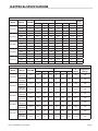
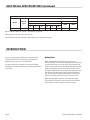
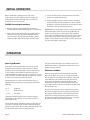
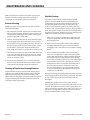
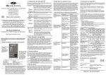
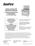
INSTALLATION AND
OPERATION MANUAL
GARLAND COUNTER TOP
HOT PLATES & GRIDDLES
MODELS: E24-12H, E24-24G,
E24-36G, E24-48G,
E24-60G & E24-72G
FOR YOUR SAFETY:
DO NOT STORE OR USE GASOLINE
OR OTHER FLAMMABLE VAPORS OR
LIQUIDS IN THE VICINITY OF
THIS OR ANY OTHER
APPLIANCE
WARNING:
IMPROPER INSTALLATION, ADJUSTMENT,
ALTERATION, SERVICE OR MAINTENANCE
CAN CAUSE PROPERTY DAMAGE, INJURY,
OR DEATH. READ THE INSTALLATION,
OPERATING AND MAINTENANCE
INSTRUCTIONS THOROUGHLY
BEFORE INSTALLING OR
SERVICING THIS EQUIPMENT
PLEASE READ ALL SECTIONS OF THIS MANUAL
AND RETAIN FOR FUTURE REFERENCE .
THIS PRODUCT HAS BEEN CERTIFIED AS
COMMERCIAL COOKING EQUIPMENT AND
MUST BE INSTALLED BY PROFESSIONAL
PERSONNEL AS SPECIFIED .
INSTALLATION AND ELECTRICAL CONNECTION
MUST COMPLY WITH CURRENT CODES:
IN CANADA - THE CANADIAN ELECTRICAL
CODE PART 1 AND / OR LOCAL CODES .
IN USA – THE NATIONAL ELECTRICAL CODE
ANSI / NFPA – CURRENT EDITION .
ENSURE ELECTRICAL SUPPLY CONFORMS WITH
ELECTRICAL CHARACTERISTICS SHOWN ON
THE RATING PLATE .
Users are cautioned that maintenance and repairs must be performed by a Garland authorized service agent
using genuine Garland replacement parts . Garland will have no obligation with respect to any product that has been
improperly installed, adjusted, operated or not maintained in accordance with national and local codes or installation
instructions provided with the product, or any product that has its serial number defaced, obliterated or removed,
or which has been modified or repaired using unauthorized parts or by unauthorized service agents .
For a list of authorized service agents, please refer to the Garland web site at http://www .garland-group .com .
The information contained herein, (including design and parts specifications), may be superseded and is subject
to change without notice .
GARLAND COMMERCIAL INDUSTRIES
185 East South Street
Freeland, Pennsylvania 18224
Phone: (570) 66-1000
Fax: (570) 66-90
Part##1009080
1009080Rev
Rev55(01/25/08)
(01/25/08)
Part
GARLAND COMMERCIAL RANGES, LTD .
1177 Kamato Road, Mississauga, Ontario L4W 1X4
CANADA
Phone: 905-624-0260
Fax: 905-624-5669
Enodis UK LTD .
Swallowfield Way, Hayes, Middlesex UB 1DQ ENGLAND
Telephone: 081-561-04
Fax: 081-848-0041
© 2004 Garland Commercial Industries,
Inc .1
Page
IMPORTANT INFORMATION
WARNING:
This product contains chemicals known to the state of california to cause cancer and/or birth defects
or other reproductive harm. Installation and servicing of this product could expose you to airborne
particles of glass wool/ceramic fibers. Inhalation of airborne particles of glass wool/ceramic fibers
is known to the state of California to cause cancer.
Page Part # 1009080 Rev 4 (01/25/08)
TABLE OF CONTENTS
IMPORTANT INFORMATION . . . . . . . . . . . . . . . . . . . . . . . . . . . . . . . . . . . . . . . . . 2
DIMENSIONS . . . . . . . . . . . . . . . . . . . . . . . . . . . . . . . . . . . . . . . . . . . . . . . . . . . . . . 4
ELECTRICAL SPECIFICATIONS . . . . . . . . . . . . . . . . . . . . . . . . . . . . . . . . . . . . . . . . 5
INTRODUCTION . . . . . . . . . . . . . . . . . . . . . . . . . . . . . . . . . . . . . . . . . . . . . . . . . . . . 6
Rating Plate. . . . . . . . . . . . . . . . . . . . . . . . . . . . . . . . . . . . . . . . . . . . . . . . . . . . . . . . . . . . . . . . . . . . . . 6
INSTALLATION . . . . . . . . . . . . . . . . . . . . . . . . . . . . . . . . . . . . . . . . . . . . . . . . . . . . . 7
Unpacking. . . . . . . . . . . . . . . . . . . . . . . . . . . . . . . . . . . . . . . . . . . . . . . . . . . . . . . . . . . . . . . . . . . . . . . 7
Leg Installation. . . . . . . . . . . . . . . . . . . . . . . . . . . . . . . . . . . . . . . . . . . . . . . . . . . . . . . . . . . . . . . . . . 7
Electrical Connections . . . . . . . . . . . . . . . . . . . . . . . . . . . . . . . . . . . . . . . . . . . . . . . . . . . . . . . . . . . 7
E24-12H Hot Plate. . . . . . . . . . . . . . . . . . . . . . . . . . . . . . . . . . . . . . . . . . . . . . . . . . . . . . . . . . . . . . . . 7
E24 Series Griddles. . . . . . . . . . . . . . . . . . . . . . . . . . . . . . . . . . . . . . . . . . . . . . . . . . . . . . . . . . . . . . . 7
INITIAL OPERATION . . . . . . . . . . . . . . . . . . . . . . . . . . . . . . . . . . . . . . . . . . . . . . . . . 8
Griddle Seasoning Instructions. . . . . . . . . . . . . . . . . . . . . . . . . . . . . . . . . . . . . . . . . . . . . . . . . . . 8
OPERATION . . . . . . . . . . . . . . . . . . . . . . . . . . . . . . . . . . . . . . . . . . . . . . . . . . . . . . . . 8
Open Type Burners . . . . . . . . . . . . . . . . . . . . . . . . . . . . . . . . . . . . . . . . . . . . . . . . . . . . . . . . . . . . . . 8
E24 Series Griddles. . . . . . . . . . . . . . . . . . . . . . . . . . . . . . . . . . . . . . . . . . . . . . . . . . . . . . . . . . . . . . . 8
Calibration of the Griddle Thermostat. . . . . . . . . . . . . . . . . . . . . . . . . . . . . . . . . . . . . . . . . . . . . 9
MAINTENANCE AND CLEANING . . . . . . . . . . . . . . . . . . . . . . . . . . . . . . . . . . . . 10
Exterior Cleaning . . . . . . . . . . . . . . . . . . . . . . . . . . . . . . . . . . . . . . . . . . . . . . . . . . . . . . . . . . . . . . . 10
Cleaning Of Top Surface Heating Elements. . . . . . . . . . . . . . . . . . . . . . . . . . . . . . . . . . . . . . . 10
Griddle Cleaning. . . . . . . . . . . . . . . . . . . . . . . . . . . . . . . . . . . . . . . . . . . . . . . . . . . . . . . . . . . . . . . . 10
Part # 1009080 Rev 5 (01/25/08)
Page DIMENSIONS
15"
[381mm]
29"
[737mm]
E24-12H
11-1/4"
[286mm]
REAR CABLE
ENTRANCE
2"
[51mm]
E24-24G, E24-36G, E24-48G E2460G and E24-72G
8-1/2"
[Ø216mm]
TYP
REAR CABLE
ENTRANCE
7"
[178mm]
23-1/4"
[591mm]
29-1/4"
[743mm]
4-1/8"
[105mm]
1-7/8"
[48mm]
GRIDDLE SUFFIX DEFINITIONS
72"
[1829mm]
60"
[1524mm]
48"
[1219mm]
36"
[914mm]
24"
[610mm]
12-13/16"
[325mm]
Add 4” (102mm) to height if sanitary legs are used
Page -24G
24 “ (610mm) Griddle
-36G
36” (914mm) Griddle
-48G
48” (1219 mm) Griddle
-60G
60” (1524 mm) Griddle
-72G
72” (1829 mm) Griddle
10-3/4"
[273mm]
15-3/8"
[391mm]
28-29/32"
[734mm]
Part # 1009080 Rev 4 (01/25/08)
ELECTRICAL SPECIFICATIONS
E24 Grill Loading Chart – Delta (Domestic Wiring)
Model
E24-24G
E24-36G
E24-48G
E24-60G
E24-72G
Total kW Load
Amps Per Phase
kW X-Y
kW Y-Z
KW X-Z
AX
AY
AZ
Single
Phase
8
0.0
4.0
4.0
19.2
19.2
33.3
38.5
240
8
0.0
4.0
4.0
16.7
16.7
28.9
33.3
480
8
0.0
4.0
4.0
8.3
8.3
14.4
16.7
208
12
4.0
4.0
4.0
33.3
33.3
33.3
57.7
240
12
4.0
4.0
4.0
28.9
28.9
28.9
50.0
480
12
4.0
4.0
4.0
14.4
14.4
14.4
25.0
208
16
4.0
4.0
8.0
50.9
33.3
50.9
76.9
240
16
4.0
4.0
8.0
44.1
28.9
44.1
66.7
480
16
4.0
4.0
8.0
22.0
14.4
22.0
33.3
208
20
4.0
8.0
8.0
50.9
50.9
66.6
96.2
240
20
4.0
8.0
8.0
44.1
44.1
57.7
83.3
480
20
4.0
8.0
8.0
22.0
22.0
28.9
41.7
208
24
8.0
8.0
8.0
66.6
66.6
66.6
115.4
240
24
8.0
8.0
8.0
57.7
57.7
57.7
100.0
480
24
8.0
8.0
8.0
28.9
28.9
28.9
50.0
Voltage
Total KW
208
E24 Grill Loading Chart – Export (wye)
Model
E24-24G
E24-36G
E24-48G
E24-60G
E24-72G
Total kW Load
Amps Per Phase
kW L1
kW L2
KW L3
AL1
AL2
AL3
A
1 Phase
8.0
4.0
4.0
0.0
16.7
16.7
0.0
33.3
240
380V 2N~
(220/380V)
6.7
3.4
3.4
0.0
15.3
15.3
0.0
30.5
220
415V 2N~
(240/415V)
12.0
4.0
4.0
4.0
16.7
16.7
16.7
50.0
240
380V 2N~
(220/380V)
10.1
3.4
3.4
3.4
15.3
15.3
15.3
45.8
220
415V 2N~
(240/415V
16.0
4.0
8.0
4.0
16.7
33.3
16.7
66.7
240
380V 2N~
(220/380V)
13.4
3.4
6.7
3.4
15.3
30.5
15.3
61.1
220
415V 2N~
(240/415V)
20.0
8.0
8.0
4.0
33.3
33.3
16.7
83.3
240
380V 2N~
(220/380V)
16.8
6.7
6.7
3.4
30.5
30.5
15.3
76.4
220
415V 2N~
(240/415V)
24.0
8.0
8.0
8.0
33.3
33.3
33.3
100.0
240
380V 2N~
(220/380V)
20.2
6.7
6.7
6.7
30.5
30.5
30.5
91.6
220
Voltage
Total KW
415V 2N~
(240/415V)
Part # 1009080 Rev 5 (01/25/08)
Single Phase
Voltage
Page ELECTRICAL SPECIFICATIONS Continued
LOADING CHART E24-H Hot Plate
Nominal Amperes Per Line
Model
E24-12H
3 Phase
Total Kw
Load
4.2
240V
Single Phase
208V
X
Y
Z
X
Y
Z
15.2
8.8
8.8
17.5
10.1
10.1
240V
208V
17.5
20.2
Export voltage available on request – Specify wiring required
kW loadings are reduced on 220 volt systems.
Standard wiring 240 volt (220/240) or 208 volt (197/219) single or three phase
INTRODUCTION
Your new equipment should be given regular care and
maintenance. Periodic inspections by your dealer or a
qualified service agency are recommended.
This product has been certified as commercial cooking
equipment and must be installed by professional personnel
as specified.
Rating Plate
When corresponding with the factory or your local
authorized factory service center regarding service problems
or replacement parts, be sure to refer to the particular unit
by the correct model number (including the prefix and suffix
letters and numbers) and the warranty serial number. The
rating plate affixed to the unit contains this information. The
rating plate is located on the main back panel behind the
unit, on hot plates. For griddles the plate is located on the
grease drawer slide, remove the grease drawer to access.
Before attempting the electrical connection, the rating
pate should be checked to ensure that the unit’s electrical
characteristics and the supply characteristics agree.
Page Part # 1009080 Rev 4 (01/25/08)
INSTALLATION
Unpacking
1. Switch panel size
Unpack units carefully and provide the necessary space on
counter of back bar. All units must be installed following the
minimum back and side clearances stated on the tag affixed
to each individual unit. To insure proper field wiring size
check tag attached to the rear of the unit near knockout.
2. Overload protection
Leg Installation
1. All units are shipped with N.S.F. approved legs. These
legs must be installed to provide a minimum clearance
of 4” (102mm) between he counter top and bottom of
the appliance in order to meet the National Sanitation
Foundation requirements.
2. When using the legs described above, raise the front of
the appliance and screw the leg into the leg-retaining nut
provided at each corner of the appliance, repeat at each
rear.
3. The unit may be leveled by adjusting the legs. Use a spirit
level and level the appliance four (4) ways: across the
front and back; and down left and right edges.
NOTE: Griddles may not rest evenly on the appliance body if
the appliances are not leveled.
Electrical Connections
Before attempting the electrical connection, the rating
plate should be checked to ensure that the unit’s electrical
characteristics and the supply characteristics agree.
Installation of the wiring must be made in accordance with
UL 197 Commercial Electric Cooking Appliance Standards,
Local and/or National Electrical Code, and ANSI/NFPA 701990 and include.
Part # 1009080 Rev 5 (01/25/08)
3. Wire type
4. Wire size
5. Temperature limitations of the wires
6. Method of connection (Cable, Conduit, etc.)
The service line enters though the rear of the unit and is
to be connected to the terminal block. Input voltage and
phasing must match the unit’s voltage and phasing.
Visually check all electrical connections.
Energize the electrical connections.
NOTE: Appliances are not internally fused. They must be
connected to a suitable disconnect box in accordance with
local code.
E24-12H Hot Plate
Electrical connection to the terminal may be made though
the knockout on the main back. Front access is gained by
raising the rear surface element and removing bowl. The
terminal block shield is located toward the back lower left of
the unit.
E24 Series Griddles
The electrical connections may be made though the
knockout at the rear of the unit to the terminal block located
behind the terminal block shield.
Front access is gained by raising and propping the griddle
plate. The terminal block shield is toward the back and left
of the appliance. Remove the shield to expose the terminal
block. Make the necessary connection and replace the shield.
These appliances have no fusing.
Page INITIAL OPERATION
Before use allow the griddle plate to reach room
temperature. Clean the griddle surface thoroughly by
washing with hot water and mild soap to remove rust
preventative. Rinse and dry well.
Griddle Seasoning Instructions
1 Remove all factory applied protective material by
washing with hot water, mild detergent or soap solution.
2. Apply a thin coat of cooking oil to the griddle surface,
about one ounce per square foot of griddle surface.
Spread over the entire griddle surface with a cloth to
create a thin film. Wipe off any excess oil with a cloth.
3. Turn on all thermostats, some discoloration will occur
when heat is applied to the steel.
4. Heat the griddle slowly for 15 to 20 minutes, then wipe
away the oil. Repeat the procedure 2 to 3 times until the
griddle has a slick, mirror like finish. Do this until you have
reached the desired cooking temperature.
IMPORTANT: Do not attain 450° F (232° C) (on the thermostat
control) during the “break-in” period. The griddle will not
require re-seasoning if it is used properly, if the griddle is
over heated and product begins to stick to the surface it may
be necessary to repeat the seasoning process again. If the
griddle is cleaned with soap and water it will be necessary to
re-season the griddle surface again.
OPERATION
Open Type Burners
It should be pointed out that the open burners are not
designed or intended heavy-duty service. Use of large
stockpots will severely damage the surface elements and
is not normally covered under the warranty policy! It is
recommended that cooking utensils no larger than 10” (254
mm) in diameter and with a capacity no larger than 1 gallon
(3.79 liters) be used on the surface elements.
Infinite switches are used to control the front and rear
heating elements. Numbers on switch knobs provide the
following:
HI – 5
High Heat
5–3
Medium Heat
3 – LO
Low Heat
Setting the switches between these numbers will give
intermediate heats. Switches are reversible and may be
turned right or left.
Two (2) pilot indicator lamps are provided, one for each
heating unit and these will illuminate when heat is being
produced by the elements.
E24 Series Griddles
All E24 series griddles are thermostatically controlled
from 125° to 450°F (52° to 232° C). To operate, turn the
thermostats to desired temperature. Indicator lamps will
come “ON” and as the griddle areas reach the desired
temperature the indicator lamp will go “OFF”. As the
thermostats call for more heat, the indicator lamps will
come “ON” and will continue to cycle “OFF” and “ON” as the
thermostat operates.
Do not waste electricity or abuse equipment by leaving
thermostat at high temperature settings if not required.
Throughout all idling periods, set the thermostat to low
temperature settings to keep the griddle warm. Re-set
thermostat as required for periods of heavy use. Turn the
thermostat to “OFF” at end of daily operation.
Surface heating units should not be left on high heat if not
covered by a cooking utensil. Turn the switch to number 4
position or lower when units are idling. Failure to do this will
shorten the life of the surface heating elements.
Page Part # 1009080 Rev 4 (01/25/08)
OPERATION Continued
Calibration of the Griddle Thermostat
Equipped with commercial duty snap action electric
thermostats, these units are designed to open on
temperature rise. Field re-calibration is seldom necessary and
should not be resorted to unless experience with cooking
results definitely proves that the control is not maintaining
the temperature to which the dial is set.
NOTE: NO ATTEMPT TO RECALIBRATE THE GRIDDLE CONTROL
SHOULD BE MADE WITHIN THE WARRANTY PERIOD. IF
THE CONTROL IS OUT ± 20° F FROM THE DIAL SETTING,
THE CONTROL WILL BE REPLACES UNDER WARRANTY.
IF SOMEONE ATTEMPTS RECALIBRATION DURING THE
WARRANTY PERIOD THERE WILL BE NO WARRANTY ON THE
CONTROL THAT WAS TAMPERED WITH.
4. Carefully remove the thermostat dial, not disturbing the
dial setting.
5. Hold the dial shaft steady and with a screwdriver turn the
calibration screw, (that is located inside the thermostat
shaft), clockwise to decrease and counter-clockwise to
increase the temperature. A 1/4 turn = 25°F change
6. Replace the thermostat dial and repeat steps 1 through 3
to verify if the correct adjustment has been made.
Dial Shaft
Calibration Screw Head
Calibration Instructions
1. Use a test instrument (surface pyrometer) with a special
disc type thermocouple or reliable “surface” type
thermometer. Note: A drop of oil on the face of the disc
will provide better contact with the griddle plate.
2. Turn all griddle thermostats to 350° F (177° C). In order
to allow the griddle temperature to stabilize the controls
must be allowed to cycle three times before taking a test
reading.
3. Check the temperature reading when the thermostat
cycles off by placing the sensor firmly on the center
of each section of the griddle surface. Take a second
temperature reading when they thermostat cycles back
on. Make a note of this reading. The average of the two
readings should be ± 20° of 350° set temperature.
If the average is more than the 20° tolerance, recalibrate
as follows.
Part # 1009080 Rev 5 (01/25/08)
Calibration
Screw Head
Increase
Decrease
1/4" Turn
Page MAINTENANCE AND CLEANING
NOTE: Disconnect line cord from the power supply or turn
the power off at the circuit breaker before cleaning of
servicing for your protection against electric shock.
Exterior Cleaning
Establish a regular cleaning schedule. Any spills should be
wiped off immediately.
1. Wipe exposed, cleanable surface when cool with a mild
detergent and hot water. Stubborn residue spots may be
removed with a lightweight non-metallic scouring pad.
Dry thoroughly with a clean cloth.
2. Stainless steel should be cleaned using a mild detergent,
a soft scouring pad and hot water. If it necessary to use a
non-metallic scouring pad, always rub in the direction of
the grain in the metal to prevent scratching. Use a water
based stainless steel cleaner (Dracket Twinkle), if you
want a high shine. Never use steel wool on Stainless steel.
3. The control panel surface is easily cleaned with hot water,
soap and a soft cloth. Do not use hard abrasives, solvent
type materials or metallic scouring pads since these will
scratch or cloud the surface.
4 Never spay the perforated areas or control panel with
steam or water, this will allow moisture into the control
cavity which could damage electrical components.
Cleaning Of Top Surface Heating Elements
Surface elements may be raised to permit removal of the
spillover burner bowl located under the surface elements.
Spillover burner bowls may be cleaned, wiped dry and
replaced. The Cooking top may be wiped with a damp cloth
using a mild detergent and warm water. Rinse with clear,
warm water and dry thoroughly.
Griddle Cleaning.
To produce evenly cooked, perfectly browned griddle
products, keep the griddle free from carbonized grease.
Carbonized grease on the surface hinders the transfer of
heat from the griddle surface to the food product. This
results in uneven browning and loss of cooking efficiency
and worst of all, carbonized grease tends to cling to griddle
foods, giving them a highly unsatisfactory and unappetizing
appearance. To keep the griddle clean and operating at peak
performance, follow these simple instructions.
1. After each use clean the griddle thoroughly with a grill
scraper or spatula. Wipe off any excess debris left from
the cooking process.
2. Once a day clean the griddle surface with a grill brick
and grill pad. Remove the grease container and clean
thoroughly, in the same manner as any ordinary cooking
utensil.
3. Once a week clean the griddle surface thoroughly. If
necessary, use a grill stone or grill pad over the griddle
surface. Rub with the grain of the metal while still warm.
A detergent may be used on the plate surface to help
clean it, but care must be taken to be sure it is thoroughly
removed. After removal of the detergent, the surface
of the plate should be covered with a thin film of oil to
prevent rusting. To remove discoloration, use a nonabrasive cleaner. Before re-using the griddle must be
re-seasoned. Keep the griddle drain tube to the grease
container clear at all times.
Empty grease trough below the griddle frequently. The front
grease trough should be washed using a hot, mild detergent
or soap solution. Rinse with clear, warm water and dry
thoroughly.
CAUTION: This griddle plate is steel, but the surface is
relatively soft and can be scored or dented by careless use of
a spatula. Be careful not to dent, scratch, or gorge the plate
surface. This will cause food to stick in those areas. Also, note,
since this is a steel griddle if a light coat of oil is not always
present, rust will develop on exposed area.
Page 10
Part # 1009080 Rev 4 (01/25/08)
Part # 1009080 Rev 5 (01/25/08)
Page 11