1
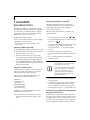
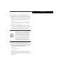
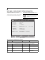
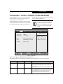
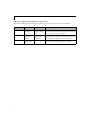
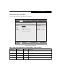
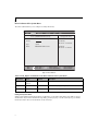
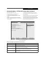
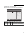
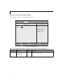
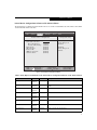
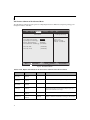
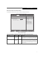
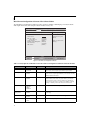
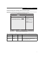
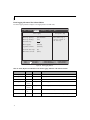
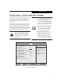
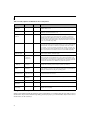
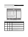
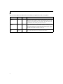
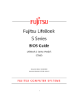
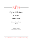
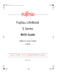
Fujitsu LifeBook
T Series
BIOS Guide
LifeBook T Series Model:
T5010
Document Date: 07/02/2008
Document Part Number: FPC58-1922-01
F U J I T S U C O M P U T E R S Y S T E M S C O R P O R AT I O N
1
LifeBook T Series BIOS
T Series BIOS
BIOS SETUP UTILITY
The BIOS Setup Utility is a program that sets up the
operating environment for your notebook. Your BIOS
is set at the factory for normal operating conditions,
therefore there is no need to set or change the BIOS
environment to operate your notebook.
The BIOS Setup Utility configures:
■
■
Device control feature parameters, such as changing
I/O addresses and boot devices.
System Data Security feature parameters, such
as passwords.
Entering the BIOS Setup Utility
To enter the BIOS Setup Utility, do the following (or use
the TrustedCore Menu, as detailed in the next section):
1. Turn on or restart your notebook.
2. Press [F2] once the Fujitsu logo appears on the
screen. This will open the main menu of the BIOS
Setup Utility with the current settings displayed.
3. Press the [RIGHT ARROW] or [LEFT ARROW] key
to scroll through the other setup menus to review or
alter the current settings.
Using the TrustedCore Menu
When the Fujitsu logo appears on the screen. press the
[Enter] key or click on the left mouse or touchpad
button; the TrustedCore Menu will appear.
The TrustedCore Menu provides shortcuts to the
following menus and information screens:
■
■
■
■
■
■
BIOS Setup
Diagnostic Screen
Boot Menu
Patent Information
System Information
Continue Booting
Navigating through the Setup Utility
The BIOS setup utility consists of six menus: Info,
System, Advanced, Security, Boot, and Exit. This document explains each menu in turn, including all
submenus and setup items.
The following procedures allow you to navigate the
setup utility menus:
], [
]
1. To select a menu, use the cursor keys: [
2. To select a field within a menu or a submenu, use the
cursor keys: [ ], [ ].
3. To select the different values for each field, press the
[Spacebar] or [+] to change to the next lower
selection and [F5] or [-] to go to the next higher
selection.
4. To activate a submenu press the [Enter] key.
5. To return to a menu from a submenu, press the [Esc]
key.
6. To go to the Exit menu from any other menu,
press the [Esc] key.
■
Selecting a field causes a help message
about that field to be displayed on the
right-hand side of the screen.
■
Pressing the Enter key with the highlight
on a selection that is not a submenu or
auto selection will cause a list of all
options for that item to be displayed.
Pressing the Enter key again will select
the highlighted choice.
7. Pressing the [F9] key resets all items in the BIOS to
the default values.
8. Pressing the [F10] key saves the current configuration and exits the BIOS Setup Utility. You will be
asked to verify this selection before it is executed.
9. Pressing the [F1] key gives you a general help screen.
Clicking on any of the fields will invoke the screen,
information, or action described.
Entering the Setup Utility After a Configuration
Change or System Failure
The Boot Menu can also be invoked by pressing the
[F12] key when the Fujitsu logo appears on the
screen.
If there has been a change in the system configuration
that does not agree with the parameter settings stored in
your BIOS memory, or there is a failure in the system,
the system beeps and/or displays an error message after
the Power On Self Test (POST). If the failure is not too
2
Info Menu
severe, it will give you an opportunity to modify the
setup utility settings, as described in the following steps:
1. When you turn on or restart the computer there is a
beep and/or the following message appears on the
screen:
Error message - please run SETUP
program Press <F1> key to continue,
<F2> to run SETUP
2. If an error message is displayed on the screen, and
you want to continue with the boot process and start
the operating system anyway, press the [F1] key.
■
If your notebook emits a series of beeps
that sounds like a code and the display is
blank, please refer to the Troubleshooting Section in the system User’s Guide.
The Troubleshooting Section includes a
list of error messages and their meanings.
■
If your data security settings require it,
you may be asked for a password before
the operating system will be opened.
3. If an error message is displayed on the screen, and
you want to enter the setup utility, press the [F2] key.
4. When the setup utility starts with a fault present, the
system displays the following message:
Warning!
Error message
[Continue]
5. Press any key to enter the setup utility. The system
will then display the Info Menu with current parameters values.
3
LifeBook T Series BIOS
INFO MENU - DISPLAYS BASIC SYSTEM INFORMATION
The Info Menu is a display only screen that provides the
configuration information for your notebook.
those fields. These fields are for information purposes
only, and cannot be modified by the user.
The following table shows the names of the menu fields
for the Info menu and the information displayed in
Info
System
The information, including CPU type and
speed, and total memory, displayed on this
screen varies according to the unit you
purchased.
Phoenix SecureCore(tm) Setup Utility
Advanced
Security
Boot
Exit
Product Name:
LifeBook T5010
Serial Number:
BIOS Version:
XXXXXXXX
1.0X (XX/XX/2008)
Processor Type:
L2 Cache:
Intel(R) Core(TM)2 Duo CPU
3072 KB
Total Memory:
Memory Slot 1:
Memory Slot 2:
2048 MB
1024 MB DDR3 SDRAM
1024 MB DDR3 SDRAM
Onboard MAC Address:
UUID:
XX-XX-XX-XX-XX-XX
00000000-0000-0000-0000-XXXXXXXXXXXX
Select Item
Select Menu
-/Space Change Values
Enter
Select Sub-Menu
▲
F1 Help
ESC Exit
P8400 @ 2.26GHz
F9
F10
Setup Defaults
Save and Exit
Figure 1. Info Menu
Table 1: Fields, Options and Defaults for the Info Menu
Menu Field
Default
Menu Field
Default
Note that all of the fields on this screen are display only and are for reference.
Note that the parameters listed may be different for your system, depending upon the system configuration.
4
Product Name:
LifeBook T5010
Total Memory:
2048 MB
Serial Number:
XXXXXXXX
Memory Slot 1:
1024 MB DDR2 SDRAM
BIOS Version:
1.0 (XX/XX/2008)
Memory Slot 2:
1024 MB DDR2 SDRAM
Processor Type:
Intel(R) Core(TM)2 Duo CPU P8400 @
2.26GHz
Onboard MAC Address:
XX-XX-XX-XX-XX-XX
L2 Cache:
3072 KB
UUID:
00000000-0000-0000-0000XXXXXXXXXXXX
System Menu
SYSTEM MENU – SETTING STANDARD SYSTEM PARAMETERS
The System Menu allows you to set or view the current
system parameters. (See Navigating through the Setup
Utility on page 2 for more information.)
the field’s function and any special information needed
to help understand the field’s use.
System Time and System Date can also be
set from your operating system without
using the setup utility. Use the Date and
Time icon on your Windows Control panel
or type time or date from the MS-DOS
prompt.
The following tables show the names of the menu fields
for the System menu and its submenus, all of the options
for each field, the default settings and a description of
Info
System
Phoenix SecureCore(tm) Setup Utility
Advanced
Security
Boot
Exit
Item Specific Help
System Time:
System Date:
[14:57:01]
[07/02/2008]
Adjust calendar clock.
▲ ▲
Drive0
Drive1
[Hitachi HTS542580K9SA00]
[MATSHITADVD-RAM UJ870BJ]
Language:
[English (US)]
Select Item
Select Menu
-/Space Change Values
Enter
Select Sub-Menu
▲
F1 Help
ESC Exit
<Tab>, <Shift-Tab>, or
<Enter> selects field.
F9
F10
Setup Defaults
Save and Exit
Figure 2. System Menu
Table 2: Fields, Options and Defaults for the System Menu
Note that the parameters listed in the following table may vary depending upon your system’s configuration.
Menu Field
Options
Default
Description
System Time:
–—
–—
Sets and displays the current time. Time is in a 24 hour format
of hours:minutes:seconds with 2 digits for each. (HH:MM:SS).
Example: 16:45:57. You may change each segment of the time
separately. Move between the segments with the [Tab] key and/or
[Shift] + [Tab] keys.
System Date:
–—
–—
Sets and displays the current date. Date is in a month/day/year
numeric format with 2 digits each for month and day and 4 digits for
year. (MM/DD/YYYY) for example: 03/20/2007. You may
change each segment of the date separately. Move between the
segments with the [Tab] key and/or [Shift] + [Tab] keys.
5
LifeBook T Series BIOS
Table 2: Fields, Options and Defaults for the System Menu
Note that the parameters listed in the following table may vary depending upon your system’s configuration.
Menu Field
Options
Default
Description
Drive0
Selects the Drive0
Serial ATA drive
submenu
The product
number of the hard
drive.
Display the type of device on this ATA/IDE interface. Pressing the
Enter key selects the Serial ATA Drive0 submenu allowing additional
device configuration options for this interface.
Drive1:
Selects the Drive1
Serial ATA drive
submenu
The product
number of the
optical drive.
Display the type of device on this ATA/IDE interface, if there is one.
Pressing the Enter key selects the Serial ATA Drive1 submenu allowing additional device configuration options for this interface.
Language:
■
[English (US)]
The default setting differs between the US/European and the
Japanese model. Selects the display language for the BIOS.
■
6
English (US)
Japanese (JP)
System Menu
Drive0 Submenu of the System Menu
The Drive0 submenu identifies what ATA devices are installed.
Info
System
Phoenix TrustedCore(tm) Setup Utility
Advanced
Security
Boot
Exit
Item Specific Help
Drive0 [Hitachi HTS542580K9SA00]
Drive0:
Type:
Model:
Capacity:
Hard Disk
Hitachi HTS542580K9SA00
80GB
(80,026,361,856 Bytes)
Select Item
Select Menu
[Enabled]
The drive is enabled.
-/Space Change Values
Enter
Select Sub-Menu
▲
F1 Help
ESC Exit
[Disabled]
The drive is disabled.
[Enabled]
F9 Setup Defaults
F10 Save and Exit
Figure 3. Drive0 Master Submenu
Table 3: Fields, Options and Defaults for the Drive0 Submenu of the System Menu
Menu Field
Options
Default
Description
Drive0:
■
[Enabled]
Allows you to enable or disable the hard drive 0.
■
Disabled
Enabled
Type:
---
---
Information only: Displays the type of hard disk installed as drive 0.
Model:
---
---
Information only: Displays the model of hard disk installed as drive 0.
Capacity
---
---
Information only: Displays the capacity of hard disk installed as drive 0.
7
LifeBook T Series BIOS
Drive1 Submenu of the System Menu
The Drive1 submenu allows you to configure secondary ATA devices.
Info
System
Phoenix SecureCore(tm) Setup Utility
Advanced
Security
Boot
Exit
Item Specific Help
Drive1 [MATSHITADVD-RAM UJ870BJ]
[Disabled]
The drive is disabled.
Drive1:
[Enabled]
Type:
Model:
CD/DVD
MATSHITADVD-RAM UJ870BJ
Select Item
Select Menu
-/Space Change Values
Enter
Select Sub-Menu
▲
F1 Help
ESC Exit
[Enabled]
The drive is enabled.
F9 Setup Defaults
F10 Save and Exit
Figure 4. Drive1 Submenu
Table 4: Fields, Options and Defaults for the Drive1 Submenu of the System Menu
Menu Field
Options
Default
Description
Drive1:
■
[Enabled]
Allows you to enable or disable the drive 1.
■
Disabled
Enabled
Type:
---
---
Information only: Displays the type of device installed as drive 1.
Model:
---
---
Information only: Displays the model of device installed as drive 1.
Exiting from System Menu
When you have finished setting the parameters on this menu, you can either exit from the setup utility, or move to
another menu. If you wish to exit from the setup utility, press the [Esc] key or use the cursor keys to go to the Exit
menu. If you wish to move to another menu, use the cursor keys.
8
System Menu
ADVANCED MENU – SETTING DEVICE FEATURE CONTROLS
The Advanced Menu allows you to:
■
■
■
■
■
Set the I/O addresses for the infrared port.
Set the keyboard and mouse features.
Select between the display panel and an external
display.
Enable or disable compensation for your display.
Enable or disable the IDE, Mouse, LAN, and Wireless
LAN controllers.
Info
Configure CPU and USB features in your system.
(See Navigating through the Setup Utility on page 2 for
more information.)
■
The following tables show the names of the menu fields
for the Advanced Menu and its submenus, all of the
options for each field, the default settings and a description of the field’s function and any special information
needed to help understand the field’s use.
Phoenix SecureCore(tm) Setup Utility
System
Advanced
Security
Boot
Exit
Item Specific Help
▲ ▲ ▲ ▲ ▲ ▲ ▲
Keyboard/Mouse Features
Video Features
Internal Device Configurations
CPU Features
USB Features
Miscellaneous Configurations
Intel(R) Active Management Technology
▲
Event Logging
Select Item
Select Menu
-/Space Change Values
Enter
Select Sub-Menu
▲
F1 Help
ESC Exit
Configures keyboard/
mouse features.
F9 Setup Defaults
F10 Save and Exit
Figure 5. Advanced Menu
Table 5: Fields, Options and Defaults for the Advanced Menu
Menu Field
Description
Keyboard/Mouse Features
When selected, opens the Keyboard/Mouse Features submenu, which allows setting external and
internal keyboard and mouse parameters.
Video Features
When selected, opens the Video Features submenu, which allows setting of the display parameters,
including routing of video signals to different displays.
Internal Device Configurations
When selected, opens the Internal Device Configuration submenu, which allows enabling or disabling the ATA, IDE, Bluetooth, Modem, LAN, and WLAN Controllers.
CPU Features
When selected, opens the CPU Features submenu to allow you to change the CPU speed for battery life optimization.
9
LifeBook T Series BIOS
Table 5: Fields, Options and Defaults for the Advanced Menu
Menu Field
Description
USB Features
When selected, opens the USB Features submenu to allow you to enable or disable legacy USB
devices and SCSI SubClass support.
Miscellaneous Configurations
When selected, opens the Miscellaneous Configurations submenu to allow you to enable or disable
the power button, Wake Up On LAN, and control volume settings.
Intel(R) Active Management
Technology
When selected, opens the Intel Active Management Technology submenu.
Event Logging
When selected, opens the event logging submenu.
10
Advanced Menu
Keyboard/Mouse Features Submenu of the Advanced Menu
The Keyboard/Mouse Features submenu is for setting the parameters of the integrated and external mouse and
keyboard.
Info
Phoenix SecureCore(tm) Setup Utility
Advanced
Security
Boot
Exit
System
Keyboard/Mouse Features
Numlock:
Item Specific Help
[On] or [Off]
Numlock is On or Off.
[Off]
[On/Padlock Off]
Numlock is On, but use
with [Fn] for 10-key
input.
* Windows XP or later
OS preserves Numlock
state when the user
logs off.
Select Item
Select Menu
-/Space Change Values
Enter
Select Sub-Menu
▲
F1 Help
ESC Exit
F9 Setup Defaults
F10 Save and Exit
Figure 6. Keyboard/Mouse Features Submenu
Table 6: Fields, Options and Defaults for the Keyboard/Mouse Submenu of the Advanced Menu
Menu Field
Options
Numlock:
■
■
■
On
Off
On/Padlock Off
Default
Description
[Off]
Sets the NumLock function state when the computer completes booting.
When [On] or [Off], Numlock is on or off. When [On/Padlock Off] is selected,
Numlock is on, but [Fn] key must be pressed used for 10-key input.
Windows XP (or later OS) preserves Numlock state when the user logs off.
11
LifeBook T Series BIOS
Video Features Submenu of the Advanced Menu
The Video Features submenu is for setting the display parameters.
Info
System
Phoenix SecureCore(tm) Setup Utility
Advanced
Security
Boot
Exit
Item Specific Help
Video Features
Display:
[Auto]
Select display terminal.
* This setting is not
effective after
operating system
starts up.
Select Item
Select Menu
-/Space Change Values
Enter
Select Sub-Menu
▲
F1 Help
ESC Exit
F9 Setup Defaults
F10 Save and Exit
Figure 7. Video Features Submenu
Table 7: Fields, Options and Defaults for the Video Features Submenu of the Advanced Menu
Menu Field
Options
Default
Description
Display:
■
[Auto]
Selects where the video signal will be routed. Note that this setting is
overridden after Windows starts up.
■
■
■
12
Internal Flat Panel
External (Analog)
External (Digital)
Auto
Advanced Menu
Internal Device Configurations Submenu of the Advanced Menu
The Internal Device Configuration submenu allows the user to enable or disable Bluetooth, LAN, Wireless LAN, IEEE
1394 and internal camera controllers.
Info
System
Phoenix SecureCore(tm) Setup Utility
Advanced
Security
Boot
Exit
Item Specific Help
Internal Device Configurations
Serial ATA Controller:
AHCI Configuration:
Intel(R) Turbo Memory:
Bluetooth(R):
LAN Controller:
Wireless LAN:
IEEE1394 Controller:
Internal Camera:
Select Item
Select Menu
[Enabled]
Serial ATA port is
enabled.
-/Space Change Values
Enter
Select Sub-Menu
▲
F1 Help
ESC Exit
[Disabled]
Serial ATA port is
disabled.
[Enabled]
[Enabled]
[Enabled]
[Enabled]
[Enabled]
[Enabled]
[Enabled]
[Enabled]
F9 Setup Defaults
F10 Save and Exit
Figure 8. Internal Device Configuration Submenu
Table 8: Fields, Options and Defaults for the Internal Device Configuration Submenu of the Advanced Menu
Menu Field
Options
Default
Description
Serial ATA Controller:
■
Disabled
Enabled
[Enabled]
Enables or disables the Serial ATA port.
Disabled
Enabled
[Enabled]
Enables or disables the selected Advanced Host Controller Interface
(AHCI).
Disabled
Enabled
[Enabled]
Enables or disables the Turbo Memory device.
Disabled
Enabled
[Enabled]
Enables or disables the Bluetooth device.
Disabled
Enabled
[Enabled]
Enables or disables the LAN controller.
Disabled
Enabled
[Enabled]
Enables or disables the Wireless LAN controller.
Disabled
Enabled
[Enabled]
Enables or disables the IEEE 1394 controller.
Disabled
Enabled
[Enabled]
Enables or disables the Internal Camera.
■
AHCI Configuration:
■
■
Intel(R) Turbo Memory:
■
■
Bluetooth:
■
■
LAN Controller:
■
■
Wireless LAN:
■
■
IEEE1394 Controller:
■
■
Internal Camera:
■
■
13
LifeBook T Series BIOS
CPU Features Submenu of the Advanced Menu
The CPU Features submenu provides options for configuring the Intel Core Multi-Processing and SpeedStep power
management features of the CPU.
Info
System
Phoenix SecureCore(tm) Setup Utility
Advanced
Security
Boot
Item Specific Help
CPU Features
Select Core
Multi-Processing
enabled or disabled.
[Enabled]
Core Multi-Processing:
SpeedStep(R) Technology: [Enabled]
XD Bit functionality:
[Enabled]
Virtualization Technology: [Disabled]
Intel(R) TXT:
Intel(R) VT-d:
[Disabled]
[Disabled]
Select Item
Select Menu
-/Space Change Values
Enter
Select Sub-Menu
▲
F1 Help
ESC Exit
Exit
F9 Setup Defaults
F10 Save and Exit
Figure 9. CPU Features Submenu
Table 9: Fields, Options and Defaults for the CPU Features Submenu of the Advanced Menu
Menu Field
Options
Default
Description
Core MultiProcessing:
■
Enabled
Disabled
[Enabled]
Enables or disables the Intel Core Multi-Processing features.
SpeedStep(R)
Technology:
■
Disabled
Enabled
[Enabled]
Enables or disables the SpeedStep(R) Technology features.
XD Bit
functionality:
■
Enabled
Disabled
[Enabled]
Enables or disables the Execute Disable Bit feature.
Virtualization
Technology:
■
Disabled
Enabled
[Disabled]
Enables or disables Virtualization Technology, an Intel technology
which includes hardware enhancements to improve upon software-based virtualization technologies.
Intel(R) TXT:
■
Disabled
Enabled
[Disabled]
Enables or disables the Trusted Execution Technology.
Disabled
Enabled
[Disabled]
Enables or disables the Virtualization Technology for Directed I/O.
■
■
■
■
■
Intel(R) VT-d:
■
■
14
Advanced Menu
USB Features Submenu of the Advanced Menu
The USB Features submenu provides options for enabling or disabling the USB devices.
Phoenix SecureCore(tm) Setup Utility
Info
System
Advanced
Security
Boot
Exit
USB Features
Legacy USB Support
SCSI SubClass Support:
Item Specific Help
[Disabled]
The feature is disabled.
[Enabled]
[Enabled]
[Enabled]
Legacy USB Emulation
is enabled and USB
devices are available
without USB aware OS.
Select Item
Select Menu
-/Space Change Values
Enter
Select Sub-Menu
▲
F1 Help
ESC Exit
F9 Setup Defaults
F10 Save and Exit
Figure 10. USB Features Submenu
Table 10: Fields, Options and Defaults for the USB Features Submenu of the Advanced Menu
Menu Field
Options
Legacy USB Support:
■
■
SCSI SubClass Support:
■
■
Default
Description
Disabled
Enabled
[Enabled]
When Enabled is selected, Legacy USB Emulation is enabled
and the USB devices are available without a USB-aware OS.
When Disabled is selected, Legacy USB support is disabled.
Disabled
Enabled
[Enabled]
When Enabled is selected, USB devices that belong to the
SCSI subclass in the mass storage class (e.g., USB Memory
Key) are enabled. Note that enabling this feature may cause
the system to hang during POST, depending on the device
that is connected.
15
LifeBook T Series BIOS
Miscellaneous Configurations Submenu of the Advanced Menu
The Miscellaneous Configurations submenu provides options for enabling or disabling the power button and the
Wake Up On LAN feature, and setting the volume and video memory size.
Info
System
Phoenix SecureCore(tm) Setup Utility
Advanced
Security
Boot
Exit
Miscellaneous Configurations
Power Button:
Wake up on LAN:
Force LAN Boot:
Volume Setting:
Hardware Power Management:
Low Power Mode:
FAN Control:
Select Item
Select Menu
Configures the power
button.
[Disabled]
[Disabled]
[Disabled]
[Middle]
[Enabled]
[Disabled]
[Normal]
*ACPI OS ignores this
setting.
-/Space Change Values
Enter
Select Sub-Menu
▲
F1 Help
ESC Exit
Item Specific Help
F9 Setup Defaults
F10 Save and Exit
Figure 11. Miscellaneous Configurations Submenu
Table 11: Fields, Options and Defaults for the Miscellaneous Configurations Submenu of Advanced Menu
Menu Field
Options
Default
Description
Power Button:
■
Disabled
Power Off
[Disabled]
Selecting Disabled disables the power button. Selecting Power Off
allows you to turn off system power with the power button.
Disabled
Enabled
[Disabled]
Enabled allows the system to wake up when the internal LAN
device receives a specific signal while in power-off state. Selecting
Disabled disables this feature.
Disabled
Enabled
[Disabled]
This feature is active only when “Wake up on LAN” is enabled.
When enabled, in the event of a system wake-up on LAN, the
system will try to first boot from the LAN before attempting to
boot from any other device, regardless of the BIOS boot priority
settings or disabling of the Preboot Execution Environment.
Off
Minimum
Middle
Maximum
[Middle]
Selects the initial volume setting for the system.
Disabled
Enabled
[Enabled]
Allows you to enable or disable the Hardware Power Management
technology.
Disabled
Enabled
[Disabled]
Enables and disables low power mode (Energy Star models).
Normal
Silent
[Normal]
Determines the operating noise level of the fan.
■
Wake up on LAN:
■
■
Force LAN Boot:
■
■
Volume Setting:
■
■
■
■
Hardware Power
Management:
■
Low Power Mode:
■
■
■
FAN Control:
■
■
16
Advanced Menu
Intel(R) Active Management Technology Submenu of the Advanced Menu
The Intel(R) Active Management Technology submenu provides options for enabling or disabling the Intel(R) Active
Management Technology and the Intel(R) Management Engine BIOS Extension screens.
Info
System
Phoenix SecureCore(tm) Setup Utility
Advanced
Security
Boot
Exit
Intel(R) Active Management Technology
Item Specific Help
[Disabled]
Active Management Technology:
Management Engine BIOS Extensions: [Disabled]
[Disabled]
Disables Intel(R) Active
Management Technology.
[Enabled]
Enables Intel(R) Active
Management Technology.
Select Item
Select Menu
-/Space Change Values
Enter
Select Sub-Menu
▲
F1 Help
ESC Exit
F9 Setup Defaults
F10 Save and Exit
Figure 12. Miscellaneous Configurations Submenu
Table 12: Fields, Options and Defaults for the Miscellaneous Configurations Submenu of Advanced Menu
Menu Field
Options
Default
Description
Active Management
Technology:
■
Disabled
Enabled
[Disabled]
Enables or disables the Intel(R) Active Management Technology.
Management Engine
BIOS Extensions:
■
Disabled
Enabled
[Disabled]
When disabled, the Intel(R) Management Engine BIOS Extensions
screens are not displayed. When enabled, the screens are
displayed. This feature can be selected only when Active
Management Technology is enabled.
■
■
17
LifeBook T Series BIOS
Event Logging Submenu of the Advanced Menu
The Event Logging submenu configures event logging features for DMI events.
Info
System
Phoenix SecureCore(tm) Setup Utility
Advanced
Security
Boot
Exit
Event Logging
Item Specific Help
Event Log Capacity:
Event Log Validity:
Space Available
Valid
View Event Log:
[Enter]
Event Logging:
System Boot Event:
[Enabled]
[Disabled]
Clear All Event Logs:
[No]
Mark Events as Read:
[Enter]
Select Item
Select Menu
-/Space Change Values
Enter
Select Sub-Menu
▲
F1 Help
ESC Exit
Press <Enter> key to
view the contents of
the event log.
F9 Setup Defaults
F10 Save and Exit
Figure 13. Event Logging Submenu
Table 13: Fields, Options and Defaults for the Event Logging Submenu of the Advanced Menu
Menu Field
Options
Default
Description
Event Log Capacity:
Space Available
Display only
Event Log Validity:
Valid
Display only
View Event Log:
■
Enter
[Enter]
Allows you to view content of event log
Event Logging:
■
Disabled
Enabled
[Enabled]
Turns event logging on and off for all DMI events.
Disabled
Enabled
[Disabled]
Turns event logging on and off for DMI system boot events.
No
Yes
[No]
When set to [Yes] all event logs will be cleared at next boot.
Enter
[Enter]
Lets you mark all events currently in the event log as having been read.
■
System Boot Event:
■
■
Clear All Event Logs:
■
■
Mark Events as Read:
18
■
Security Menu
SECURITY MENU – SETTING THE SECURITY FEATURES
The Security menu allows you to set up the data security
features of your notebook to fit your operating needs
and to view the current data security configuration. (See
Navigating through the Setup Utility on page 2 for more
information.)
The following tables show the names of the menu fields
for the Security Menu and its submenus, all the options
for each field, the default settings and a description of
the field's function and any special information needed
to help understand the field's use. The default condition
is no passwords required and no write protection.
Remember your passwords! If you set and
forget your User and Master hard disk
passwords, Fujitsu Computer Systems will
not be able to reset it. You may lose data
and have to replace your system board or
hard disk drive.
Info
System
■
Entering a password incorrectly 3 times in
a row causes the keyboard and mouse to
be locked out and the warning [System
Disabled] to be displayed. If this happens, restart the computer by turning off
and on the power with the power switch
and use the correct password on reboot.
■
If you make an error when re-entering
the password a Warning will display on
the screen. To try again press [Enter],
then retype the password. Press [Esc] to
abort the password setting process.
■
If the Security Panel on Resume is
Enabled and the Password on Boot is Disabled you will not have to type your
password upon resuming the system
from the Suspend or Save-to-Disk
modes. Power Management Security will
work only if Password boot is enabled.
Phoenix SecureCore(tm) Setup Utility
Advanced
Security
Boot
Exit
Item Specific Help
▲ ▲ ▲
Supervisor Password Is:
User Password Is:
Clear
Clear
Set Supervisor Password
Set User Password
Minimum User Password Length:
Password on Boot:
On Automatic Wake up:
KB Lock on Resume:
Boot from Removable Media:
Flash Write:
Hard Disk Security
Owner Information
TPM (Security Chip) Setting
[Enter]
[Enter]
[0]
[Disabled]
[Disabled]
[Disabled]
[All]
[Enabled]
Select Item
Select Menu
-/Space Change Values
Enter
Select Sub-Menu
▲
F1 Help
ESC Exit
Press <Enter> key to
set Supervisor Password
to enable any password
features.
Then password entry is
required to enter BIOS
Setup.
F9 Setup Defaults
F10 Save and Exit
Figure 14. Security Menu
19
LifeBook T Series BIOS
Table 14: Fields, Options and Defaults for the Security Menu
Menu Field
Options
Default
Description
Supervisor
Password is:
–—
Clear
A display-only field. Set is displayed when the system supervisor password is set
and Clear when it is not.
User Password is:
–—
Clear
A display-only field. Set is displayed when the general user
password is set, and Clear when it is not.
Set Supervisor
Password
–—
[Enter]
Sets, changes or cancels the Supervisor Password. The Supervisor Password may
be up to seven characters long and must include only letters or numbers (no
symbols). Passwords are NOT case-sensitive. To cancel a password press the
Enter key instead of entering characters in the Enter New Password field and in
the Re-enter New Password field. When a Supervisor Password is set it must be
used to access the BIOS setup utility.
Set User Password
–—
[Enter]
This field can only be accessed if the Supervisor Password is set. Sets, changes or
cancels the User Password. A User Password may be up to seven characters long
and must include only letters or numbers (no symbols). Passwords are NOT
case-sensitive. To cancel a password press [Enter] key instead of entering characters in the Enter New Password field and in the Re-enter New Password field.
When a User Password is set it must be used to access the BIOS setup utility.
Minimum User
Password Length:
–—
[0]
Supervisor can set password length (0 to 8) for user password. User cannot set a
password shorter than the minimum length.
Password on Boot:
■
Disabled
First Boot
Every Boot
[Disabled]
When set to First Boot, a password (User or Supervisor) is required just once
after the Power On Self Test (POST) before the operating system will be read
from a disk. When set to Every Boot, a password (User or Supervisor) is required
every time after the Power On Self Test (POST) before the operating system will
be read from a disk. When set to Disabled no password is required.
Disabled
Enabled
[Disabled]
When disabled, password entry is not required when the system wakes up automatically. When enabled, password entry is required upon wake up.
Disabled
Enabled
[Disabled]
When enabled, the PS/2 keyboard and mouse inputs are locked out upon
Resume until the password is entered. Note that this feature only works when a
password is entered before booting the operating system.
All
Supervisor only
[All]
Supervisor only allows access to boot the computer to removable media after
the Supervisor Password is entered.
Disabled
Enabled
[Enabled]
When disabled, the BIOS Flash memory will be write protected.
■
■
On Automatic
Wake up:
■
■
KB Lock on
Resume:
■
Boot from
Removable Media:
■
Flash Write:
■
■
■
■
Hard Disk Security:
–—
–—
Configures hard disk security features
Owner
Information:
–—
–—
Sets Owner information.
TPM (Security
Chip) Setting
___
___
Opens the Trusted Platform Module (TPM) Security Chip Setting submenu to
configure the Security Chip.
Exiting from the Security Menu
When you have finished setting the parameters on the Security Menu, you can either exit from setup utility or move to
another menu. If you wish to exit from setup utility, press the [Esc] key to go to the Exit Menu. If you wish to move to
another menu, use the cursor keys.
20
Security Menu
Hard Disk Security Submenu of the Security Menu
The Hard Disk Security submenu is for configuring hard disk security features.
Info
System
Phoenix SecureCore(tm) Setup Utility
Advanced
Security
Boot
Exit
Hard Disk Security
Item Specific Help
Drive0:
* Set Master Password
* Set User Password
Drive1:
Set Master Password
Set User Password
Clear
[Enter]
[Enter]
Not Available
[Enter]
[Enter]
Password Entry on Boot:
[Enabled]
* Hard Disk Password cannot be set or changed if
the system is rebooted from OS. Choose “Save
Changes and Power Off” in Exit Menu to shut
down the system, then Hard Disk Password
can be set or changed on next boot.
Select Item
Select Menu
-/Space Change Values
Enter
Select Sub-Menu
▲
F1 Help
ESC Exit
F9 Setup Defaults
F10 Save and Exit
Figure 15. Hard Disk Security Submenu
Table 15: Fields, Options and Defaults for the Hard Disk Security Submenu of the Security Menu
Menu Field
Options
Default
Description
Drive0:
___
Clear
Display-only. Default is Clear. When the Drive0 Password has been set, the field
changes to Set. When this password is set, the primary hard disk drive cannot be
used in another system unless the password is entered.
Set Master
Password
___
[Enter]
Sets, changes or cancels the Drive0 Master Password. The Drive0 Master Password
may be up to seven characters long and must include only letters or numbers (no
symbols). Passwords are NOT case-sensitive. When a Drive0 Password is set, it must
be used to access the hard drive if it is used in another system. Note that the password will not take effect until the system has been rebooted.
Set User
Password
___
[Enter]
Sets, changes or cancels the Drive0 User Password. The Drive0 User Password may
be up to seven characters long and must include only letters or numbers (no symbols). Passwords are NOT case-sensitive. When a Drive0 Password is set, it must be
used to access the hard drive if it is used in another system. Note that the password
will not take effect until the system has been rebooted.
Drive1:
___
Clear
Display-only. Default is Clear. When the Drive1 Password has been set, the field
changes to Set. When this password is set, the primary hard disk drive cannot be
used in another system unless the password is entered. When only one drive is
installed (Drive 0:), [Not available] appears here.
21
LifeBook T Series BIOS
Table 15: Fields, Options and Defaults for the Hard Disk Security Submenu of the Security Menu
Menu Field
Options
Default
Description
Set Master
Password
___
[Enter]
Sets, changes or cancels the Drive1 Master Password. The Drive10 Master Password
may be up to seven characters long and must include only letters or numbers (no
symbols). Passwords are NOT case-sensitive. When a Drive0 Password is set, it must
be used to access the hard drive if it is used in another system. Note that the password will not take effect until the system has been rebooted.
Set User
Password
___
[Enter]
Sets, changes or cancels the Drive1 User Password. The Drive1 User Password may
be up to seven characters long and must include only letters or numbers (no symbols). Passwords are NOT case-sensitive. When a Drive0 Password is set, it must be
used to access the hard drive if it is used in another system. Note that the password
will not take effect until the system has been rebooted.
Password Entry on
Boot:
■
[Enabled]
When set to disabled, entry of a Hard Disk Password is not required before OS boot.
(The hard disk is still password-protected without password entry.)
22
■
Disabled
Enabled
Security Menu
Owner Information Submenu of the Security Menu
The Owner Information submenu is for setting owner information. Note that the owner information cannot be set
without having entered a Supervisor Password.
Info
Phoenix SecureCore(tm) Setup Utility
Advanced
Security
Boot
Exit
System
Owner Information
Owner Information Is:
Clear
Set Owner Information
[Enter]
Foreground Color:
Background Color:
[Gray]
[Black]
Select Item
Select Menu
-/Space Change Values
Enter
Select Sub-Menu
▲
F1 Help
ESC Exit
Item Specific Help
F9 Setup Defaults
F10 Save and Exit
Figure 16. Owner Information Submenu
Table 16: Fields, Options and Defaults for the Owner Information Submenu of the Security Menu
Menu Field
Options
Default
Description
Owner Information
Is:
–—
Clear
Display only.
Set Owner Information:
–—
[Enter]
Field to write owner information, (i.e., name).
Foreground Color:
■
Light Cyan
Light Red
Light Magenta
Yellow
Bright White
[Gray]
Set foreground color.
Light Cyan
Light Red
Light Magenta
Yellow
Bright White
[Black]
Set background color.
■
■
■
■
■
Background Color:
■
■
■
■
■
■
Black
Blue
Green
Cyan
Red
Magenta
■
Black
Blue
Green
Cyan
Red
Magenta
■
■
■
■
■
■
■
■
■
Brown
White
Gray
Light Blue
Light Green
■
Brown
White
Gray
Light Blue
Light Green
■
■
■
■
■
■
■
■
■
23
LifeBook T Series BIOS
TPM (Security Chip) Setting Submenu of the Security Menu
The TPM (Security Chip) Setting submenu is used to enable or disabled the embedded security chip.
Info
Phoenix SecureCore(tm) Setup Utility
Advanced
Security
Boot
Exit
System
TPM (Security Chip) Setting
Item Specific Help
Security Chip:
[Enabled]
Current TPM State:
Change TPM State:
Clear Security Chip:
Disabled and Deactivated
[No Change]
[Enter]
Select Item
Select Menu
-/Space Change Values
Enter
Select Sub-Menu
▲
F1 Help
ESC Exit
F9 Setup Defaults
F10 Save and Exit
Figure 17. TPM (Security Chip) Setting Submenu
Table 17: Fields, Options and Defaults for TPM (Security Chip) Submenu of Security Menu
Menu Field
Options
Security Chip:
■
■
Current TPM State:
–—
Change TPM State:
■
Clear Security Chip
24
Disabled
Enabled
Default
Description
[Enabled]
Allows you to enable or disable the security chip. Note
that this is only active if a Supervisor Password has been
entered. A reboot is required after exit to configure the
Security Chip correctly. Clear Security Chip option
becomes selectable after reboot.
Disabled and Deactivated
Indicates the current state of the TPM chip.
No Change
Disable and
Deactivate
[No Change]
■
Allows you to enable or disable the TPM chip when the
Supervisor Password has been set.
■
Enter
[Enter]
Allows you to clear the Security Chip. Note that this does
not allow you to access already-encrypted data.
Security Menu
BOOT MENU – SELECTING THE OPERATING SYSTEM SOURCE
The Boot Menu is used to select the order in which the
BIOS searches sources for the operating system. Follow
the instructions for Navigating Through the Setup
Utility to make any changes. (See Navigating through the
Setup Utility on page 2 for more information.)
Info
System
The following tables show the names of the menu fields
for the Boot menu and its submenu, all of the options
for each field, the default settings and a description of
the field's function and any special information needed
to help understand the field's use.
Phoenix SecureCore(tm) Setup Utility
Advanced
Security
Boot
Exit
▲
[Disabled]
Boot Time Diagnostic Screen:
Boot Menu:
[Enabled]
Preboot Execution Environment: [Enabled]
Boot Device Priority
Item Specific Help
[Disabled]
Display the logo screen
during boot.
[Enabled]
Display the diagnostic
screen during boot.
Select Item -/Space Change Values
Select Sub-Menu
Select Menu Enter
▲
F1 Help
ESC Exit
F9 Setup Defaults
F10 Save and Exit
Figure 18. Boot Menu
Table 18: Fields, Options and Defaults for the Boot Menu
Menu Field
Options
Boot-time
Diagnostic Screen:
■
Boot Menu:
■
■
■
Preboot Execution
Environment:
■
Boot Device
Priority
—
■
Default
Description
Disabled
Enabled
[Disabled]
Turns on and off display of test results instead of Fujitsu logo screen
during Power On Self Test.
Disabled
Enabled
[Enabled]
When Disabled, the Boot Menu is disabled and the [F12] key is
ignored. When Enabled, the Boot Menu is enabled.
Disabled
Enabled
[Enabled]
Turns on and off the preboot execution environment feature.
—
This menu allows setting up the source for the operating system.
See “The Boot Device Priority Submenu” in the following section.
25
LifeBook T Series BIOS
Boot Device Priority Submenu of the Boot Menu
The Boot Device Priority submenu is for setting the order of checking of sources for the operating system.
■
Be careful of the operating environment when booting from a CD or you may overwrite files by mistake.
■
A bootable CD-ROM has either a floppy disk format or a hard drive format. When the CD-ROM is used,
drive allocations change automatically without changing the BIOS setup. If a floppy disk format is used,
the CD-ROM becomes Drive A. The CD-ROM will only take drive C: (hard drive format) if the internal
hard drive is not present or disabled. The bootable CD-ROM can never use a C: designation if a formatted
internal hard drive is present since the C: designator is always reserved for the hard drive.The boot
sequence ignores the new drive designations, but your application software will use the new designations.
Info
Phoenix SecureCore(tm) Setup Utility
System
Advanced
Security
Boot
Boot Device Priority
Item Specific Help
Boot priority order:
1: Floppy Disk Drive
2: Drive0 HDD: Hitachi HTS542580K9SA00
3: Drive1 HDD: None
4: CD/DVD Drive
5: NETWORK: Intel LAN
6:
7:
8:
Excluded from boot order:
: USB MEMORY: None
: USB HDD: None
: AMT: None
Select Item
Select Menu
-/Space Change Values
Enter
Select Sub-Menu
▲
F1 Help
ESC Exit
Exit
Keys used to view or
configure devices:
<+>/<Space> or <->
moves the device up or
down.
<x> exclude or include
the device to boot.
F9 Setup Defaults
F10 Save and Exit
Figure 19. Boot Device Priority Submenu
Table 19: Fields, Options and Defaults for the Boot Device Priority Submenu of the Boot Menu
Menu Field
Description
Boot priority order:
1: Floppy Disk Drive
2: Drive0:
3: Drive1:
4: CD/DVD Drive
5: NETWORK:
6:
7:
8:
Excluded from boot order:
: USB MEMORY:
: USB HDD:
: AMT:
The boot selections determine the order in which the BIOS searches for the operating system during a
startup sequence. To change the order, highlight one source by using the [up] or [down] cursor keys and
then press the [+] or [-] key to change the order number. Tapping [x] removes from the list a device that is
not installed. Tapping [x] on an item in the Excluded list adds the device to the Boot priority list. Be sure to
save your changed order when you exit the BIOS setup utility.
NOTE: Be aware that if you use the CD-ROM drive as the first boot device, certain files may be
overwritten, depending upon your operating environment.
Exiting from Boot Menu
When you have finished setting the boot parameters with the Boot Menu, you can either exit from the setup utility or
move to another menu. If you wish to exit from the setup utility press the [Esc] key to go to the Exit Menu. If you wish
to move to another menu, use the cursor keys.
26
Security Menu
EXIT MENU – LEAVING THE SETUP UTILITY
The Exit Menu is used to leave the setup utility. Follow
the instructions for Navigating Through the Setup
Utility to make any changes. (See Navigating through the
Setup Utility on page 2 for more information.)
Info
System
The following table shows the names of the menu fields
for the Exit menu, the default settings and a description
of the field's function and any special information
needed to help understand the field's use.
Phoenix TrustedCore(tm) Setup Utility
Advanced
Security
Boot
Exit
Item Specific Help
Exit Saving Changes
Exit Discarding Changes
Load Setup Defaults
Discard Changes
Save Changes
Save Changes and Power Off
Select Item
Select Menu
-/Space Change Values
Enter
Select Sub-Menu
▲
F1 Help
ESC Exit
Exit System Setup and
save your changes to
CMOS.
F9
F10
Setup Defaults
Save and Exit
Figure 20. Exit Menu
Table 20: Fields, Options and Defaults for the Exit Menu
Menu Field
Description
Exit Saving
Changes
Exit Saving Changes and Exit will store all the entries on every menu of the setup utility to the BIOS memory, then exit
the utility. A confirmation message Save Configuration changes and exit now? [Yes][No] is displayed.
Exit Discarding
Changes
Selecting Exit Discarding Changes and Exit will exit the setup utility with out writing to the BIOS memory. When the
BIOS recognizes this selection it will load the operating system and begin operation.
Load Setup
Defaults
Selecting Load Setup Defaults will load the factory preset default values for all menu fields, then display the message
Load default configuration now? [Yes] [No]. When confirmed the setup utility will return to the Exit
Menu. To return to another menu follow the directions in the Navigating Through the Setup Utility Section.
Discard
Changes
Selecting Discard Changes will load the previous values in BIOS memory for all menu fields. The message Load
previous configuration now? [Yes] [No] will be displayed. When confirmed the setup utility will return to
the Exit menu. To return to another menu, follow the directions in the Navigating Through the Setup Utility Section.
Save Changes
Selecting Save Changes will cause the new settings in all menus to be written to the BIOS memory. The message Save
configuration changes now? [Yes] [No] will be displayed. When confirmed, the setup utility will return to
the Exit menu. To return to another menu, follow the directions in the Navigating Through the Setup Utility section.
Save Changes
and Power Off
Selecting Save Changes and Power Off will cause the new settings in all menus to be written to the BIOS memory. The
message Save configuration changes and power off now? [Yes] [No] will be displayed. When confirmed, the system will shut down. If No is selected, the system will return to the Exit menu. To return to another menu,
follow the directions in the Navigating Through the Setup Utility section.
27