1
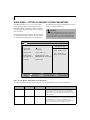
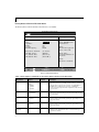
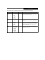
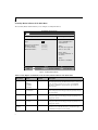
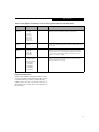
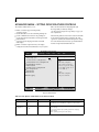
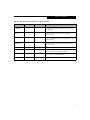
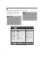
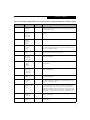
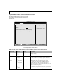
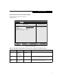
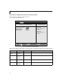
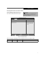
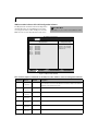
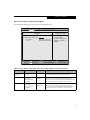
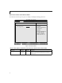
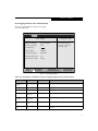
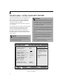
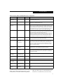
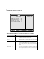
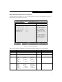
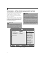
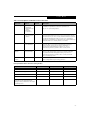
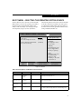
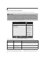
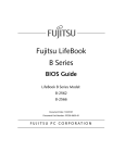
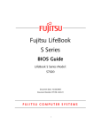
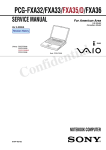
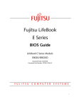
Fujitsu LifeBook
E Series
BIOS Guide
LifeBook E Series Models:
E-6664
E-6644
E-6634
E-6624
Document Date: 10/29/01
Document Part Number: FPC58-0629-01
F U J I T S U P C C O R P O R AT I O N
1
LifeBook E Series BIOS
E Series BIOS
BIOS SETUP UTILITY
The BIOS Setup Utility is a program that sets up the
operating environment for your notebook. Your BIOS
is set at the factory for normal operating conditions,
therefore there is no need to set or change the BIOS
environment to operate your notebook.
The BIOS Setup Utility configures:
■
■
Device control feature parameters, such as changing
I/O addresses and boot devices.
System Data Security feature parameters, such
as passwords.
Entering the BIOS Setup Utility
To enter the BIOS Setup Utility do the following:
1. Turn on or restart your notebook.
2. Press the [F2] key once the Fujitsu logo appears on
the screen. This will open the main menu of the
BIOS Setup Utility with the current settings
displayed.
3. Press the [RIGHT ARROW] or [LEFT ARROW] key
to scroll through the other setup menus to review or
alter the current settings.
Navigating Through The Setup Utility
The BIOS setup utility consists of seven menus: Main,
Advanced, Security, Power, Boot, Info, and Exit. This
document explains each menu in turn, including all
submenus and setup items.
The following procedures allow you to navigate the
setup utility menus:
], [
].
1. To select a menu, use the cursor keys:
2. To select a field within a menu or a submenu, use the
cursor keys: [ ], [ ].
3. To select the different values for each field, press the
[Spacebar] or [+] to change to the next higher
selection and [F5] or [-] to go to the next lower
selection.
4. To activate a submenu press the [Enter] key.
5. To return to a menu from a submenu, press
the [Esc] key.
2
6. To go to the Exit menu from any other menu,
press the [Esc] key.
P O I N TS
■
Selecting a field causes a help message about that
field to be displayed on the right-hand side of the
screen.
■
Pressing the Enter key with the highlight on a selection that is not a submenu or auto selection will cause
a list of all options for that item to be displayed.
Pressing the Enter key again will select the highlighted choice.
7. Pressing the [F9] key resets all items in the BIOS to
the default values.
8. Pressing the [F10] key saves the current configuration and exits the BIOS Setup Utility. You will be
asked to verify this selection before it is executed.
9. Pressing the [F1] key gives you a general help screen.
Entering the Setup Utility After a Configuration
Change or System Failure
If there has been a change in the system configuration
that does not agree with the parameter settings stored
in your BIOS memory, or there is a failure in the system,
the system beeps and/or displays an error message after
the Power On Self Test (POST). If the failure is not
too severe, it will give you the opportunity to modify
the settings of the setup utility, as described in the
following steps:
1. When you turn on or restart the computer there is a
beep and/or the following message appears on the
screen:
Error message - please run SETUP
program Press <F1> key to continue,
<F2> to run SETUP
2. If an error message is displayed on the screen, and
you want to continue with the boot process and start
the operating system anyway, press the [F1] key.
Main Menu
POINTS
■
If your notebook emits a series of beeps that sounds
like a code and the display is blank, please refer to the
Troubleshooting Section. The Troubleshooting Section
includes a list of error messages and their meanings.
■
If your data security settings require it, you may be
asked for a password before the operating system will
be opened.
3. If an error message is displayed on the screen, and
you want to enter the setup utility, press the [F2] key.
4. When the setup utility starts with a fault present, the
system displays the following message:
Warning!
Error message
[Continue]
5. Press any key to enter the setup utility. The system
will then display the Main Menu with current
parameters values.
3
LifeBook E Series BIOS
MAIN MENU – SETTING STANDARD SYSTEM PARAMETERS
The Main Menu allows you to set or view the current
system parameters. Follow the instructions for Navigating Through The Setup Utility to make any changes.
(See Navigating Through The Setup Utility on page 2 for
more information.)
the field’s function and any special information needed
to help understand the field’s use.
POINT
System Time and System Date can also be set from your
operating system without using the setup utility. Use
the calendar and time icon on your Windows Control
panel or type time or date from the MS-DOS prompt.
The following tables show the names of the menu fields
for the Main menu and its submenus, all of the options
for each field, the default settings and a description of
Main
Advanced
PhoenixBIOS Setup Utility
Security
Power
Boot
Info
Exit
Item Specific Help
System Time:
System Date:
[14:57:01]
[10/26/2001]
Floppy Disk A:
[1.44/1.2 MB 3.5"]
Primary Master
Secondary Master
[HITACHI_DK23CA-30-(PM)]
[MATSHITADVD-ROM SR-8175-SM)]
Language:
[English (US)]
Adjust calendar clock.
▲ ▲
Select Item
Select Menu
-/Space Change Values
Enter
Select Sub-Menu
▲
F1 Help
ESC Exit
<Tab>, <Shift-Tab>, or
<Enter> selects field.
F9
F10
Setup Defaults
Save and Exit
Figure 1. Main Menu
Table 1: Fields, Options and Defaults for the Main Menu
Note that the parameters listed in the following table may vary depending upon your system’s configuration.
4
Menu Field
Options
Default
Description
System Time:
–—
–—
Sets and displays the current time. Time is in a 24 hour format
of hours:minutes:seconds with 2 digits for each. (HH:MM:SS).
Example: 16:45:57. You may change each segment of the time
separately. Move between the segments with the [Tab] key and/or
[Shift] + [Tab] keys.
System Date:
–—
–—
Sets and displays the current date. Date is in a month/day/year
numeric format with 2 digits each for month and day and 4 digits for
year. (MM/DD/YYYY) for example: 03/20/1998. You may
change each segment of the date separately. Move between the
segments with the [Tab] key and/or [Shift] + [Tab] keys.
Main Menu
Table 1: Fields, Options and Defaults for the Main Menu
Note that the parameters listed in the following table may vary depending upon your system’s configuration.
Menu Field
Options
Default
Description
Floppy Disk A:
■
Disabled
1.44/1.2 MB
3.5"
[1.44/1.25 MB
3.5"]
Sets the format for floppy disk drive A if it is installed.
■
Primary Master:
■
Selects Primary
Master submenu
The product
number of the hard
drive.
Display the type of device on this ATA/ATAPI interface, if there is
one. Pressing the Enter key selects the Primary Master submenu
allowing additional device configuration options for this interface.
Secondary Master
■
Selects Secondary
Master submenu
The product number of the
CD-ROM drive.
Display the type of device on this ATA/ATAPI interface, if there is
one. Pressing the Enter key selects the Secondary Master submenu
allowing additional device configuration options for this interface
Language:
■
English (US)
Japanese (JP)
[English (US)]
The default setting differs between the US/European and the
Japanese model. Selects the display language for the BIOS.
■
5
LifeBook E Series BIOS
Primary Master Submenu of the Main Menu
The Primary Master submenu identifies what ATA devices are installed.
PhoenixBIOS Setup Utility
Main
Primary Master [HITACHI_DK23CA-30-(PM)]
Type:
Cylinders:
Heads:
Sectors:
Maximum Capacity:
[Hard Disk]to]
[16383]
[16]
[63]
8455MB
Multi-Sector Transfers:
LBA Mode Control:
PIO Transfer Mode:
DMA Transfer Mode:
[16 Sectors]
[Enabled]
[Fast PIO 4]
[Ultra DMA 5]
Item Specific Help
Select ATA/ATAPI drive
installed here.
[Auto]
The BIOS auto-types the
drive on boot time.
Except [Auto]
You enter parameters of
the drive.
[None]
The drive is disabled.
Select Item
Select Menu
-/Space Change Values
Enter
Select Sub-Menu
▲
F1 Help
ESC Exit
F9 Setup Defaults
F10 Save and Exit
Figure 2. Primary Master Submenu
Table 2: Fields, Options and Defaults for the Primary Master Submenu of the Main Menu
Menu Field
Options
Default
Description
Type:
■
Auto
None
CD-ROM
SuperDisk
Hard Disk
[Auto]
Selects the ATA/ATAPI device type. Select Auto to have the type
automatically identified by the BIOS at POST. If None is selected, all
of the following Set-up items do not appear. Select CD-ROM if a
CD-ROM drive is installed at this connection. If Hard Disk is
selected, you must specify the number of Cylinders, Heads, and Sectors for the drive.
■
■
■
■
6
Cylinders:
■
A number between
0 and 65,535
–—
This item is active only when Hard Disk is selected as the type. This
field is changed by incrementing (pressing the [Spacebar]) or by typing in the number.
Heads:
■
A number between
1 and 16
–—
This item is active only when Hard Disk is selected as type. You can
change the value by incrementing (pressing the [Spacebar]) or by
typing in the number.
Sectors:
■
A number between
0 and 63
–—
This item is active only when Hard Disk is selected as type. You can
change the value by incrementing (pressing the [Spacebar]) or by
typing in the number.
Maximum
Capacity:
■
Display only
–—
Displays the maximum capacity of the drive calculated from the
parameters of the hard disk when Auto is selected and the type
is identified as hard disk.
Main Menu
Table 2: Fields, Options and Defaults for the Primary Master Submenu of the Main Menu
Menu Field
Options
Multi-Sector
Transfers:
■
■
■
■
■
■
■
■
LBA Mode Control:
■
■
PIO Transfer Mode:
■
■
■
■
■
DMA Transfer
Mode:
■
■
■
■
■
■
■
■
■
Default
Description
Disabled
2 Sectors
4 Sectors
8 Sectors
16 Sectors
32 Sectors
64 Sectors
128 Sectors
[16 Sectors]
This option cannot be changed when Auto is selected. Specify the
number of sectors per block for multiple sector transfer. MAX refers
to the size the disk returns when required.
Disabled
Enabled
[Enabled]
Enables or disables logical Block Addressing in place of Cylinder,
Head, Sector addressing. This option cannot be changed when Auto
is selected.
Standard
Fast PIO 1
Fast PIO 2
Fast PIO 3
Fast PIO 4
[Fast PI0 4]
Selects the method for moving data to/from the drive. Autotype the
drive to select the optimum transfer mode. This option cannot be
changed when Auto is selected. Multi-word DMA is automatically
set to mode 1 for Fast PIO 1, Fast PIO 2, Fast PIO 3, and set to
mode 2 for Fast PIO 4 / DMA.
Disabled
Multiword DMA 1
Multiword DMA 2
Ultra DMA 0
Ultra DMA 1
Ultra DMA 2
Ultra DMA 3
Ultra DMA 4
Ultra DMA 5
[Ultra DMA 5]
Selects the method for moving data to/from the drive. Autotype the
drive to select the optimum transfer mode. This option cannot be
changed when Auto is selected.
7
LifeBook E Series BIOS
Secondary Master Submenu of the Main Menu
The Secondary Master submenu allows you to configure secondary ATA devices.
PhoenixBIOS Setup Utility
Main
Secondary Master [MATSHITADVD-ROM SR-8175-(SM)]
Type:
[Auto]
Multi-Sector Transfers:
LBA Mode Control:
PIO Transfer Mode:
DMA Transfer Mode:
[Disabled]
[Disabled]
[Standard]
[Disabled]
Item Specific Help
Select ATA/ATAPI drive
installed here.
[Auto]
The BIOS auto-types the
drive on boot time.
Except [Auto]
You enter parameters of
the drive.
[None]
The drive is disabled.
Select Item
Select Menu
-/Space Change Values
Enter
Select Sub-Menu
▲
F1 Help
ESC Exit
F9 Setup Defaults
F10 Save and Exit
Figure 3. Secondary Master Submenu
Table 3: Fields, Options and Defaults for the Secondary Master Submenu of the Main Menu
Menu Field
Options
Default
Description
Type:
■
Auto
None
CD-ROM
SuperDisk
Hard Disk
[Auto]
Selects the ATA/ATAPI device type. Select Auto to have the type
automatically identified by the BIOS at POST. If None is selected, all
of the following Set-up items do not appear. Select CD-ROM,
SuperDisk or Hard Disk for appropriate drive type installed at
this connection.
■
■
■
■
8
Cylinders:
■
A number between
0 and 65,535
–—
This item appears only when Hard Disk is selected as the type. This
field is changed by incrementing (pressing the [Spacebar]) or by typing in the number.
Heads:
■
A number between
1 and 16
–—
This item appears only when Hard Disk is selected as type. You can
change the value by incrementing (pressing the [Spacebar]) or by
typing in the number.
Sectors:
■
A number between
0 and 63
–—
This item appears only when Hard Disk is selected as type. You can
change the value by incrementing (pressing the [Spacebar]) or by
typing in the number.
Maximum
Capacity:
■
Display only
–—
Displays the maximum capacity of the drive calculated from the
parameters of the hard disk when Auto is selected and the type
is identified as hard disk, or User is selected.
Main Menu
Table 3: Fields, Options and Defaults for the Secondary Master Submenu of the Main Menu
Menu Field
Options
Multi-Sector
Transfers:
■
■
■
■
■
■
■
■
LBA Mode
Control:
■
PIO Transfer
Mode:
■
■
■
■
■
■
DMA Transfer
Mode:
■
■
■
■
■
■
■
■
■
Default
Description
Disabled
2 Sectors
4 Sectors
8 Sectors
16 Sectors
32 Sectors
64 Sectors
128 Sectors
[Disabled]
This option cannot be changed when Auto is selected. Specify the
number of sectors per block for multiple sector transfer.
Disabled
Enabled
[Disabled]
Enables or disables Logical Block Addressing in place of Cylinder,
Head, Sector addressing. This option cannot be changed when Auto
is selected.
Standard
Fast PIO 1
Fast PIO 2
Fast PIO 3
Fast PIO 4
[Standard]
Selects the method for moving data to/from the drive. Autotype the
drive to select the optimum transfer mode. This option cannot be
changed when Auto is selected. Multi-word DMA is automatically
set to mode 1 for Fast PIO 1, Fast PIO 2, Fast PIO 3, and set to
mode 2 for Fast PIO 4 / DMA.
Disabled
Multiword DMA 1
Multiword DMA 2
Ultra DMA 0
Ultra DMA 1
Ultra DMA 2
Ultra DMA 3
Ultra DMA 4
Ultra DMA 5
[Disabled]
Selects the method for moving data to/from the drive. Autotype the
drive to select the optimum transfer mode. This option cannot be
changed when Auto is selected.
Exiting from Main Menu
When you have finished setting the parameters on this
menu, you can either exit from the setup utility, or move
to another menu. If you wish to exit from the setup
utility, press the [Esc] key or use the cursor keys to go to
the Exit menu. If you wish to move to another menu, use
the cursor keys.
9
LifeBook E Series BIOS
ADVANCED MENU – SETTING DEVICE FEATURE CONTROLS
The Advanced Menu allows you to:
■
■
■
■
■
■
■
Enable or disable support for Plug & Play
operating systems.
Set the I/O addresses for the serial and parallel ports.
Set the communication mode for the parallel port.
Set an audio function I/O address, interrupt level and
DMA channel.
Select between the display panel and an external
CRT display.
Enable or disable compensation for your display.
Configure PCI, CPU, and USB features in your system.
Main
Advanced
Follow the instructions for Navigating Through
the Setup Utility to make any changes.
(See Navigating Through The Setup Utility on page 2 for
more information.)
The following tables show the names of the menu fields
for the Advanced Menu and its submenus, all of the
options for each field, the default settings and a description of the field’s function and any special information
needed to help understand the field’s use.
PhoenixBIOS Setup Utility
Security
Power
Boot
Info
Exit
Item Specific Help
Plug & Play O/S:
Protected Device Configurations:
▲ ▲ ▲ ▲ ▲ ▲ ▲
Serial/Parallel Port Configurations
Keyboard/Mouse Features
Video Features
Internal Device Configurations
PCI Configurations
CPU Features
USB Features
▲
Event Logging
Select Item
Select Menu
[No]
The BIOS configures
also non-boot devices.
Select if you are using
a non-Plug & Play OS or
a non-ACPI OS.
[Yes]
The BIOS configures
only boot devices.
-/Space Change Values
Enter
Select Sub-Menu
▲
F1 Help
ESC Exit
[No]
[No]
F9 Setup Defaults
F10 Save and Exit
Figure 4. Advanced Menu
Table 4: Fields, Options and Defaults for the Advanced Menu
Menu Field
Options
Default
Description
Plug & Play O/S:
■
No
Yes
[No]
Select Yes if you are using a Plug & Play capable operating system.
Select No if you need the BIOS to configure non-boot devices.
No
Yes
[No]
No: allows Plug & Play operating system to change device
system settings.
Yes: prevents a Plug & Play operating system from changing
system settings.
*ACPI operating system ignores this setting.
■
Protected Device
Configuration:
10
■
■
Advanced Menu
Table 4: Fields, Options and Defaults for the Advanced Menu
Menu Field
Options
Default
Description
Serial/Parallel Port
Configurations
–—
–—
When selected, opens the Serial/Parallel Port Configurations submenu which allows the user to modify settings for serial, infrared
and parallel ports.
Keyboard/Mouse
Features
–—
–—
When selected, opens the Keyboard/Mouse Features submenu,
which allows setting external and internal keyboard and
mouse parameters.
Video Features
–—
–—
When selected, opens the Video Features submenu, which allows
setting of the display parameters, including routing of video signals
to different displays.
Internal Device
Configurations
–—
–—
When selected, opens the Internal Device Configuration submenu,
which allows enabling or disabling the Floppy Disk, IDE, Modem
and LAN Controllers.
PCI Configurations
–—
–—
When selected, opens additional menus to configure PCI devices.
CPU Features
–—
–—
When selected, opens the CPU Features submenu to allow you to
change the CPU speed for battery life optimization.
USB Features
___
___
When selected, opens the USB Features submenu to allow you to
enable or disable the USB Floppy Disk Drive.
Event Logging
–—
–—
When selected, opens the event logging submenu.
11
LifeBook E Series BIOS
Serial/Parallel Port Configuration Submenu of the Advanced Menu
The Serial/Parallel Port Configuration submenu
provides the ability to set the I/O addresses and
interrupt levels for the serial, infrared and parallel
ports of your notebook.
CAUTION
I/O addresses, DMA channels and Interrupt levels
can be entered in various ways, including via the BIOS
setup utility, the control software for the I/O device,
or the hardware. If any two ports or devices, serial or
parallel, have the same I/O address assigned your
notebook will not function normally. Please keep a
record of original settings before making any changes
in the event that a restoration is required. See your
hardware and software documentation as well as the
setup utility to determine settings, limitations, etc.
P O I N TS
■
To prevent IRQ and address conflicts, avoid changing
the default settings. If you must change the settings,
you can call 1-800-8FUJITSU for technical assistance.
■
If your notebook emits a series of beeps that sounds
like a code and the display is blank, please refer to the
Troubleshooting Section. The Troubleshooting Section
includes a list of error messages and their meanings.
■
All I/O addresses in Table 5 are in hexadecimal.
PhoenixBIOS Setup Utility
Advanced
Serial/Parallel Port Configurations
Serial port:
I/O Address:
Interrupt:
Infrared Port:
Mode:
I/O Address:
Interrupt:
I/O Address:
DMA Channel:
Parallel Port:
Mode:
I/O Address:
Interrupt:
[Enabled]
[3F8 - 3FF]
[IRQ 4]
[Enabled]
[FIR]
[2E8 - 2EF]
[IRQ 3]
[400-43F]
[DMA 3]
[Enabled]
[Bi-directional]
[378 - 37F]
[IRQ 7]
Select Item
Select Menu
[Disabled]
The port is disabled.
[Enabled]
The port is enabled
with user configuration.
[Auto]
The port is configured
depending on 'Plug &
Play OS' setting.
-/Space Change Values
Enter
Select Sub-Menu
▲
F1 Help
ESC Exit
Item Specific Help
F9 Setup Defaults
F10 Save and Exit
Figure 5. Serial/Parallel Port Configuration Submenu
12
Advanced Menu
Table 5: Fields, Options and Defaults for the Serial/Parallel Port Configuration Submenu of Advanced Menu
Menu Field
Options
Serial Port:
■
■
■
I/O Address:
■
■
■
■
Interrupt:
■
■
■
■
Infrared Port:
■
■
■
Mode:
■
■
I/O Address:
■
■
■
■
Interrupt:
■
■
■
■
I/O address:
■
■
■
■
DMA Channel:
■
■
Parallel Port:
■
■
■
Mode:
■
■
■
I/O address:
■
■
■
Interrupt:
■
■
Default
Description
Disabled
Enabled
Auto
[Enabled]
Configures the serial port using either no configuration (Disabled), a user
defined configuration (Enabled), or by allowing the BIOS or OS to choose
the configuration (Auto).
3F8 - 3FF
2F8 - 2FF
3E8 - 3EF
2E8 - 2EF
[3F8 - 3FF]
Allows user to set the serial port base I/O address when serial port is
Enabled.
IRQ 3
IRQ 4
IRQ 10
IRQ 11
[IRQ 4]
Allows user to set the serial port interrupt when serial port is Enabled.
Disabled
Enabled
Auto
[Enabled]
Configures the infrared port using either no configuration (Disabled), a
user defined configuration (Enabled), or by allowing the BIOS or OS to
choose the configuration (Auto).
IrDA
FIR
[FIR]
When the infrared port is enabled this option is available allowing
the user to set the mode for the infrared port.
3F8 - 3FF
2F8 - 2FF
3E8 - 3EF
2E8 - 2EF
[2E8 - 2EF]
Allows user to set the infrared port I/O address when the
infrared port is Enabled.
IRQ 3
IRQ 4
IRQ 10
IRQ 11
[IRQ 3]
Allows user to set the infrared port interrupt when the infrared
port is Enabled.
400 - 43F
480 - 4BF
500 - 53F
580 - 5BF
[400 - 43F]
Allows user to set the infrared port I/O address when the
infrared port is Enabled.
DMA 1
DMA 3
[DMA 3]
Allows user to set the infrared port DMA Channel when the
infrared port is Enabled.
Disabled
Enabled
Auto
[Enabled]
Configures the parallel port using either no configuration (Disabled), a
user defined configuration (Enabled), or by allowing the BIOS or OS to
choose the configuration (Auto).
Output Only
Bi-directional
ECP
[Bi-directional]
When the parallel port is enabled this option is available allowing the user
to set the parallel port mode. Bi-directional allows two-way transfer of
information between your notebook and a connected parallel device.
Output Only (Half Duplex) allows information to be transferred in only
one direction, from your notebook to the printer or similar device. ECP
Mode allows communication with the ECP class of parallel I/O devices.
378 - 37F
278 - 27F
3BC - 3BF
[378 - 37F]
Allows user to set the parallel port base I/O address when the
parallel port is Enabled.
IRQ 5
IRQ 7
[IRQ 7]
Allows user to set the parallel port interrupt when the parallel
port is Enabled.
13
LifeBook E Series BIOS
Keyboard/Mouse Features Submenu of the Advanced Menu
The Keyboard/Mouse Features submenu is for setting
the parameters of the integrated and external mouse
and keyboard.
Main
Advanced
PhoenixBIOS Setup Utility
Security
Power Savings
Exit
Item Specific Help
Keyboard/Mouse Features
Numlock:
[Auto]
Hot Plug:
[Enabled]
Internal Pointing Device: [Auto Disabled]
Infrared Mouse:
[Disabled]
Select Item
Select Menu
-/Space Change Values
Enter
Select Sub-Menu
▲
F1 Help
ESC Exit
Select power-on state
for Numlock.
F9 Setup Defaults
F10 Save and Exit
Figure 6. Keyboard/Mouse Features Submenu
Table 6: Fields, Options and Defaults for the Keyboard/Mouse Submenu of the Advanced Menu
Menu Field
Options
Numlock:
■
■
■
Hot Plug:
■
■
Internal Pointing
Device:
■
■
■
■
Infrared Mouse:
■
■
14
Default
Description
Auto
On
Off
[Auto]
Sets the NumLock function state when the computer
completes booting.
Disabled
Enabled
[Enabled]
Enables and disables the ability to plug a mouse or keyboard into
the PS/2 port and have it immediately recognized and activated.
Auto Disabled
Manual Setting
Always Enabled
Always Disabled
[Auto Disabled]
Sets the device controlling the mouse cursor on the screen.
Always Enabled makes the pointing device always enabled
whether there is an external mouse or not. Always Disabled makes
the pointing device always disabled. Auto Disabled disables the
internal pointing device when an external pointing device is
connected to the PS/2 port. Manual Setting allows the device to be
enabled or disabled using a Hot Key.
Disabled
Enabled
[Disabled]
If IR Mouse is enabled, the PS/2 mouse is disabled. If you want to
use the internal pointing device with the IR Mouse, you must select
Always Enabled in the Internal Pointing Device.
Advanced Menu
Video Features Submenu of the Advanced Menu
The Video Features Submenu is for setting the
display parameters.
Main
PhoenixBIOS Setup Utility
Security
Power Savings
Exit
Advanced
Video Features
Item Specific Help
Display:
Compensation:
[Internal Flat Panel]
[Disabled]
Primary Video Adapter:
[Auto]
Select Item
Select Menu
-/Space Change Values
Enter
Select Sub-Menu
▲
F1 Help
ESC Exit
Select display terminal.
F9 Setup Defaults
F10 Save and Exit
Figure 7. Video Features Submenu
Table 7: Fields, Options and Defaults for the Video Features Submenu of the Advanced Menu
Menu Field
Options
Default
Description
Display:
■
Internal
Flat Panel
External
Simultaneous
[Internal
Flat-Panel]
Selects where the video signal will be routed.
Disabled
Enabled
[Disabled]
Enables or disables compensation which controls spacing on the
display. When enabled, displays with less than pixel resolution
1024 x 768 or 800 x 600 will still cover the entire screen.
Auto
Internal
[Auto]
Auto uses external video on Docking stations if present.
Internal always uses the internal video adapter.
■
■
Compensation:
■
■
Primary Video
Adapter:
■
■
15
LifeBook E Series BIOS
Internal Device Configurations Submenu of the Advanced Menu
The Internal Device Configuration submenu allows the
user to configure other internal devices.
Main
Advanced
PhoenixBIOS Setup Utility
Security
Power Savings
Exit
Item Specific Help
Internal Device Configurations
Floppy Disk Controller:
IDE Controller:
Modem Controller:
LAN Controller:
[Enabled]
[Both]
[Enabled]
[Enabled]
[Disabled]
Floppy disk drive is
disabled.
[Enabled]
Floppy disk drive is
enabled.
Select Item
Select Menu
-/Space Change Values
Enter
Select Sub-Menu
▲
F1 Help
ESC Exit
F9 Setup Defaults
F10 Save and Exit
Figure 8. Internal Device Configuration Submenu
Table 8: Fields, Options and Defaults for the Internal Device Configuration Submenu of the Advanced Menu
Menu Field
Options
Default
Description
Floppy Disk
Controller:
■
Disabled
Enabled
[Enabled]
Enables or disables the Floppy Disk Drive.
IDE Controller:
■
Disabled
Primary
Secondary
Both
[Both]
Enables or disables selected IDE devices.
Disabled
Enabled
[Enabled]
Enables or disables Modem controller.
Disabled
Enabled
[Enabled]
Enable or disables the LAN controller.
■
■
■
■
Modem Controller
■
■
LAN Controller
■
■
16
Advanced Menu
PCI Configuration Submenu of the Advanced Menu
The PCI Configuration submenu allows the user to
reserve specific interrupts (IRQs) for legacy ISA devices,
and to enable or disable built in PCI device modules.
Main
Advanced
POINT
The BIOS setting for your communication device
is variable depending on your LifeBook E Series
Built-to-order configuration.
PhoenixBIOS Setup Utility
Security
Power Savings
Exit
Item Specific Help
PCI Configurations
▲
IRQ Reservation
Select Item
Select Menu
-/Space Change Values
Enter
Select Sub-Menu
▲
F1 Help
ESC Exit
Reserve specific IRQs
for use by legacy ISA
devices.
F9 Setup Defaults
F10 Save and Exit
Figure 9. PCI Configuration Submenu
Table 9: Fields, Options and Defaults for the PCI Configuration Submenu of the Advanced Menu
Menu Field
Options
Default
Description
IRQ Reservation
–—
–—
Reserve specific IRQs for use by legacy ISA devices.
17
LifeBook E Series BIOS
IRQ Reservation Submenu of the PCI Configuration Submenu
The IRQ Reservation submenu of the PCI Configuration
submenu allows the user to mark IRQs as reserved for
use by legacy ISA devices. When an IRQ is reserved, the
BIOS does not use it for embedded PCI or ISA devices.
Main
CAUTION
Only IRQ’s 9, 10, & 11 can be reserved without conflict.
PhoenixBIOS Setup Utility
Security
Power Savings
Exit
Advanced
Item Specific Help
IRQ Reservation
IRQ
IRQ
IRQ
IRQ
IRQ
IRQ
IRQ
3:
4:
5:
7:
9:
10:
11:
[Available]
[Available]
[Available]
[Available]
[Available]
[Available]
[Available]
Select Item
Select Menu
-/Space Change Values
Enter
Select Sub-Menu
▲
F1 Help
ESC Exit
Reserve the specified
IRQ for use by legacy
ISA devices.
F9 Setup Defaults
F10 Save and Exit
Figure 10. IRQ Reservation Submenu
Table 10: Fields, Options and Defaults for the IRQ Reservation Submenu of the PCI Configuration Submenu
Menu Field
Options
IRQ 3:
■
■
IRQ 4:
■
■
IRQ 5:
■
■
IRQ 7:
■
■
IRQ 9:
■
■
IRQ 10:
■
■
IRQ 11:
■
■
18
Default
Description
Available
Reserved
[Available]
Reserves IRQ 3. If Reserved is selected, the BIOS reserves IRQ 3 for use by legacy ISA
devices and does not use it for embedded PCI or ISA devices. IRQ 3 is removed from
IRQ bitmap in the PCI IRQ routing table.
Available
Reserved
[Available]
Reserves IRQ 4.
Available
Reserved
[Available]
Reserves IRQ 5.
Available
Reserved
[Available]
Reserves IRQ 7.
Available
Reserved
[Available]
Reserves IRQ 9.
Available
Reserved
[Available]
Reserves IRQ 10.
Available
Reserved
[Available]
Reserves IRQ 11.
Advanced Menu
CPU Features Submenu of the Advanced Menu
The CPU Features Submenu provides options for configuring the CPU.
Main
Advanced
PhoenixBIOS Setup Utility
Security
Power Savings
Exit
CPU Features
Item Specific Help
SpeedStep(TM) Technology: [Enabled]
On Battery:
[Battery Optimized]
On AC:
[Maximum Performance]
Select Enhanced
Intel(TM) SpeedStep(TM)
Technology enabled or
disabled.
Select Item
Select Menu
-/Space Change Values
Enter
Select Sub-Menu
▲
F1 Help
ESC Exit
F9 Setup Defaults
F10 Save and Exit
Figure 11. CPU Features Submenu
Table 11: Fields, Options and Defaults for the CPU Features Submenu of the Advanced Menu
Menu Field
Options
SpeedStep(TM)
Technology:
■
On Battery:
■
■
■
■
On AC:
■
■
■
Default
Description
Disabled
Enabled
[Enabled]
Enables or disables the SpeedStep(TM) Technology features.
When disabled, On Battery and On AC are disabled.
Maximum
Performance
Battery Optimized
Automatic
[Battery
Optimized]
When Automatic is selected, the CPU speed changes based upon
the power source change. When Maximum Performance is
selected, the CPU speed is maximized. When Battery Optimized is
selected, the CPU speed is optimized for battery operation.
Maximum
Performance
Battery Optimized
Automatic
[Maximum
Performance]
When Automatic is selected, the CPU speed changes based upon
the power source change. When Maximum Performance is
selected, the CPU speed is maximized. When Battery Optimized is
selected, the CPU speed is optimized for battery operation.
19
LifeBook E Series BIOS
USB Features Submenu of the Advanced Menu
The USB Features Submenu provides options for enabling or disabling the USB Floppy Disk Drive.
Main
PhoenixBIOS Setup Utility
Security
Power Savings
Exit
Advanced
Item Specific Help
USB Features
USB Floppy Disk:
[Disabled]
Legacy Floppy Emulation
is disabled.
[Disabled]
[Enabled]
Legacy Floppy Emulation
is enabled and USB
floppy is available
without USB aware OS.
Select Item
Select Menu
-/Space Change Values
Enter
Select Sub-Menu
▲
F1 Help
ESC Exit
F9 Setup Defaults
F10 Save and Exit
Figure 12. USB Features Submenu
Table 12: Fields, Options and Defaults for the USB Features Submenu of the Advanced Menu
Menu Field
Options
Default
Description
USB Floppy Disk:
■
[Disabled]
Enables or disables Legacy Floppy Emulation. When Enabled is
selected, the USB floppy disk is available without a USB-aware
operating system.
■
20
Disabled
Enabled
Advanced Menu
Event Logging Submenu of the Advanced Menu
The Event Logging Submenu configures event logging
features for DMI events.
Main
PhoenixBIOS Setup Utility
Security
Power Savings
Exit
Advanced
Item Specific Help
Event Logging
Event Log Capacity:
Event Log Validity:
Space Available
Valid
View Event Log:
[Enter]
Event Logging:
System Boot Event:
[Enabled]
[Disabled]
Clear All Event Logs:
[No]
Mark Events as Read:
[Enter]
Select Item
Select Menu
-/Space Change Values
Enter
Select Sub-Menu
▲
F1 Help
ESC Exit
Press <Enter> key to
view the contents of
the event log.
F9 Setup Defaults
F10 Save and Exit
Figure 13. Event Logging Submenu
Table 13: Fields, Options and Defaults for the Event Logging Submenu of the Advanced Menu
Menu Field
Options
Default
Description
Event Log
Capacity:
Space Available
Display only
Event Log Validity:
Valid
Display only
View Event Log:
■
Enter
[Enter]
Allows you to view content of event log
Event Logging:
■
Disabled
Enabled
[Enabled]
Turns event logging on and off for all DMI events.
Disabled
Enabled
[Disabled]
Turns event logging on and off for DMI system boot events.
No
Yes
[No]
When set to [Yes] all event logs will be cleared at next boot.
Enter
[Enter]
Allows you to mark all events currently in the event log as having
been read.
■
System Boot
Event:
■
■
Clear All Event
Logs:
■
Mark Events as
Read:
■
■
21
LifeBook E Series BIOS
SECURITY MENU – SETTING THE SECURITY FEATURES
The Security menu allows you to set up the data security
features of your notebook to fit your operating needs
and to view the current data security configuration.
Follow the instructions for Navigating Through the
Setup Utility to make any changes.
(See Navigating Through The Setup Utility on page 2 for
more information.)
The following tables show the names of the menu fields
for the Security menu and its submenus, all of the
options for each field, the default settings and a
description of the field’s function and any special
information needed to help understand the field’s use.
The default condition is no passwords required and no
write protection.
POINTS
■
Entering a password incorrectly 3 times in a row will
cause the keyboard and mouse to be locked out and
the warning [System Disabled] to be displayed.
If this happens restart the computer by turning off
and on the power with the power switch and use the
correct password on reboot.
■
If you make an error when re-entering the password
a [Warning] will be displayed on the screen. To try
again press the Enter key and then retype the password. Press the Esc key to abort the password setting
process.
■
If the Power Management Security is Enabled and the
Password on Boot is Disabled you will not have to
type your password upon resuming the system from
the Suspend or Save-to-Disk modes. Power Management Security will work only if Password boot is
enabled.
■
Boot sector protection must be set to [Normal] to
install or upgrade an operating system.
POINT
If you set a password, write it down and keep it in a
safe place. If you forget the password you will have to
contact your support representative to regain access to
your secured functions and data.
Main
Advanced
PhoenixBIOS Setup Utility
Security
Power
Boot
Info
Exit
Item Specific Help
▲ ▲
Supervisor Password Is:
User Password Is:
Clear
Clear
Set Supervisor Password
Set User Password
Minimum User Password Length:
Password on Boot:
Password on Unattended Boot:
Password on Resume:
Boot from Removable Media:
Floppy Disk Access:
Hard Disk Security
Owner Information
[Enter]
[Enter]
[0]
[Disabled]
[Disabled]
[Disabled]
[All]
[All]
Hard Disk Boot Sector
Security Panel on Resume
[Normal]
[Enabled]
Select Item
Select Menu
-/Space Change Values
Enter
Select Sub-Menu
▲
F1 Help
ESC Exit
Figure 14. Security Menu
22
Press <Enter> key to
set Supervisor Password
to enable any password
features.
Then password entry is
required to enter BIOS
Setup.
F9 Setup Defaults
F10 Save and Exit
Security Menu
Table 14: Fields, Options and Defaults for the Security Menu
Menu Field
Options
Default
Description
Supervisor
Password is:
–—
Clear
A display-only field. Set is displayed when the system supervisor password
is set and Clear when it is not.
User Password is:
–—
Clear
A display-only field. Set is displayed when the general user
password is set, and Clear when it is not.
Set Supervisor
Password
–—
[Enter]
Sets, changes or cancels the Supervisor Password. Supervisor’s Password
may be up to seven characters long and must include only letters or numbers (no symbols). Passwords are NOT case- sensitive. To cancel a password press the Enter key instead of entering characters in the Enter New
Password field and in the Re-enter New Password field. When a Supervisor Password is set it must be used to access the BIOS setup utility.
Set User Password
–—
[Enter]
This field can only be accessed if the Supervisor Password is set. Sets,
changes or cancels the User Password. The User Password may be up to
seven characters long and must include only letters or
numbers (no symbols). Passwords are NOT case-sensitive. To cancel a
password press the Enter key instead of entering characters in the Enter
New Password field and in the Re-enter New Password field. When a
User Password is set it must be used to access the BIOS setup utility.
Minimum User
Password Length:
–—
[0]
Supervisor can set password length (0 to 8) for user password. User cannot set a password shorter than the minimum length.
Password on Boot:
■
Disabled
First Boot
Every Boot
[Disabled]
When set to First Boot, a password (User or Supervisor) is required just
once after the Power On Self Test (POST) before the operating system
will be read from a disk. When set to Every Boot, a password (User or
Supervisor) is required every time after the Power On Self Test (POST)
before the operating system will be read from a disk. When set to Disabled no password is required.
Disabled
Enabled
[Disabled]
When Enabled, a PS/2 keyboard and mouse are locked out when an
unattended boot occurs via LAN until a password is entered.
Disabled
Enabled
[Disabled]
When set to Enabled, a password (User or Supervisor) is required before
the operating system will resume. When set to Disabled no password is
required. If no Supervisor Password is set this feature is not available and
no password is required.
All
Supervisor only
[All]
Enable password allows supervisor access only.
All
Supervisor only
[All]
Enable password allows supervisor access only.
■
■
Password on
Unattended Boot
■
Password on
Resume:
■
Boot from Removable Media:
■
Floppy Disk Access:
■
■
■
■
■
Hard Disk Security:
–—
–—
Configures hard disk security features
Owner
Information:
–—
–—
Sets Owner information.
Hard Disk Boot
Sector:
■
Normal
Write Protected
[Normal]
Sets protection mode for hard disk drive.
Security Panel on
Resume
■
Disabled
Enabled
Enabled
Enables or disables the Security Panel feature upon Resume from Suspend.
■
■
Exiting from the Security Menu
When you have finished setting the parameters on the
Security Menu, you can either exit from setup utility or
move to another menu. If you wish to exit from setup
utility, press the Esc key to go to the Exit Menu. If you
wish to move to another menu, use the cursor keys.
23
LifeBook E Series BIOS
Hard Disk Security Submenu of the Security Menu
The Hard Disk Security Submenu is for configuring hard disk security features.
Main
Advanced
PhoenixBIOS Setup Utility
Security
Power Savings
Exit
Hard Disk Security
Primary Master Password Is:
Secondary Master Password Is:
Item Specific Help
Clear
Clear
Set Primary Master Password
[Enter]
Set Secondary Master Passwordz: [Enter]
Select Item
Select Menu
-/Space Change Values
Enter
Select Sub-Menu
▲
F1 Help
ESC Exit
F9 Setup Defaults
F10 Save and Exit
Figure 15. Hard Disk Security Submenu
Table 15: Fields, Options and Defaults for the Hard Disk Security Submenu of the Security Menu
Menu Field
Options
Default
Description
Primary Master
Password Is:
___
Clear
Display-only. Default is Clear. When the Primary Master Password has been set, the
field changes to Set. When this password is set, the primary hard disk drive cannot
be used in another system unless the password is entered.
Secondary Master
Password Is:
___
Clear
Display-only. Default is Clear. When Secondary Master Password has been set, the
field changes to Set. When this password is set, the secondary (modular) hard disk
drive cannot be used in another system unless the password is entered.
Set Primary
Master Password:
___
[Enter]
Sets, changes or cancels the Primary Master Password. The Primary Master Password may be up to seven characters long and must include only letters or numbers
(no symbols). Passwords are NOT case- sensitive. When a Primary Master Password is set, it must be used to access the primary hard drive if it is used in another
system. Note that the password will not take effect until the system has been
rebooted.
Set Secondary
Master Password:
___
[Enter]
Sets, changes or cancels the Secondary Master Password. The Secondary Master
Password may be up to seven characters long and must include only letters or numbers (no symbols). Passwords are NOT case- sensitive. When a Secondary Master
Password is set, it must be used to access the modular (secondary) hard drive if it is
used in another system. Note that the password will not take effect until the system
has been rebooted.
24
Security Menu
Owner Information Submenu of the Security Menu
The Owner Information Submenu is for setting owner information. Note that the owner information cannot be set
without having entered a Supervisor password.
Main
PhoenixBIOS Setup Utility
Security
Power Savings
Exit
Advanced
Owner Information
Owner Information Is:
Clear
Set Owner Information
[Enter]
Foreground Color:
Background Color:
[Gray]
[Black]
Item Specific Help
Press <Enter> key to
set owner information.
Up to 80 characters can
be set. Available
characters are ASCII
codes from 32 through
126.
The owner information
is always displayed at
the bottom line of the
screen during POST.
Select Item
Select Menu
-/Space Change Values
Enter
Select Sub-Menu
▲
F1 Help
ESC Exit
F9 Setup Defaults
F10 Save and Exit
Figure 16. Owner Information Submenu
Table 16: Fields, Options and Defaults for the Owner Information Submenu of the Security Menu
Menu Field
Options
Default
Description
Owner Information
Is:
–—
Clear
Display only.
Set Owner Information:
–—
[Enter]
Field to write owner information, (i.e., name).
Foreground Color:
■
Light Cyan
Light Red
Light Magenta
Yellow
Bright White
[Gray]
Set foreground color.
Light Cyan
Light Red
Light Magenta
Yellow
Bright White
[Black]
Set background color.
■
■
■
■
■
Background Color:
■
■
■
■
■
■
Black
Blue
Green
Cyan
Red
Magenta
■
Black
Blue
Green
Cyan
Red
Magenta
■
■
■
■
■
■
■
■
■
Brown
White
Gray
Light Blue
Light Green
■
Brown
White
Gray
Light Blue
Light Green
■
■
■
■
■
■
■
■
■
25
LifeBook E Series BIOS
POWER MENU – SETTING POWER MANAGEMENT FEATURES
The Power menu allows you to set and change the power
management parameters. Follow the instructions for
Navigating Through the Setup Utility to make any
changes. (See Navigating Through The Setup Utility on
page 2 for more information.)
The following tables show the names of the menu fields
for the Power menu and its submenus, all of the options
for each field, the default settings and a description of
the field’s function and any special information needed
to help understand the field’s use.
CAUTION
Resume on Modem ring when enabled will draw power
from the bridge battery alone when your system is
running off battery power. This could drain your bridge
battery. Disabling Resume on Modem ring or running
on AC power will prevent this from happening.
Main
Advanced
POINTS
■
In Windows 98 Auto-suspend Timeout, Hard Disk
Timeout, and Video Timeout features are available
exclusively through the operating system.
■
When resuming from a Save-to-Disk suspension there
will be a delay while the contents of system memory
and operating parameters are loaded from the hard
drive.
■
In Save-to-Disk mode there is no indication on the
Status Indicator to let you know you are suspended
rather than shut off from the power switch. You may
want to make a habit of always trying the Suspend/
Resume button before using the power switch.
PhoenixBIOS Setup Utility
Security
Power
Boot
Info
Exit
Item Specific Help
Power Savings:
Hard Disk Timeout:
Standby Timeout:
Auto Suspend Timeout:
[Customized]
[Off]
[4 Minutes]
[15 Minutes]
▲
Select Power Management
Mode. Choosing modes
changes system power
management settings.
Maximum Power Savings
conserves the greatest
amount of system power
while Maximum
Performance conserves
power but allows
greatest system
performance. To alter
these setting, choose
Customize. To turn off
power management,
choose Disabled.
Advanced Features
Select Item
Select Menu
-/Space Change Values
Enter
Select Sub-Menu
▲
F1 Help
ESC Exit
Figure 17. Power Menu
26
F9 Setup Defaults
F10 Save and Exit
Power Menu
Table 17: Fields, Options and Defaults for the Power Menu
Menu field
Options
Power Savings:
■
■
■
■
Hard Disk Timeout:
■
■
Standby Timeout:
■
■
Default
Description
Disabled
Customized
Maximum Power
Savings
Maximum
Performance
[Customized]
Sets the power savings parameters to a factory installed
combination of parameters, a custom set of parameters set
by you or no power saving features.
Off
30 seconds to 20
Minutes
[Off]
Sets the length of time that the hard drive can be inactive before your
notebook automatically turns off the power to the hard drive controller
and drive motor. If you choose a factory installed combination of parameters this field will display the setting. If you choose to customize the
parameters you will be able to set this yourself. The options available vary
from Off, which has no inactivity shutoff, to 20 minutes.
Off
1 to 16 Minutes
[4 Minutes]
Sets the length of time without any user input device activity
before the CPU is set to half speed and the display and the hard
drive are turned off. If you choose a factory combination of
parameters this field will display the setting. If you choose to
customize the parameters you will be able to set this yourself.
Off
5 to 60 minutes
[15 Minutes]
Sets the length of time without any I/O activity before your notebook goes into Suspend mode. If you choose a factory combination
of parameters this field will display that setting. If you choose to
customize the parameters you will be able to set this yourself. Off
has no inactivity suspension.
–—
When selected, opens the Advanced Features submenu which
allows setting additional power saving parameters.
Auto Suspend
Timeout:
■
Advanced
Features:
–—
■
Factory Installed Values for Power Saving Profiles
Hard Disk Timeout
Standby Timeout
Auto Suspend Timeout
Customized:
Off
4 Minutes
15 Minutes
Maximum Power Savings:
30 Seconds
1 Minute
5 Minutes
Maximum Performance:
Off
Off
15 Minutes
Disabled:
Off
Off
Off
Sample Customized Profile: (To get even better
battery life keep the display and volume
settings as low as possible and use the sample
customized profile.)
2 Minutes
1 Minute
5 Minutes
27
LifeBook E Series BIOS
Advanced Features Submenu of the Power Menu
The Advanced Features submenu is for setting some non-time related power saving parameters.
PhoenixBIOS Setup Utility
Power
Advanced Features
Suspend/Resume Switch:
Lid Closure Suspend:
Lid Open Resume:
Resume On LAN:
[Enabled]
[On]
[On]
[Off]
Auto Suspend on Undock:
[Disabled]
Select Item
Select Menu
Configures the
Suspend/Resume switch.
-/Space Change Values
Enter
Select Sub-Menu
▲
F1 Help
ESC Exit
Item Specific Help
F9 Setup Defaults
F10 Save and Exit
Figure 18. Advance Features Submenu
Table 18: Fields, Options and Defaults for the Advanced Features Submenu of the Power Menu
Menu Field
Options
Default
Description
Suspend/Resume
Switch:
■
Disabled
Enabled
[Enabled]
Sets the function of Suspend/Resume button when the notebook is in active state.
The resume function can not be disabled; it works regardless of any other settings.
Lid Closure
Suspend:
■
Off
On
[On]
Enables and disables having closure of the Display panel put your
notebook in Suspend mode.
Lid Open Resume:
■
Off
On
[On]
Enables or disables the system from resuming automatically when the lid is opened.
Off
On
[Off]
Enables and disables having LAN activity cause the system to
reactivate from inactivity timeouts.
Disabled
Auto
Always
Enabled
[Disabled]
When set to disable, your notebook will not automatically enter Suspend mode
when ejected from a docking station. When set to Auto, your notebook will automatically enter Suspend mode if your lid is closed when ejected. When set to
Always Enabled, your notebook will automatically enter Suspend mode when ejecting from a docking station.
■
■
■
Resume On LAN:
■
■
Auto Suspend on
Undock:
■
■
■
Exiting from Power Menu
When you have finished setting the boot parameters
with the Power menu, you can either exit from the setup
utility or move to another menu. If you wish to exit from
28
the setup utility press the Esc key to go to the Exit menu.
If you wish to move to another menu, use the cursor
keys.
Boot Menu
BOOT MENU – SELECTING THE OPERATING SYSTEM SOURCE
The Boot Menu is used to select the order in which the
BIOS searches sources for the operating system. Follow
the instructions for Navigating Through the Setup
Utility to make any changes. (See Navigating Through
The Setup Utility on page 2 for more information.)
Main
Advanced
The following tables show the names of the menu fields
for the Boot menu and its submenu, all of the options
for each field, the default settings and a description of
the field’s function and any special information needed
to help understand the field’s use.
PhoenixBIOS Setup Utility
Security
Power Savings
Boot
▲
Quick Boot:
Boot Time Diagnostic Screen:
[Enabled]
[Disabled]
Preboot Execution Environment:
Boot Device Priority
[Disabled]
Item Specific Help
[Disabled]
All diagnostic tests
will be done.
[Enabled]
Some diagnostic tests
may be skipped while
booting to speed up.
[Auto]
Diagnostic tests will
be automatically
skipped or done
according to the order
of the ACPI OS.
Select Item -/Space Change Values
Select Sub-Menu
Select Menu Enter
▲
F1 Help
ESC Exit
F9 Setup Defaults
F10 Save and Exit
Figure 19. Boot Menu
Table 19: Fields, Options and Defaults for the Boot Menu
Menu Field
Options
QuickBoot:
■
■
■
Boot-time
Diagnostic Screen:
■
Preboot Execution
Environment:
■
Boot Device
Priority
■
■
Default
Description
Disabled
Enabled
Auto
[Enabled]
Turns on and off booting with a truncated set of Power On Self Test.
(Fewer tests mean faster turn on.)
Disabled
Enabled
[Disabled]
Turns on and off display of test results instead of Fujitsu logo screen
during Power On Self Test.
Disabled
Enabled
[Disabled]
Turns on and off the preboot execution environment feature.
—
This menu allows setting up the source for the operating system.
See “The Boot Device Priority Submenu” in the following section.
29
LifeBook E Series BIOS
Boot Device Priority Submenu of the Boot Menu
The Boot Device Priority Submenu is for setting the order of checking of sources for the operating system.
CAUTIONS
■
■
Be careful of the operating environment when booting from a CD-ROM or you may overwrite files by mistake.
A bootable CD-ROM has either a floppy disk format or a hard drive format. When the bootable CD-ROM is used, the
drive allocations change automatically without changing the BIOS setup. If a floppy disk format is used, the CD-ROM
becomes Drive A. The CD-ROM will only take drive C: (hard drive format) if the internal hard drive is not present or
is disabled. The bootable CD-ROM can never use a C: designation if a formatted internal hard drive is present since
the C: designator is always reserved for the internal hard drive.The boot sequence ignores the new drive designations,
however, your application software will use the new designations.
Main
PhoenixBIOS Setup Utility
Security
Power Savings
Boot
Advanced
Boot Device Priority
Item Specific Help
Floppy Disk Drive
+Hard Disk Drive
ATAPI CD-ROM Drive
The top device has the
highest priority.
Select Item
Select Menu
-/Space Change Values
Enter
Select Sub-Menu
▲
F1 Help
ESC Exit
➞
➞
<Enter> expands or
collapses devices with
a + or -.
<Ctrl+Enter> expands
all.
< > or < > selects a
device.
<+>/<Space> or <->
moves the device up or
down.
<Shift+1> enables or
disables a device.
F9 Setup Defaults
F10 Save and Exit
Figure 20. Boot Device Priority Submenu
Table 20: Fields, Options and Defaults for the Boot Device Priority Submenu of the Boot Menu
Menu Field
Options
Description
Floppy Disk Drive
–—
The boot selections determine the order in which the BIOS searches for
the operating system during a startup sequence. To change the order
highlight one source by using the [up] or [down] cursor keys and then
press the [+] or [-] key to change the order number for that source. Be
sure to save your changed order when you exit the BIOS setup utility.
+Hard Disk Drive
■
–—
■
ATAPI CD-ROM Drive
HITACHI_DK23CA-30-(PM)
Bootable Add-in Cards
–—
Exiting from Boot Menu
When you have finished setting the boot parameters with
the Boot menu, you can either exit from the setup utility
30
–—
or move to another menu. If you wish to exit from the
setup utility press the Esc key to go to the Exit menu. If
you wish to move to another menu, use the cursor keys.
Info Menu
INFO MENU - DISPLAYS BASIC SYSTEM INFORMATION
The Info menu is a display only screens that provides the
configuration information for your notebook.
The following table shows the names of the menu fields
for the Info menu and the information displayed in
those fields. These fields are for information purposes
only, and cannot be modified by the user (except for the
Asset Number as in the Point below).
Main
Advanced
POINTS
■
■
The asset number is an optional user-entered field
and can be entered through the use of third party
DMI Compliant software, such as LANdesk Client
Manager.
The information, including CPU type and speed, and
total memory, displayed on this screen varies
according to the unit you purchased.
PhoenixBIOS Setup Utility
Security
Power Savings
Boot
Info
Item Specific Help
BIOS Version:
BIOS Date:
BIOS Area:
2.00
10/17/2001
E400h - FFFFh
CPU Type:
CPU Speed:
L1 Cache:
L2 Cache:
Pentium(R) III processor-M
1.2 GHz
32 KB
512 KB
Total Memory:
128 MB
Memory Slot 1: 128 MB SDRAM
Memory Slot 2: None
Select Item
Select Menu
-/Space Change Values
Enter
Select Sub-Menu
▲
F1 Help
ESC Exit
F9
F10
Setup Defaults
Save and Exit
Figure 21. Info Menu
Table 21: Fields, Options and Defaults for the Info Menu
Note that the parameters listed in the following table may be different, depending upon the system configuration.
Menu Field
Default
Menu Field
Default
BIOS Version:
2.00
L1 Cache:
32 KB
BIOS Date:
10/17/2001
L2 Cache:
512 KB
BIOS Area:
E400h – FFFFh
Total Memory:
128 MB
CPU Type:
Pentium(R) III processor-M
Memory Slot 1:
128 MB SDRAM
CPU Speed:
1.2 GHz
Memory Slot 2:
None
31
Exit Menu
LifeBook E Series BIOS
EXIT MENU – LEAVING THE SETUP UTILITY
The Exit Menu is used to leave the setup utility. Follow
the instructions for Navigating Through the Setup
Utility to make any changes. (See Navigating Through
The Setup Utility on page 2 for more information.)
Main
Advanced
The following table shows the names of the menu fields
for the Exit menu, the default settings and a description
of the field’s function and any special information
needed to help understand the field’s use.
PhoenixBIOS Setup Utility
Security
Power Savings
Boot
Exit
Item Specific Help
Exit Saving Changes
Exit Discarding Changes
Load Setup Defaults
Discard Changes
Save Changes
Select Item
Select Menu
-/Space Change Values
Enter
Select Sub-Menu
▲
F1 Help
ESC Exit
Exit System Setup and
save your changes to
CMOS.
F9
F10
Setup Defaults
Save and Exit
Figure 22. Exit Menu
Table 22: Fields, Options and Defaults for the Exit Menu
Menu Field
Description
Exit Saving
Changes
Exit Saving Changes and Exit will store all the entries on every menu of the setup utility to the BIOS memory and then
exit the setup utility. A confirmation message Save Configuration changes and exit now? [Yes] [No]
will be displayed.
Exit Discarding
Changes
Selecting Exit Discarding Changes and Exit will exit the setup utility with out writing to the BIOS memory. When the
BIOS recognizes this selection it will load the operating system and begin operation.
Load Setup
Defaults
Selecting Load Setup Defaults will load the factory preset default values for all menu fields, then display the message
Load default configuration now? [Yes] [No]. When confirmed the setup utility will return to the Exit
Menu. To return to another menu follow the directions in the Navigating Through the Setup Utility Section.
Discard
Changes
Selecting Discard Changes will load the previous values in BIOS memory for all menu fields. The message Load previous now? [Yes] [No] will be displayed. When confirmed the setup utility will return to the Exit menu. To return
to another menu, follow the directions in the Navigating Through the Setup Utility Section.
Save Changes
Selecting Save Changes will cause the new settings in all menus to be written to the BIOS memory. The message Save
configuration changes now? [Yes] [No] will be displayed. When confirmed, the setup utility will return to
the Exit menu. To return to another menu, follow the directions in the Navigating Through the Setup Utility section.
32