1
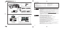
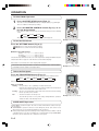
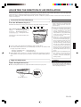
OPERATING MANUAL
MODE D’EMPLOI
MANUAL DE FUNCIONAMIENTO
HEAT&COOLING MODEL
(REVERSE CYCLE)
ROOM AIR CONDITIONER
WALL MOUNTED TYPE
Indoor Unit
English
ASU15RLQ
ASU18RLQ
Outdoor Unit
Español
Français
AOU15RLQ
AOU18RLQ
KEEP THIS OPERATION MANUAL
FOR FUTURE REFERENCE
FUJITSU GENERAL LIMITED
P/N9314969027-01
CONTENTS
Fig. 1
1
D
SAFETY PRECAUTIONS .................................... En-1
FEATURES AND FUNCTIONS ........................... En-2
NAME OF PARTS ................................................ En-3
PREPARATION .................................................... En-4
OPERATION ........................................................ En-5
AIR CLEANING OPERATION .............................. En-7
TIMER OPERATION ............................................ En-8
SLEEP TIMER OPERATION ............................... En-9
ADJUSTING THE DIRECTION OF
AIR CIRCULATION ........................................... En-10
2
Fig. 2
3
C
=
OPERATION
AB
5
@
#
TIMER
6
4
AIR CLEAN
COIL DRY
7
8
SAFETY PRECAUTIONS
DANGER!
Fig. 3
9
Fig. 5
I
G
H
J
SWING OPERATION ......................................... En-11
COIL DRY OPERATION ..................................... En-11
MANUAL AUTO OPERATION .......................... En-11
CLEANING AND CARE ..................................... En-12
CLEANING THE PLASMA
AIR CLEANING FILTER ..................................... En-13
TROUBLESHOOTING ....................................... En-16
OPERATING TIPS .............................................. En-17
Fig. 4
● Do not attempt to install this air conditioner by yourself.
● This unit contains no user-serviceable parts. Always consult authorized service personnel for repairs.
● When moving, consult authorized service personnel for disconnection and installation of the unit.
● Do not become excessively chilled by staying for lengthy periods in the direct cooling
airflow.
● Do not insert fingers or objects into the outlet port or intake grilles.
● Do not start and stop air conditioner operation by disconnecting the power supply
cord and so on.
● Take care not to damage the power supply cord.
● In the event of a malfunction (burning smell, etc.), immediately stop operation, disconnect the power supply plug, and consult authorized service personnel.
● If the power supply cord of this appliance is damaged, it should only be replaced by
the authorized service personal, since special purpose tools and specified cord are
required.
Fig. 6
K
CAUTION!
–
≠
(
)
+
¡
¢
§
•
ª
_
£
™
∞
¶
º
Ÿ
⁄
¤
‹
fi
‡
›
fl
●
●
●
●
●
●
●
●
●
●
●
●
●
●
●
●
●
●
°
Fig. 7
To facilitate explanation, the accompanying illustration has been drawn to show all possible indicators;
in actual operation, however, the display will only
show those indicators appropriate to the current operation.
●
●
●
En-1
Provide occasional ventilation during use.
Do not direct air flow at fireplaces or heating apparatus.
Do not climb on, or place objects on, the air conditioner.
Do not hang objects from the indoor unit.
Do not set flower vases or water containers on top of air conditioners.
Do not expose the air conditioner directly to water.
Do not operate the air conditioner with wet hands.
Do not pull power supply cord.
Turn off power source when not using the unit for extended periods.
Check the condition of the installation stand for damage.
Do not place animals or plants in the direct path of the air flow.
Do not drink the water drained from the air conditioner.
Do not use in applications involving the storage of foods, plants or animals, precision
equipment, or art works.
Connection valves become hot during Heating; handle with care.
Do not apply any heavy pressure to radiator fins.
Operate only with air filters installed.
Do not block or cover the intake grille and outlet port.
Ensure that any electronic equipment is at least one metre away from either the indoor or outdoor units.
Avoid installing the air conditioner near a fireplace or other heating apparatus.
When installing the indoor and outdoor unit, take precautions to prevent access to
infants.
Do not use inflammable gases near the air conditioner.
TYPE
TYPE
TIPO
HEAT & COOL MODEL
MODÈLE RÉVERSIBLE
MODELO DE REFRIGERACIÓN Y CAlEFACCÓN
MODEL
MODÈLE
MODELO
INDOOR UNIT
UNIDAD INTERIOR
UNITÉ INTÉRIEURE
ASU15RLQ
OUTDOOR UNIT
UNIDAD EXTERIOR
UNITÉ EXTÉRIEURE
AOU15RLQ
SPECIFICATIONS
POWER SUPPLY .......................................................................................................................................................................................................................................................... 208/230 V 60 Hz
COOLING
CAPACITY ................................................................................................................................................................................................................................................................... 15000 BTU/h
INPUT POWER .................................................................................................................................................................................................................................................................... 1.20 kW
CURRENT ................................................................................................................................................................................................................................................................................ 5.3 A
HEATING
CAPACITY ................................................................................................................................................................................................................................................................... 18000 BTU/h
INPUT POWER .................................................................................................................................................................................................................................................................... 1.43 kW
CURRENT ............................................................................................................................................................................................................................................................................... 6.3 A
FICHE TECHNIQUE
ALIMENTATION ........................................................................................................................................................................................................................................................... 208/230 V 60 Hz
REFROIDISSEMENT
PUISSANCE FRIGORIFIQUE ..................................................................................................................................................................................................................................... 15000 BTU/h
PUISSANCE ABSORBÉE .................................................................................................................................................................................................................................................... 1,20 kW
INTENSITÉ .............................................................................................................................................................................................................................................................................. 5,3 A
CHAUFFAGE
PUISSANCE FRIGORIFIQUE ..................................................................................................................................................................................................................................... 18000 BTU/h
PUISSANCE ABSORBÉE ................................................................................................................................................................................................................................................... 1,43 kW
INTENSITE .............................................................................................................................................................................................................................................................................. 6,3 A
ESPECIFICACIONES
ALIMENTACIÓN .......................................................................................................................................................................................................................................................... 208/230 V 60 Hz
REFRIGERACIÓN
CAPACIDAD ............................................................................................................................................................................................................................................................... 15000 BTU/h
ENTRADA DE ALIMENTACIÓN ......................................................................................................................................................................................................................................... 1,20 kW
CORRIENTE ............................................................................................................................................................................................................................................................................. 5,3 A
CALEFACCIÓN
CAPACIDAD ............................................................................................................................................................................................................................................................... 18000 BTU/h
ENTRADA DE ALIMENTACIÓN ......................................................................................................................................................................................................................................... 1,43 kW
CORRIENTE ............................................................................................................................................................................................................................................................................ 6,3 A
TYPE
TYPE
TIPO
HEAT & COOL MODEL
MODÈLE RÉVERSIBLE
MODELO DE REFRIGERACIÓN Y CAlEFACCÓN
MODEL
MODÈLL
MODELO
INDOOR UNIT
UNIDAD INTERIOR
UNITÉ INTÉRIEURE
ASU18RLQ
OUTDOOR UNIT
UNIDAD EXTERIOR
UNITÉ EXTÉRIEURE
AOU18RLQ
SPECIFICATIONS
POWER SUPPLY .......................................................................................................................................................................................................................................................... 208/230 V 60 Hz
COOLING
CAPACITY ................................................................................................................................................................................................................................................................... 18000 BTU/h
INPUT POWER .................................................................................................................................................................................................................................................................... 1.73 kW
CURRENT ................................................................................................................................................................................................................................................................................ 7.7 A
HEATING
CAPACITY ................................................................................................................................................................................................................................................................... 21600 BTU/h
INPUT POWER .................................................................................................................................................................................................................................................................... 1.93 kW
CURRENT ............................................................................................................................................................................................................................................................................... 8.6 A
FICHE TECHNIQUE
ALIMENTATION ........................................................................................................................................................................................................................................................... 208/230 V 60 Hz
REFROIDISSEMENT
PUISSANCE FRIGORIFIQUE ..................................................................................................................................................................................................................................... 18000 BTU/h
PUISSANCE ABSORBÉE ................................................................................................................................................................................................................................................... 1,73 kW
INTENSITÉ .............................................................................................................................................................................................................................................................................. 7,7 A
CHAUFFAGE
PUISSANCE FRIGORIFIQUE ..................................................................................................................................................................................................................................... 21600 BTU/h
PUISSANCE ABSORBEE .................................................................................................................................................................................................................................................... 1,93 kW
INTENSITE .............................................................................................................................................................................................................................................................................. 8,6 A
ESPECIFICACIONES
ALIMENTACIÓN .......................................................................................................................................................................................................................................................... 208/230 V 60 Hz
REFRIGERACIÓN
CAPACIDAD ............................................................................................................................................................................................................................................................... 18000 BTU/h
ENTRADA DE ALIMENTACIÓN ......................................................................................................................................................................................................................................... 1,73 kW
CORRIENTE ............................................................................................................................................................................................................................................................................. 7,7 A
CALEFACCIÓN
CAPACIDAD ............................................................................................................................................................................................................................................................... 21600 BTU/h
ENTRADA DE ALIMENTACIÓN ......................................................................................................................................................................................................................................... 1,93 kW
CORRIENTE ............................................................................................................................................................................................................................................................................. 8,6 A
FEATURES AND FUNCTIONS
INVERTER
At the start of operation, a large power is used to bring the
room quickly to the desired temperature. Afterwards, the
unit automatically switches to a low power setting for economic and comfortable operation.
COIL DRY OPERATION
The Indoor unit can be dried by pressing the COIL DRY button on the Remote Control Unit so as to avoid going moldy
and restrain the breed of bacterium.
SWING OPERATION
The Air Flow Direction Louvers swings automatically up and
down so that the air speeds to every nook and corner of
your room.
REMOVABLE OPEN PANEL
The indoor unit’s Open Panel can be removed for easy cleaning and maintenance.
MILDEW-RESISTANT FILTER
AUTO CHANGEOVER
The operation mode (cooling, dry, heating) is switched automatically to maintain the set temperature, and the temperature is kept constant at all times.
PROGRAM TIMER
The program timer allows you to integrate OFF timer and
ON timer operations in a single sequence. The sequence
can involve one transition from OFF timer to ON timer, or
from ON timer to OFF timer, within a twenty-four hour period.
The AIR FILTER has been treated to resist mildew growth,
thus allowing cleaner use and easier care.
SUPER QUIET OPERATION
When the FAN CONTROL button is used to select QUIET, the
unit begins super-quiet operation; the indoor unit’s airflow
is reduced to produce quieter operation.
AIR CLEANING MODE
Relies on the air conditioner’s power to quickly purify the air
in the room.
SLEEP TIMER
When the SLEEP button is pressed during Heating mode,
the air conditioner’s thermostat setting is gradually lowered
during the period of operation; during cooling mode, the
thermostat setting is gradually raised during the period of
operation. When the set time is reached, the unit automatically turns off.
ELECTRONIC AIR CLEAN FILTER
Install for use inside of the dust collection unit. For details
on how to install the filter, please refer to page 15.
Electrical power is used to charge the filter to remove contaminants from the air and to effectively collect dust and
remove odors. It also helps to reduce the bacterial activity.
WIRELESS REMOTE CONTROL UNIT
The Wireless Remote Control Unit allows convenient control of air conditioner operation.
WIRED REMOTE CONTROL UNIT (OPTION)
The optional wired remote control unit (model No.: UTB-UUB) can be used.
When you use remote control unit, there are following different points as compared with using wireless remote control unit.
[The additional functions for wired ones]
• Weekly timer
• Temperature set back timer
[The restricted functions for wired ones]
• Air-cleaning function can't be turned ON/OFF. (During operation, it is always ON)
• QUIET can't be selected in FAN MODE.
• Sleep-timer can't be used.
And you can't use both wired remote control unit and wireless simultaneously.
(Only one kind can be selected)
En-2
NAME OF PARTS
Fig. 1 Indoor Unit
Fig. 6 Remote Control Unit
1 Operating Control Panel (Fig. 2)
2 MANUAL AUTO button
● When kept on pressing the MANUAL
K
L
M
N
O
P
Q
R
S
T
U
V
W
Signal Transmitter
MASTER CONTROL button
FAN CONTROL button
START/STOP button
AIR CLEAN button
COIL DRY button
SET button
/
)
SET TEMP. button (
SLEEP button
SWING button
TIMER MODE button
TIMER SET (
/
)buttons
TEST RUN button
X
Y
Z
[
\
]
`
a
b
c
d
e
f
CLOCK ADJUST button
RESET button
Remote Control Unit Display (Fig. 7)
Temperature SET Display
Transmit Display
Operating Mode Display
Fan Speed Display
AIR CLEAN Display
SWING Display
COIL DRY Display
Timer Mode Display
SLEEP Display
Clock Display
AUTO button for more than 10 seconds,
the forced cooling operation will start.
● The forced cooling operation is used at the
time of installation.
Only for authorized service personnel’s
use.
● When the forced cooling operation starts
by any chance, press the START/STOP
button to stop the operation.
3
4
5
6
Indicator (Fig. 3)
Remote Control Signal Receiver
OPERATION Indicator Lamp (red)
TIMER Indicator Lamp (green)
● If the TIMER indicator lamp flashes when
the timer is operating, it indicates that a
fault has occurred with the timer setting
(See Page 17 Auto Restart).
7 AIR CLEAN Indicator Lamp (green)
8 COIL DRY Indicator Lamp (orange)
9
0
A
B
C
D
E
F
Intake Grille (Fig. 4)
Air Filter
Air Flow Direction Louver
Right-Left Louver
(behind Air Flow Direction Louver)
Drain Hose
Electrical Air Cleaning Filter
Power Supply Cord
Power Supply Plug
Fig. 5 Outdoor Unit
G
H
I
J
Intake Port
Outlet Port
Pipe Unit
Drain port (bottom)
● Refer to the folded out page on the cover.
En-3
● This button is used when installing the
conditioner, and should not be used under normal conditions, as it will cause the
air conditioner’s thermostat function to operate incorrectly.
● If this button is pressed during normal operation, the unit will switch to test operation mode, and the Indoor Unit’s OPERATION Indicator Lamp and TIMER Indicator
Lamp will begin to flash simultaneously.
● To stop the test operation mode, press the
START/STOP button to stop the air conditioner.
PREPARATION
CAUTION!
Turn on the Power
1
Connect the Power Supply Plug (Fig. 1 F) to an electrical outlet; in the case of a direct line connection, turn
on the circuit breaker.
Load Batteries (AAA/R03/LR03 × 2)
1
Press and slide the battery compartment lid on the reverse side to open it.
Slide in the direction of the arrow while pressing the
2
Insert batteries.
3
Close the battery compartment lid.
Be sure to align the battery polarities (
mark.
) correctly.
● Take care to prevent infants from
accidentally swallowing batteries.
● When not using the Remote Control Unit
for an extended period, remove the
batteries to avoid possible leakage and
damage to the unit.
● If leaking battery fluid comes in contact
with your skin, eyes, or mouth, immediately wash with copious amounts of
water, and consult your physician.
● Dead batteries should be removed
immediately and disposed of properly,
either in a battery collection receptacle
or to the appropriate authority.
● Do not attempt to recharge dry batteries.
Never mix new and used batteries, or
batteries of different types.
Batteries should last about one year
under normal use. If the Remote Control Unit’s operating range becomes appreciably reduced, replace the batteries
and press the RESET button with the tip
of a ballpoint pen or other small object.
Set the Current time
1
2
Press the CLOCK ADJUST button (Fig. 6 X).
Use the tip of a ball-point pen or other small object to press the button.
Use the TIMER SET ( / ) buttons (Fig. 6 V) to adjust the clock to the current time.
button: Press to advance the time.
button: Press to reverse the time.
(Each time the buttons are pressed, the time will be advanced/reversed in
one-minute increments; hold the buttons depressed to change the time
quickly in ten-minute increments.)
3
Press the CLOCK ADJUST button (Fig. 6 X) again.
This completes the time setting and starts the clock.
To Use the Remote Control Unit
● The Remote Control Unit must be pointed at signal receiver (Fig. 3 4) to operate
correctly.
● Operating Range: About 23 ft.
● When a signal is properly received by the air conditioner, a beeping sound will
be heard.
● If no beep is heard, press the Remote Control Unit button again.
Remote Control Unit Holder
Insert
Slide up
Press in
Pull out
Screws
1 Mount the Holder.
2 Set the Remote Control
Unit.
3 To remove the Remote
Control Unit (when use at
hand).
En-4
OPERATION
To Select Mode Operation
1
Press the START/STOP button (Fig.6 N).
2
Press the MASTER CONTROL button (Fig.6 L) to select the desired mode.
The indoor unit’s OPERATION Indicator Lamp (red) (Fig. 3 5) will light.
The air conditioner will start operating.
Each time the button is pressed, the mode will change in the following
order.
s AUTO
s COOL
s DRY
HEAT t
FAN t
About three seconds later, the entire display will reappear.
Example: When set to COOL.
To Set the Thermostat
Press the SET TEMP. button (Fig. 6 R).
button: Press to raise the thermostat setting.
button: Press to lower the thermostat setting.
●Thermostat setting range:
AUTO .................................. 64 °F to 88 °F
Heating ............................... 60 °F to 88 °F
Cooling/Dry ........................ 64 °F to 88 °F
The thermostat cannot be used to set room temperature during the FAN mode (the
temperature will not appear on the Remote Control Unit’s Display).
About three seconds later, the entire display will reappear.
The thermostat setting should be considered a standard value, and may differ
somewhat from the actual room temperature.
Example: When set to 80 °F.
To Set the Fan Speed
Press the FAN CONTROL button (Fig. 6 M).
Each time the button is pressed, the fan speed changes in the following order:
sAUTO
s HIGH
s
MED
sLOW
s QUIET
About three seconds later, the entire display will reappear.
When set to AUTO:
Heating : Fan operates so as to optimally circulate warmed air.
However, the fan will operate at very low speed when the temperature
of the air issued from the indoor unit is low.
Cooling : As the room temperature approaches that of the thermostat setting,
the fan speed becomes slower.
Fan
: The fan runs at the low fan speed.
The fan will operate at a very low setting during Monitor operation
and at the start of the Heating mode.
SUPER QUIET Operation
SUPER QUIET operation begins. The indoor unit’s airflow will be reduced for quieter operation.
● SUPER QUIET operation cannot be used during Dry mode. (The same is true
when dry mode is selected during AUTO mode operation.)
● During Super Quiet operation, Heating and Cooling performance will be reduced
somewhat. If the room does not warm up/ cool down when using SUPER QUIET
Operation, please adjust the air conditioner’s Fan Speed.
En-5
Example: When set to AUTO.
To Stop Operation
Press the START/STOP button (Fig.6 N).
The OPERATION Indicator Lamp (red) (Fig. 3 5) will go out.
About AUTO CHANGEOVER Operation
AUTO:
● When AUTO CHANGEOVER operation first selected, the fan will operate at very low speed for about one minute, during which time the unit
detects the room conditions and selects the proper operating mode.
If the differance between thermostat setting and actual room temperature is more than +4 °F → Cooling or dry operation
If the difference between thermostat setting and actual room temperature is within ±4 °F → Monitor operation
If the difference between thermostat setting and actual room temperature is more than –4 °F → Heating operation
● When the air conditioner has adjusted your room’s temperature to near
the thermostat setting, it will begin monitor operation. In the monitor
operation mode, the fan will operate at low speed. If the room temperature subsequently changes, the air conditioner will once again
select the appropriate operation (Heating, Cooling) to adjust the temperature to the value set in the thermostat.
(The monitor operation range is ±4 °F relative to the thermostat setting.)
● If the mode automatically selected by the unit is not what you wish,
select one of the mode operation (HEAT, COOL, DRY, FAN).
About Mode Operation
Heating: ● Use to warm your room.
● When Heating mode is selected, the air conditioner will operate at very
low fan speed for about 3 to 5 minutes, after which it will switch to the
selected fan setting. This period of time is provided to allow the indoor
unit to warm up before begin full operation.
● When the room temperature is very low, frost may form on the outside
unit, and its performance may be reduced. In order to remove such
frost, the unit will automatically enter the defrost cycle from time to
time. During Automatic Defrosting operation, the OPERATION Indicator Lamp (red) (Fig. 3 5)will flash, and the heat operation will be interrupted.
Cooling: ● Use to cool your room.
Dry:
● Use for gently cooling while dehumidifying your room.
● You cannot heat the room during Dry mode.
● During Dry mode, the unit will operate at low speed; in order to adjust
room humidity, the indoor unit’s fan may stop from time to time. Also,
the fan may operate at very low speed when adjusting room humidity.
During Heating mode:
Set the thermostat to a temperature setting that is higher than the current room
temperature. The Heating mode will not
operate if the thermostat is set lower than
the actual room temperature.
During Cooling/Dry mode:
Set the thermostat to a temperature setting that is lower than the current room
temperature. The Cooling and Dry modes
will not operate if the thermostat is set
higher than the actual room temperature
(in Cooling mode, the fan alone will operate).
During Fan mode:
You can not use the unit to heat and cool
your room.
● The fan speed cannot be changed manually when Dry mode has been
selected.
Fan:
● Use to circulate the air throughout your room.
En-6
AIR CLEANING OPERATION
If you wish to eliminate dirt,dust,cigarette smoke, pollen, or just simply purify the
air of the room, use the Air Cleaning Mode.
1
Press the START/STOP button (Fig. 6 N).
2
Press the AIR CLEAN button (Fig. 6 O).
The OPERATION Indicator Lamp (red) (Fig. 3 5) will light.
(If the unit is already in operation, please proceed to step 2.)
The AIR CLEAN Indicator Lamp (green) (Fig. 3 7) will light up.
● Air conditioning and Air Cleaning will function simultaneously.
If you wish to stop Air Clean
Press the AIR CLEAN button (Fig. 6 O) once again.
The AIR CLEAN Indicator Lamp (green) (Fig. 3 7) will go out.
● This will only stop the Air Cleaning, the air conditioner will continue operating.
To also stop the air conditioner
Press the START/STOP button (Fig. 6 N).
The OPERATION Indicator Lamp (red) (Fig. 3 5) will go out.
● The next time the START / STOP button (Fig. 6 N) is pressed air conditioning
and air cleaning will both resume operating.
Air cleaning
● During operation, the unit produces a small amount of ozone that can be smelled.
● When this unit is used in combination with the ultrasonic humidifier, white parti-
cles may become attached to the plasma filter unit. If this happens, clean the
plasma filter unit as soon as possible. (Refer to page 13, 14.)
● The air cleaning operation cannot remove gases such as carbon monoxide and
alcohol from the air. During operation, ventilate the room often to prevent asphyxiation or suffocation.
● If the intake filter is removed during operation, a safety device will stop the op-
eration of the plasma filter unit. If this happens, the AIR CLEAN Indicator Lamp
(green) on the indoor unit will flash after some time has passed. Use the START/
STOP button on the remote controller to stop the operation, install the intake
filter, and then use the START/STOP button to restart the operation.
● Use the FAN CONTROL button to change the fan speed. (Refer to page 5.) The
plasma filter unit operates most effectively at the highest fan speed.
● The AIR CLEAN Indicator Lamp (green) will flash to inform you that the periodic
cleaning of the plasma filter unit is required. (Refer to page 13, 14.)
En-7
TIMER OPERATION
Before using the timer function, be sure that the Remote Control Unit is set to the correct current time (☞ P. 4).
To Use the ON timer or OFF timer
1
Press the START/STOP button (Fig. 6 N)
(if the unit is already operating, proceed to step 2).
The indoor unit’s OPERATION Indicator Lamp (red) (Fig. 3 5) will light.
2
Press the TIMER MODE button (Fig. 6 U) to select the
OFF timer or ON timer operation.
Each time the button is pressed the timer function changes in the following order:
s CANCEL
s OFF
sON
PROGRAM(OFF → ON, OFF ← ON) t
The indoor unit’s green TIMER Indicator Lamp (Fig. 3 6) will light.
3
Use the TIMER SET buttons (Fig. 6 V) to adjust the
desired OFF time or ON time.
Set the time while the time display is flashing (the flashing will continue
for about five seconds).
To Cancel the Timer
Use the TIMER MODE button to select
“CANCEL”.
The air conditioner will return to normal
operation.
To Change the Timer Settings
Perform steps 2 and 3.
To Stop Air Conditioner Operation
while the Timer is Operating
Press the START/STOP button.
To Change Operating Conditions
If you wish to change operating conditions
(Mode, Fan Speed, Thermostat Setting,
SUPER QUIET mode) after making the
timer setting, wait until the entire display
reappears, then press the appropriate
buttons to change the operating condition
desired.
button: Press to advance the time.
button: Press to reverse the time.
About five seconds later, the entire display will reappear.
To Use the Program timer
1
Press the START/STOP button (Fig. 6 N).
(if the unit is already operating, proceed to step 2).
The indoor unit’s OPERATION Indicator Lamp (red) (Fig. 3 5) will light.
2
3
Set the desired times for OFF timer and ON timer.
See the section “To Use the ON timer or OFF timer” to set the desired
mode and times.
About three seconds later, the entire display will reappear.
The indoor unit’s TIMER Indicator Lamp (green) (Fig. 3 6) will light.
Press the TIMER MODE button (Fig. 6 U) to select the
ON or OFF
ON
PROGRAM timer operation (OFF
will display).
The display will alternately show “OFF timer” and “ON timer”, then change
to show the time setting for the operation to occur first.
● The program timer will begin operation. (If the ON timer has been selected to operate first, the unit will stop operating at this point.)
About five seconds later, the entire display will reappear.
About the Program timer
To Cancel the Timer
Use the TIMER MODE button to select
“CANCEL.”
The air conditioner will return to normal
operation.
To Change the Timer Settings
1. Follow the instructions given in the section
“To Use the ON Timer or OFF Timer” to select the timer setting you wish to change.
2. Press the TIMER MODE button to select
either OFF
ON or OFF
ON.
To Stop Air Conditioner Operation
while the Timer is Operating
Press the START/STOP button.
To Change Operating Conditions
If you wish to change operating conditions
(Mode, Fan Speed, Thermostat Setting,
SUPER QUIET mode), after making the timer
setting wait until the entire display reappears, then press the appropriate buttons to
change the operating condition desired.
● The program timer allows you to integrate OFF timer and ON timer operations in
a single sequence. The sequence can involve one transition from OFF timer to
ON timer, or from ON timer to OFF timer, within a twenty-four hour period.
● The first timer function to operate will be the one set nearest to the current time.
The order of operation is indicated by the arrow in the Remote Control Unit’s
Display (OFF → ON, or OFF ← ON).
● One example of Program timer use might be to have the air conditioner auto-
matically stop (OFF timer) after you go to sleep, then start (ON timer) automatically in the morning before you arise.
En-8
SLEEP TIMER OPERATION
Unlike other timer functions, the SLEEP timer is used to set the length of time until air conditioner operate is stopped.
To Use the SLEEP Timer
While the air conditioner is operating or stopped, press the
SLEEP button (Fig. 6 S).
The indoor unit’s OPERATION Indicator Lamp (red) (Fig. 3 5) lights and the TIMER
Indicator Lamp (green) (Fig. 3 6) light.
To Cancel the Timer:
Use the TIMER MODE button to select
“CANCEL”.
The air conditioner will return to normal
operation.
To Stop the Air Conditioner During
Timer Operation:
To Change the Timer Settings
Press the START/STOP button.
Press the SLEEP button (Fig. 6 S) once again and set the time
) buttons (Fig. 6 V).
using the TIMER SET( /
Set the time while the Timer Mode Display is flashing (the flashing will continue
about five seconds).
button: Press to advance the time.
button: Press to reverse the time.
About five seconds later, the entire display will reappear.
About the SLEEP Timer
To prevent excessive warming or cooling during sleep, the SLEEP timer function automatically modifies the thermostat setting
in accordance with the set time setting. When the set time has elapsed, the air conditioner completely stops.
During Heating operation:
When the SLEEP timer is set, the thermostat setting is
automatically lowered 2 °F every thirty minutes. When the thermostat has been lowered a total of 8 °F, the thermostat setting
at that time is maintained until the set time has elapsed, at
which time the air conditioner automatically turns off.
SLEEP timer setting
During Cooling/Dry operation:
When the SLEEP timer is set, the thermostat setting is automatically raised 2 °F every sixty minutes. When the thermostat has been raised a total of 8 °F, the thermostat setting at
that time is maintained until the set time has elapsed, at which
time the air conditioner automatically turns off.
SLEEP timer setting
2 °F
4 °F
6 °F
30
minutes
8 °F
Set time
1 hour
1 hour
1 hour
30 minutes
Set time
En-9
2 °F
4 °F
ADJUSTING THE DIRECTION OF AIR CIRCULATION
Vertical (up-down) direction of airflow is adjusted by pressing the Remote Control Unit’s SET button. Horizontal (right-left)
airflow direction is adjusted manually, by moving the Air Flow Direction Louvers.
Whenever making horizontal airflow adjustments, start air conditioner operation and be sure that the vertical air direction
louvers are stopped.
R DANGER!
Vertical Air Direction Adjustment
Press the SET button (Fig. 6 Q).
Each time the button is pressed, the air direction range will change as follows:
1
2
3
4
5
6
7
● Always use the Remote Control Unit’s
SET button to adjust the vertical airflow
louvers. Attempting to move them
manually could result in improper operation; in this case, stop operation and
restart. The louvers should begin to
operate properly again.
Types of Air flow Direction Setting:
1,2,3
: During Cooling/Dry modes
4,5,6,7 : During Heating mode
1,2,3,4,5,6,7 : During Fan mode
The Remote Control Unit’s display does
not change.
● Use the air direction adjustments within the ranges shown above.
● The vertical airflow direction is set automatically as shown, in accordance with
the type of operation selected.
During Cooling/Dry mode : Horizontal flow 1
During Heating mode
● Never place fingers or foreign objects inside the outlet ports, since the internal fan
operates at high speed and could cause
personal injury.
: Downward flow 7
● During AUTO mode operation, for the first minute after beginning operation,
airflow will be horizontal 1; the air direction cannot be adjusted during this period.
Right-Left Adjustment
● During use of the Cooling and Dry
modes, do not set the Air Flow Direction Louvers in the Heating range (4 7) for long periods of time, since water vapor may condense near the outlet louvers and drops of water may drip
from the air conditioner. During the
Cooling and Dry modes, if the Air Flow
Direction Louvers are left in the heating range for more than 30 minutes,
they will automatically return to position 3.
● When used in a room with infants, children, elderly or sick persons, the air
direction and room temperature
should be considered carefully when
making settings.
R DANGER!
Adjust the Right-Left louvers.
● Move the Right-Left louvers to adjust air flow in the direction you prefer.
● When adjusting the Right-Left Louvers, it
is necessary to stop the Air-Conditioner
first and make sure that it stops completely
before adjusting the direction.
knob
knob(three places)
En-10
SWING OPERATION
Begin air conditioner operation before performing this procedure.
To select SWING Operation
Press the SWING button (Fig. 6 T).
The SWING Display (Fig. 7 b) will light.
In this mode, the Air Flow Direction Louvers will swing automatically to direct the
air flow both up and down.
To stop SWING Operation
Press the SWING button (Fig. 6 T) once again.
The SWING Display (Fig. 7 b) will go out.
Airflow direction will return to the setting before swing was begun.
About Swing Operation
During cooling/Dry mode : Swings between 1 and 3.
During heating mode
: Swings between 3 and 7.
● The SWING operation may stop temporarily when the air conditioner’s fan is not
operating, or when operating at very low speeds.
COIL DRY OPERATION
The Indoor unit can be dried by pressing the COIL DRY button on the Remote Control Unit so as to avoid going moldy and
restrain the breed of bacterium.
The COIL DRY Operation will operate for 30 minutes after pressing the COIL DRY button and it will stop automatically.
To select COIL DRY Operation
Press the COIL DRY button (Fig. 6 P) during operation or when
it stops.
The COIL DRY Indicator Lamp (orange) (Fig. 3 8) and the COIL DRY Display (Fig. 7
c) will light. Then it will disappear after 30 minutes.
To cancel COIL DRY Operation
Press the START/STOP button (Fig. 6 N) during COIL DRY
Operation.
The COIL DRY Indicator Lamp (orange) (Fig. 3 8) and the COIL DRY Display (Fig. 7
c) will go out . Then the operation stops.
About COIL DRY Operation
● Press the COIL DRY button again during COIL DRY Operation, COIL DRY Operation can be reset.
● The COIL DRY Operation cannot get rid of the existed mould or bacterium, and it
has no sterilization effect either.
MANUAL AUTO OPERATION
Use the MANUAL AUTO operation in the event the Remote Control Unit is lost or otherwise unavailable.
How To Use the Main Unit Controls
Press the MANUAL AUTO button (Fig. 2 2) on the main unit
control panel.
To stop operation, press the MANUAL AUTO button (Fig. 2 2) once again.
(Controls are located inside the Open Panel)
En-11
● When the air conditioner is operated
with the controls on the Main Unit, it
will operate under the same mode as
the AUTO mode selected on the Remote Control Unit (see page 6).
● The fan speed selected will be “AUTO”
and the thermostat setting will be
standard.(76 °F)
CLEANING AND CARE
CAUTION!
● Before cleaning the air conditioner, be sure to turn it off and disconnect the Power Supply Cord.
● Be sure the Intake Grille (Fig. 4 9) is installed securely.
● When removing and replacing the air filters, be sure not to touch the heat exchanger, as personal injury may result.
Cleaning the Intake Grille
Cleaning the Air Filter
1. Remove the Intake Grille.
1 Place your fingers at both lower ends of the grille
panel, and lift forward; if the grille seems to catch
partway through its movement, continue lifting upward to remove.
1. Open the Intake Grille, and remove the air
filter.
Lift up the air filter’s handle, disconnect the two lower
tabs, and pull out.
2 Pull past the intermediate catch and open the Intake
Grille wide so that it become horizontal.
Air filter handle
Intake Grille
2. Remove dust with a vacuum cleaner or by
washing.
Intake Grille
After washing, allow to dry thoroughly in a shaded place.
Mounting
shaft
3. Replace the Air Filter and close the Intake
Grille.
1 Align the sides of the air filter with the panel, and push
in fully, making sure the two lower tabs are returned
properly to their holes in the panel.
Knob
2. Clean with water.
Remove dust with a vacuum cleaner; wipe the unit with
warm water, then dry with a clean, soft cloth.
3. Replace the Intake Grille.
1 Pull the knobs all the way.
2 Hold the grille horizontal and set the left and right
mounting shafts into the bearings at the top of the
panel.
3 Press the place where the arrow on the diagram indicates and close the Intake Grille.
Bearing
● Dust can be cleaned from the air filter either with a vacuum
cleaner, or by washing the filter in a solution of mild detergent and warm water. If you wash the filter, be sure to
allow it to dry thoroughly in a shady place before reinstalling.
Knob
● If dirt is allowed to accumulate on the air filter, air flow
will be reduced, lowering operating efficiency and increasing noise.
Mounting shaft
Intake
Grille
2 Close the Intake Grille.
(For purposes of example, the illustration shows the unit
without Intake Grille installed.)
● During periods of normal use, the Air Filters should be
cleaned every two weeks.
Intake Grille
Mounting
shaft
Knob
● When used for extended periods, the unit may accumulate dirt inside, reducing its performance. We recommend that the
unit be inspected regularly, in addition to your own cleaning and care. For more information, consult authorized service
personnel.
● When cleaning the unit’s body, do not use water hotter than 104 °F, harsh abrasive cleansers, or volatile agents like
benzene or thinner.
● Do not expose the unit body to liquid insecticides or hairsprays.
● When shutting down the unit for one month or more, first allow the fan mode to operate continuously for about one-half
day to allow internal parts to dry thoroughly.
En-12
CLEANING THE PLASMA AIR CLEANING FILTER
WARNING!
Before cleaning the plasma filter unit, be sure to turn off the power supply to the air conditioner.
Electric shock may result.
CAUTION!
● Make sure the plasma filter unit is properly mounted before cleaning or performing other tasks
on it. If the unit is not properly mounted, it could fall off and cause damage or injury.
● You can be injured if you touch the heat exchanger when removing or installing the plasma filter
unit. Do not insert your fingers between the plasma filter unit and the heat exchanger.
Regarding the Air Cleaning check function
● This function is illustrated by the flashing of the AIR CLEAN Indicator Lamp (green), indicating that the unit requires
maintenance.
After Air Cleaning Mode has been in use for approximately 400 hours, the AIR CLEAN Indicator Lamp (green) will begin to
slowly flash (approximately once every 7 seconds). When this occurs, the unit requires maintenance.
After Air Cleaning Mode has been in use for approximately 500 hours, the AIR CLEAN Indicator Lamp (green) will begin to
flash quickly (approximately once every 3 seconds). At this point, Air Cleaning will cease functioning. Please carry out
appropriate maintenance for the unit.
● Please carry out unit maintenance every 6 months.
● If a squeaking or chirping sound is heard, unit maintenance needs to be carried out, even if the AIR CLEAN Indicator Lamp
(green) is not flashing.
Cleaning the dust collection unit
1. Open the intake grille and remove the air
filter on the right.
● Please consult the instructions for cleaning the air
filter on page 12.
2. Remove the dust collection unit.
4. Wash with water and dry.
1 Soak the plasma filter unit in warm water (104 to
113˚F) for 10 to 15 minutes. If the plasma filter unit is
extremely dirty, extremely dilute a mild synthetic laundry detergent (low alkalinity or isotope detergent) to
15 times the standard concentration and allow the
plasma filter unit to soak in it.
2 Gently move up and down and to the right and left. A
soft sponge can also be used to wipe the surface.
3 Rinse with clean water.
4 Shake the plasma filter unit to drain off the water. (If
the plasma filter unit is extremely dirty, repeat Steps
1 through 4 two or three more times.)
5 Place the plasma filter unit in the shade and allow it
to dry completely.
handle
Securely grasp the dust collection unit by the handle and
pull it out (as shown by the arrow).
(The above figure is only for reference, so the intake grille
is not included).
3. Remove the air cleaning & deodorizing filter from the cleaning unit.
1 Open the filter case at the rear of cleaning unit.
Claw
● Never disassemble the plasma filter unit.
Claw
Filter case
● Never soak the plasma filter unit in hot water.
● Never wipe the plasma filter unit with a scrub brush
or other hard or abrasive items. This will damage
the honey comb filter.
2 Remove the air cleaning & deodorizing filter.
Air cleaning &
deodorizing filter
En-13
● Only use a mild synthetic laundry detergent (low
alkalinity or isotope detergent).
● Never insert a brush into the inside of plasma filter
unit for washing. This will damage the internal parts
and cause malfunctioning of the plasma filter unit.
● Never use dryer or other device to blow hot air on
the plasma filter unit. This will cause deformation
or other damage.
● Before re-installing the unit, please wait until it is
completely dry. If the unit is installed when still wet
and then put into operation, the OPERATION Indicator Lamp (red) and the TIMER Indicator Lamp
(green) will flash and Air Cleaning will stop.
Cleaning the dust collection unit
5. Install the unit.
6. Install the air filter.
(The above figure is only for reference, so the intake grille
is not included.)
● Please consult instructions for cleaning the air filter
on page 12.
7. Close the intake grille.
Push the intake grill in at 4 points (the two ends of its
lower side as well as two center points of the lower side,
as shown in the figure) to close it.
1 Align the two ends of the dust collection
unit with the guide rail and slide in.
Guide rail
Please ensure that the intake grille is
closed properly.
● If, after cleaning the dust collection unit, the
operation indicator lamp and the timer indicator
lamp flash during Air Cleaning, please ensure that
the unit is not damp and that the intake grille is
properly closed.
● If, after having checked that the unit is fully dry and
that the intake grille is closed properly, the indicator
lamps continue to flash, the dust collection unit may
be damaged. Please consult an authorised dealer
to obtain a replacement.
2 Slide in until it clicks.
“Click”
“Click”
WARNING!
●Be sure the Intake Grille (Fig. 4 9) is installed
securely.
● Please ensure that the dust collection unit is
completely dry before installing.
● After installing the dust collection unit, please
ensure that it has been inserted fully into its place.
If it has not been installed correctly, the OPERATION
Indicator Lamp (red) and the TIMER Indicator Lamp
(green) will flash, and Air Cleaning will stop.
En-14
How to install or remove the Aircleaning and Deodorizing filter
1. Remove the dust-collecting unit.
● Please consult steps 1 and 2 of cleaning the dustcollecting unit on page 13.
2. Install or remove the Air-cleaning and
Deodorizing filter into the unit.
1 Open the filter case inside the dust-collecting unit.
Hook
Air-cleaning and Deodorizing filter
maintenance
As well as ensuring the maintenance of the dust collecting
unit, please also take care of the filter.
(Please carry out maintenance on the filter every 6 months.)
1. Open the intake grille and remove the air
filter from the right side.
● Please consult step 1 of cleaning the air filter on page 12.
2. Take out the unit and remove the Aircleaning and Deodorizing filter.
Hook
Filter case
● Please consult steps 2 and 3 of cleaning the air filter
on page 13.
3. Air-dry after washing.
1 Wash using lukewarm or warm water. If quite dirty,
wash using a mild detergent.
2 Insert or remove the Air-cleaning and Deodorizing filter
into the dust-collecting unit.
Please do not rub the filter, it may cause its Aircleaning performance to be reduced.
2 Rinse it under running water.
Install
3 Allow it to dry thoroughly in a shaded place.
4. Install the Air-cleaning and Deodorizing
filter.
● Please consult the instructions on how to install the
filter on page 15.
Filter
Remove
● Please place the air cleaning & deodorizing
filter, with the black surface upward.
3 Close the filter case.
Filter Case
“Click”
Hook
Hook
“Click”
● Please ensure that the filter case is properly
closed. If the filter case is not properly closed,
the filter could fall out.
3. Install the dust-collection unit.
● Please consult steps 5, 6 and 7 of cleaning the dustcollection unit on page 14.
❇ When removing the filter, please follow these
steps backwards.
En-15
5. Install the air filter and close the intake
grille.
● Please consult step 3 of cleaning the air filter on
page 12.
Regarding the Air-cleaning and Deodorizing filter
● Please change the filter approximately every 2 years to
ensure good Air-cleaning performance. (This is only
possible if the filter is cleaned once every six months)
When changing the filter, please make sure you purchase
the correct model (UTR – FA14).
● Please only install filters that are licensed by our
company.
● Regarding storage and care of the filter, please avoid
exposing it to high temperatures and high humidity.
Also, use it as soon as possible after opening its
packaging.
TROUBLESHOOTING
WARNING!
In the event of a malfunction (burning smell, etc.), immediately stop operation, disconnect the
Power Supply Plug, and consult authorized service personnel.
Merely turning off the unit’s power switch will not completely disconnect the unit from the power
source. Always be sure to disconnect the Power Supply Plug or turn off your circuit breaker to
ensure that power is completely off.
Before requesting service, perform the following checks:
NORMAL
FUNCTION
Symptom
Problem
Doesn’t operate immediately:
● If the unit is stopped and then immediately started again, the compressor will not operate for about 3 minutes, in order to prevent
fuse blowouts.
● Whenever the Power Supply Plug is disconnected and then reconnected to a power outlet, the protection circuit will operate for
about 3 minutes, preventing unit operation during that period.
Noise is heard:
● During operation and immediately after stopping the unit, the
sound of water flowing in the air conditioner’s piping may be
heard. Also, noise may be particularly noticeable for about 2 to 3
minutes after starting operation (sound of coolant flowing).
See Page
—
—
● During operation, a slight squeaking sound may be heard. This is
the result of minute expansion and contraction of the front cover
due to temperature changes.
Smells:
Mist or steam are
emitted:
Airflow is weak or stops:
● During Heating operation, a sizzling sound may be heard occasional.
This sound is produced by the Automatic Defrosting operation.
17
● Some smell may be emitted from the indoor unit. This smell is
the result of room smells (furniture, tobacco, etc.) which have
been taken into the air conditioner.
—
● During Cooling or Dry operation, a thin mist may be seen emitted
from the indoor unit. This results from the sudden Cooling of
room air by the air emitted from the air conditioner, resulting in
condensation and misting.
—
● During Heating operation, the outdoor unit’s fan may stop, and
steam may be seen rising from the unit. This is due to Automatic
Defrosting operation.
17
● When Heating operation is started, fan speed is temporarily very
low, to allow internal parts to warm up.
● During Heating operation, if the room temperature rises above
the thermostat setting, the outdoor unit will stop, and the indoor
unit will operate at very low fan speed. If you wish to warm the
room further, set the thermostat for a higher setting.
—
● During Heating operation, the unit will temporarily stop operation (between 7 and 15 minutes) as the Automatic Defrosting mode
operates. During Automatic Defrosting operation, the OPERATION
Indicator Lamp will flash.
17
● The fan may operate at very low speed during Dry operation or
when the unit is monitoring the room’s temperature.
5
● During SUPER QUIET operation, the fan will operate at very low
speed.
5
● In the monitor AUTO operation, the fan will operate at very low
speed.
5
Water is produced from
the outdoor unit:
● During Heating operation, water may be produced from the outdoor unit due to Automatic Defrosting operation.
17
The AIR CLEAN Indicator
Lamp (green) will begin
to slowly flash (as shown
in the figure):
● After approximately 400 hours of Air Cleaning Mode use, the AIR
CLEAN Indicator Lamp will begin to flash slowly (as shown in the
figure). When this occurs, please stop the system, remove the
mains socket and carry out maintenance on the dust collecting
unit's air filter.
13-14
The AIR CLEAN Indicator
Lamp (green) will begin
to flash quickly (as shown
in the figure):
● After approximately 500 hours of Air Cleaning Mode use, the AIR
CLEAN Indicator Lamp will begin to flash quickly (as shown in
the figure). At this point, Air Cleaning will stop functioning. Please
stop the system, remove the mains socket and carry out maintenance on the dust collecting unit's air filter.
13-14
En-16
TROUBLESHOOTING
Items to check
Symptom
CHECK ONCE
MORE
Doesn’t operate at all:
See Page
● Is the Power Supply Plug disconnected its outlet?
● Has there been a power failure?
—
● Has a fuse blown out, or a circuit breaker been tripped?
● Is the timer operating?
Poor Cooling performance:
8-9
● Is the Air Filter dirty?
● Air the air conditioner’s intake grille or outlet port blocked?
● Did you adjust the room temperature settings (thermostat) correctly?
● Is there a window or door open?
—
● In the case of Cooling operation, is a window allowing bright sunlight to enter? (Close the curtains.)
● In the case of Cooling operation, are there heating apparatus and
computers inside the room, or are there too many people in the
room?
● Is the unit set for SUPER QUIET operation?
The unit operates
differently from the Remote
Control Unit’s setting:
5
● Are the Remote Control Unit’s batteries dead?
● Are the Remote Control Unit’s batteries loaded properly?
4
If the problem persists after performing these checks, or if you notice burning smells, or the OPERATION Indicator Lamp
(Fig. 3 5) and the TIMER Indicator Lamp (Fig. 3 6) flashes, immediately stop operation, disconnect the Power Supply Plug
(Fig. 1 F), and consult authorized service personnel.
OPERATING TIPS
Operation and Performance
Heating Performance
● This air conditioner operates on the heat-pump principle, absorbing heat from outdoor air and transferring that
heat indoors. As a result, the operating performance is
reduced as outdoor air temperature drops. If you feel that
insufficient heating performance is being produced, we
recommend you use this air conditioner in conjunction
with another kind of heating appliance.
● Heat-pump air conditioners heat your entire room by
recirculating air throughout the room, with the result that
some time may be required after first starting the air conditioner until the room is heated.
Microcomputer-controlled Automatic Defrosting
● When using the Heating mode under conditions of low
outdoor temperature and high humidity, frost may form
on the outdoor unit, resulting in reduced operating performance.
In order to prevent this kind of reduced performance, this
unit is equipped with a Microcomputer-controlled Automatic Defrosting function. If frost forms, the air conditioner will temporarily stop, and the defrosting circuit will
operate briefly (for about 7-15 minutes).
During Automatic Defrosting operation, the OPERATION
Indicator Lamp (red) will flash.
AUTO Restart
In Event of Power Interruption
● The air conditioner power has been interrupted by a
power failure. The air conditioner will then restart automatically in its previous mode when the power is restored.
● Operated by setting before the power failure.
En-17
● If a power failure occurs during TIMER operation, the timer
will be reset and the unit will begin (or stop) operation at the
new time setting. In the event that this kind of timer fault
occurs the TIMER Indicator Lamp will flash (see Page. 3).
● Use of other electrical appliances (electric shaver, etc.) or
nearby use of a wireless radio transmitter may cause the
air conditioner to malfunction. In this event, temporarily
disconnect the Power Supply Plug, reconnect it, and then
use the Remote Control Unit to resume operation.
OPERATING TIPS
Temperature and Humidity Range
Cooling Mode
Dry Mode
Heating Mode
Outdoor temperature
About 14 °F to 115 °F
About 14 °F to 115 °F
About 5 °F to 75 °F
Indoor temperature
About 64 °F to 90 °F
About 64 °F to 90 °F
About 86 °F or less
● If the air conditioner is used under higher temperature conditioner than those listed, the built-in protection circuit may
operate to prevent internal circuit damage. Also, during Cooling and Dry modes, if the unit is used under conditions of
lower temperature than those listed above, the heat-exchanger may freeze, leading to water leakage and other damage.
● Do not use this unit for any purposes other than the Cooling, Dehumidifying, and air-circulation of rooms in ordinary
dwellings.
● If the unit is used for long periods under high-humidity conditions, condensation may form on the surface of the indoor
unit, and drip onto the floor or other objects underneath. (About 80% or more)
Tips for saving energy
● When the outdoor temperature is low (about 50 °F or less), the unit will consume the power of 20~40W unless the power
plug is disconnected from the outlet even if the air conditioner turns off.
● Remove the power plug to stop the power supply for energy saving when not using for a long time.
En-18