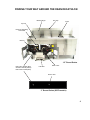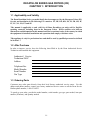
1
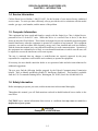
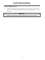
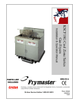
CE ONLY
*8195706*
Service Hotline 1-318-865-1711
Decathlon Series Gas Fryers (CE)
Installation & Operation Manual
D20, D50, D60 & D80 Series
Price: $10.00
819-5706
JUNE 2002
DANGER
The front ledge of the fryer is not a step. Do not stand on the fryer. Serious injury can result
from slips or contact with the hot oil.
DANGER
Do not store or use gasoline or other flammable vapors and liquids in the vicinity of this or any
other appliance.
DANGER
Instructions to be followed in the event the operator smells gas or otherwise detects a gas leak
must be posted in a prominent location. This information can be obtained from the local gas
company or gas supplier.
DANGER
The crumb tray in fryers equipped with a filter system must be emptied into a fireproof container
at the end of frying operations each day. Some food particles can spontaneously combust if left
soaking in certain shortening material. Additional information can be obtained in the filtration
manual included with the system.
WARNING
No structural material on the fryer should be altered or removed to accommodate placement of
the fryer under a hood. Questions? Call the Dean Service Hotline at 1-800-551-8633.
WARNING
Do not bang fry baskets or other utensils on the fryer’s joiner strip. The strip is present to seal
the joint between the frypot. Banging fry baskets on the strip to dislodge shortening will distort
the strip, adversely affecting its fit. It is designed for a tight fit and should only be removed for
cleaning.
IMPORTANT
Safe and satisfactory operation of Dean equipment depends upon its proper installation.
Installation MUST conform with local codes, or in the absence of local codes, to European
Community (CE) Standards.
NOTICE
IF, DURING THE WARRANTY PERIOD, THE CUSTOMER USES A PART FOR THIS ENODIS
EQUIPMENT OTHER THAN AN UNMODIFIED NEW OR RECYCLED PART PURCHASED
DIRECTLY FROM FRYMASTER/DEAN, OR ANY OF ITS AUTHORIZED SERVICE CENTERS,
AND/OR THE PART BEING USED IS MODIFIED FROM ITS ORIGINAL CONFIGURATION, THIS
WARRANTY WILL BE VOID. FURTHER, FRYMASTER/DEAN AND ITS AFFILIATES WILL NOT BE
LIABLE FOR ANY CLAIMS, DAMAGES OR EXPENSES INCURRED BY THE CUSTOMER WHICH
ARISE DIRECTLY OR INDIRECTLY, IN WHOLE OR IN PART, DUE TO THE INSTALLATION OF
ANY MODIFIED PART AND/OR PART RECEIVED FROM AN UNAUTHORIZED SERVICE CENTER.
Decathlon Series Gas Fryers (CE)
Installation & Operation Manual
TABLE OF CONTENTS
Page #
1.
INTRODUCTION
1-1
1.1
Applicability and Validity
1-1
1.2
After Purchase
1-1
1.3
Ordering Parts
1-1
1.4
Service Information
1-2
1.5
Computer Information
1-2
1.6
Safety Information
1-2
1.7
Service Personnel
1-3
2.
IMPORTANT INFORMATION
2-1
2.1
Receiving and Unpacking Equipment
2-1
2.2
General
2-1
2.3
Principles of Operation
2-2
2.4
Rating Plate
2-3
2.5
Pre-Installation
2-3
2.6
Air Supply and Ventilation
2-4
2.7
Equipment Installed at High Altitudes
2-5
2.8
Conversion of Units
2-5
3.
INSTALLATION
3-1
3.1
Installing the Fryer
3-1
3.2
Leveling the Fryer (Fryers equipped with legs only)
3-1
3.3
Installing Casters and Legs
3-2
3.4
Gas Categories
3-3
3.5
Gas Connections
3-4
3.6
Adjustments/Adaptation to Different Gases
3-7
3.7
Electrical Connections
3-11
Decathlon Series Gas Fryers (CE)
Installation & Operation Manual
TABLE OF CONTENTS (CONT.)
Page #
4.
FRYER OPERATIONS
4-1
4.1
Initial Start-up
4-1
4.2
Boil-Out Procedure
4-3
4.3
Final Preparation
4-5
5.
THERMATRON OPERATION
5-1
5.1
Operating Fryers with Thermatron Controllers
5-1
6.
PREVENTATIVE MAINTENANCE
6-1
6.1
General
6-1
7.
TROUBLESHOOTING
7-1
7.1
General
7-1
7.2
Pilot Burner Malfunction
7-1
7.3
Main Burner Malfunctions
7-2
7.4
Thermatron Calibration
7-3
7.5
Wiring Diagrams
7-4
7.6
Recommended Spare Parts
7-7
FINDING YOUR WAY AROUND THE DEAN DECATHLON
Basket Hanger
Flue Cap
Frypot
Top Cap
Electronic Operating
Thermostat
Burners
1.5” Round Drains
Drain Valve Handle (Red)
Oil Return Handle (Yellow)
Drain Flush Handle (Blue)
Filter Unit
Drain Tubes
Drain Tubes
3” Round Drains (SCFD models)
A
DECATHLON SERIES GAS FRYERS (CE)
CHAPTER 1: INTRODUCTION
1.1 Applicability and Validity
The Dean Decathlon Series gas model family has been approved by the European Union (EU)
for sale and installation in the following EU countries: AT, BE, KE, KD, ES, FI, FR, GB, IE,
IT, LU, NL, NO, PT and SE.
This manual is applicable to and valid for all Dean Decathlon gas units sold in Englishspeaking countries, including those in the European Union. Where conflicts exist between
instructions and information in this manual and local or national codes of the country in which
the equipment is installed, installation and operation shall comply with those codes.
This appliance is only for professional use and shall be used by qualified personnel as defined
in Section 1.7.
1.2 After Purchase
In order to improve service, have the following chart filled in by the Dean Authorized Service
Technician who installed this equipment.
Authorized Service
Technician/FASC
Address
Telephone/Fax
Model Number
Serial Number
Gas Type
1.3 Ordering Parts
Customers may order parts directly from their local factory authorized service center. For this
address and phone number, contact your factory authorized service center or call the Dean Service
Hotline phone number, 1-800-551-8633.
To speed up your order, provide the model number, serial number, gas type, part needed, item part
number (if known), and quantity needed.
1-1
DECATHLON SERIES GAS FRYERS (CE)
CHAPTER 1: INTRODUCTION
1.4 Service Information
Call the Dean Service Hotline, 1-800-551-8633, for the location of your nearest factory authorized
service center. To assist you more efficiently, always provide the service technician with the model
number, gas type, serial number, and the nature of the problem.
1.5 Computer Information
This equipment has been tested and found to comply with the limits for a Class A digital device,
pursuant to Part 15 of the FCC rules. While this device is a verified Class A device, it has been
shown to meet the Class B limits. These limits are designed to provide reasonable protection against
harmful interference when the equipment is operated in a commercial environment. This equipment
generates, uses and can radiate radio frequency energy and, if not installed and used in accordance
with the instruction manual, may cause harmful interference to radio communications. Operation of
the equipment in a residential area is likely to cause harmful interference in which case the user will
be required to correct the interference at his own expense.
The user is cautioned that any changes or modifications not expressly approved by the party
responsible for compliance could void the user's authority to operate the equipment.
If necessary, the user should consult the dealer or an experienced radio and television technician for
additional suggestions.
The user may find the following booklet prepared by the Federal Communications Commission
helpful: "How to Identify and Resolve Radio-TV Interference Problems". This booklet is available
from the U.S. Government Printing Office, Washington, DC 20402, Stock No. 004-000-00345-4.
1.6 Safety Information
Before attempting to operate your unit, read the instructions in this manual thoroughly.
Throughout this manual, you will find notations enclosed in double-bordered boxes similar to the
ones below.
CAUTION boxes contain information about actions or conditions that may cause or result in a
malfunction of your system.
CAUTION
Example of a CAUTION box.
1-2
DECATHLON SERIES GAS FRYERS (CE)
CHAPTER 1: INTRODUCTION
1.6 Safety Information (cont.)
WARNING boxes contain information about actions or conditions that may cause or result in
damage to your system, and which may cause your system to malfunction.
WARNING
Example of a WARNING box.
DANGER boxes contain information about actions or conditions that may cause or result in injury
to personnel, and which may cause damage to your system and/or cause your system to malfunction.
DANGER
Hot cooking oil causes severe burns. Never attempt to move a fryer containing hot
cooking oil or to transfer hot cooking oil from one container to another.
1.7 Service Personnel
1.7.1 Definitions
A. Qualified and/or Authorized Operating Personnel
1.
Qualified/authorized operating personnel are those who have carefully read the information
in this manual and have familiarized themselves with the equipment functions, or have had
previous experience with the operation of equipment covered in this manual.
B. Qualified Installation Personnel
1.
Qualified/authorized personnel are those who have carefully read the information in this
manual and have familiarized themselves with the equipment functions, or who have had
previous experience with the operation of the equipment covered in this manual.
C. Qualified Service Personnel
1.
Qualified service personnel are those who are familiar with Dean equipment and have been
authorized by Dean to perform service on Dean equipment. All authorized service
personnel are required to be equipped with a complete set of service parts manuals and stock
a minimum amount of parts for Dean equipment. A list of Dean Factory Authorized Service
Centers (FASCs) was included with the fryer when shipped from the factory. Failure to use
qualified service personnel will void the Dean warranty on your equipment.
1-3
DECATHLON SERIES GAS FRYERS (CE)
CHAPTER 2: IMPORTANT INFORMATION
2.1 Receiving and Unpacking Equipment
A. Check that the container is upright. Use an outward prying motion - no hammering - to
remove the carton. Unpack the fryer carefully and remove all accessories from the carton.
Do not discard or misplace these, as they will be needed.
B. After unpacking, immediately check the equipment for visible signs of shipping damage. If
damage has occurred, contact the carrier and file the appropriate freight claims. Do not
contact the factory. Shipping damage responsibility is between the carrier and the dealer.
If your equipment arrives damaged:
1. File claim for damages immediately, regardless of extent of damage.
2. Visible loss or damage: Be sure this is noted on the freight bill or express receipt and is
signed by the person making the delivery.
3. Concealed loss or damage: If damage is unnoticed until equipment is unpacked, notify
freight company or carrier immediately, and file a concealed damage claim. This should
be done within 15 days of date of delivery. Be sure to retain container and all packing
materials for inspection.
NOTE: Dean Does Not Assume Responsibility for Damage or Loss Incurred in Transit.
C. Frying systems with built-in filtration: Take off the filter support brace and remove the
filter pan from the cabinet.
D. Remove all plastic skin from sides, front, and doors of the fryer(s). Failure to do this prior to
initial fryer operation will make it very difficult to remove later.
2.2 General
Qualified, licensed, and/or authorized installation or service personnel only (as defined in
Section 1.7) should perform the following:
??
Installation and service on Dean equipment.
??
Conversion of this appliance from one gas type to another.
Failure to use qualified, licensed, and/or authorized installation or service personnel to install,
convert to another gas type or otherwise service this equipment will void the Dean warranty
and may result in damage to the equipment or injury to personnel.
2-1
DECATHLON SERIES GAS FRYERS (CE)
CHAPTER 2: IMPORTANT INFORMATION
2.2 General (cont.)
Where conflicts exist between instructions and information in this manual and local code or
national codes, or regulations, installation and operation shall comply with the codes or
regulations in force in the country in which the equipment is installed.
CAUTION
Building codes prohibit a fryer with its open tank of hot oil/shortening from being
installed beside an open flame of any type, including those of broilers and ranges.
Upon arrival, inspect the fryer carefully for visible or concealed damage. (See Receiving and
Unpacking Equipment in Section 2.1.)
CAUTION
Dean appliances equipped with legs are for stationary installations. Appliances
fitted with legs must be lifted during movement to avoid damage to the appliance
and bodily injury. For moveable installations, optional equipment casters must be
used. Questions? Call 1-800-551-8633.
2.2.1 Product Description
Dean Decathlon Series gas fryers are energy efficient, tube-style, gas-fired units. All units are
shipped completely assembled with accessories packed inside the frypot. All units are adjusted,
tested and inspected at the factory before shipment. Sizes, weights and input rates of all models are
listed in this manual.
NOTE: The on-site supervisor is responsible for ensuring that operators are made aware of inherent
dangers of operating a deep fat fryer, particularly aspects of oil filtration, draining, and
cleaning of the fryer.
2.3 Principles of Operation
The incoming gas flows through orifices and is mixed with air in the burners to create the correct
ratio for proper combustion. The mixture is ignited at the front end of each heat tube by the pilot
light. Internal diffusers slow the flame as it goes through the burner tube. This slower and more
turbulent flame gives much better heat transfer to the walls of the tubes, thereby heating the oil
better.
2-2
DECATHLON SERIES GAS FRYERS (CE)
CHAPTER 2: IMPORTANT INFORMATION
2.4 Rating Plate
This is attached to the inside right-hand corner of the front door panel. Information provided
includes the model and serial number of the fryer, kW/hr (BTU/hr) of the burners, outlet gas
pressure in mbars (inches W.C.) and whether the unit has natural or propane gas orifices.
DANGER
Fryers MUST be connected ONLY to the gas type identified on the attached rating
plate.
2.5 Pre-Installation
DANGER
No structural material on the fryer should be altered or removed to accommodate
placement of the fryer under a hood. Questions? Call the Frymaster/Dean Service
Hotline at 1-800-551-8633.
DANGER
Do not connect this appliance to the gas supply before reviewing all information in
this chapter.
A. General: Only licensed personnel (as defined in Section 1.7) should install any gas-fired
equipment.
1.
A manual gas shut-off valve must be installed in the gas supply line ahead of the fryers for
safety and ease of future service.
2.
Dean Decathlon Series (CE) gas fryers require 230VAC single-phase 50-hertz
(International/CE) electrical service and are equipped with a 16-3 SJT grounded flexible
power cord for a direct connection to the power supply. Amperage draw for each unit
depends on the accessories supplied with the unit/system.
B. Clearances: The fryer area must be kept free and clear of all combustibles. This unit is designcertified for the following installations:
1.
Commercial installation only (not for household use).
2.
Non-combustible floor installation equipped with factory-supplied 15-cm (6-inch) adjustable
legs or 13-cm (5-inch) casters;
2-3
DECATHLON SERIES GAS FRYERS (CE)
CHAPTER 2: IMPORTANT INFORMATION
2.5 Pre-Installation (cont.)
3.
Combustible construction with a minimum clearance of 15-cm (6-inch) side and 15-cm (6inch) rear, and equipped with factory-supplied 15-cm (6-inch) adjustable legs or 13-cm (5inch) casters.
DANGER
Local building codes prohibit a fryer with its open tank of hot oil from being installed
beside an open flame of any type, including those of broilers and ranges.
2-4
DECATHLON SERIES GAS FRYERS (CE)
CHAPTER 2: IMPORTANT INFORMATION
2.6 Air Supply and Ventilation (cont.)
F. Adequate distance must be maintained from the flue outlet of the fryer(s) to the lower edge
of the filter bank. Per NFPA Standards No. 96, a minimum of 45-cm (18-inches) should be
maintained between the flue(s) and the lower edge of the exhaust hood filter.
G. Filters and drip troughs should be part of any industrial hood, but consult local codes before
constructing and installing any hood. The duct system, the exhaust hood and the filter bank
must be cleaned on a regular basis and kept free of grease.
2.7 Equipment Installed at High Altitudes
A. The fryer input rating [kW/hr (BTU/hr)] is for elevations up to 610-m (2000 feet). For
elevations above 610-m (2000 feet), the rating should be reduced 4 percent for each
additional 305-m (1000 feet) above sea level.
B. The correct orifices are installed at the factory if operating altitude is known at time of the
customer’s order.
2.8 Conversion of Units
Pressure:
1 mbar = 10,2 mm W.C. = 0,4-inch W.C.
20 mbar = 204 mm W.C. = 8-inch W.C.
1-inch W.C. = 25,4 mm W.C. = 2,5 mbar
Heat Input:
1 kW = 3410 BTU/hr
100 BTU/hr = 0,0293 kW
Temperature:
0° Celsius = 32° Fahrenheit
Temperature in degrees Celsius = (Temperature in degrees Fahrenheit (F) – 32) x 0,555
100° Celsius = (212° Fahrenheit – 32) x 0,555
2-5
DECATHLON SERIES GAS FRYERS (CE)
CHAPTER 3: INSTALLATION
3.1
Installing the Fryer
A. Initial Installation: If the fryer is installed with legs, do not push the fryer to adjust its
position. Use a pallet or lift jack to lift the fryer slightly, then place the fryer where it is to be
installed.
B. Relocating the fryer: Remove all weight from each leg before moving a fryer with legs
installed. Do not slide the fryer on the legs.
C. If a leg becomes damaged, contact your service agent for immediate repair/replacement.
3.2 Leveling the Fryer (Fryers equipped with legs only)
A. All Installations: If the floor is uneven or has a definite slope, place the fryer on an even
platform.
B. Place a carpenter’s spirit level across the top of the fryer and level the unit both front-to-back
and side-to-side. If it is not level, the unit may not function efficiently, the oil may not drain
properly for filtering and in a line-up it may not match adjacent units.
C. Adjust to the high corner and measure with the spirit level. If floor is uneven, level the unit
with the screw adjustments on each leg (ensure minimum clearances as discussed in
Chapter 2 are maintained during the leveling procedure).
D. Re-leveling: If the fryer is moved, re-level the fryer following the above instructions.
E. The install must be reviewed at the time of installation to ensure it meets the intent of these
instructions.
CAUTION
Fryers must be at room temperature, empty of oil, and if fitted with legs, lifted during
movement to avoid damage and possible bodily injury.
DANGER
Hot shortening can cause severe burns. Avoid contact. Under all circumstances, oil
must be removed from the fryer before attempting to move it to avoid oil spills, and
the falls and severe burns that could occur. This fryer may tip and cause personal
injury if not secured in a stationary position.
3-1
DECATHLON SERIES GAS FRYERS (CE)
CHAPTER 3: INSTALLATION
3.3 Installing Casters and Legs
A. Install casters and/or legs near where the fryer is to be used, as neither is secure for long
transit. Decathlon Series (CE) gas fryers cannot be curb mounted and must be equipped
with either legs or casters provided.
B. After unpacking, use a pallet or lift jack to raise the unit before installing the casters.
C. Align the caster or leg base holes with the leg support assembly and insert bolt. Install the
washers and nut hand tight, and repeat for all four holes in caster/leg base assembly.
D. Tighten the caster/leg against the leg support assembly by using appropriate tools. Ensure
that all four bolts are evenly tightened. Tighten the bolts to 5.65 Nm (50 inch-lbs.) torque.
E. For fryers with casters, there are no built-in leveling devices. The floor where the fryers
are installed must be level.
1/4-20 x 3/4 Hex Bolt
Front Channel or
Rear Channel
Front Channel
or Rear Channel
Leg Support Assembly
Washer
1/4-20 Hex Head Locknut
Front or Rear Leg with
Mounting Plate
1/4-20 x 3/4 Hex Bolt
Adjust as needed
3-2
DECATHLON SERIES GAS FRYERS (CE)
CHAPTER 3: INSTALLATION
3.4 Gas Categories
Installation shall be made with a gas connector that complies with national and local codes.
Quick disconnect devices, if used, shall likewise comply with national and local codes.
WARNING
The fryer MUST be connected to the gas supply specified on the rating and serial
number plate located on the back of the fryer door.
WARNING
If gas odors are detected, the gas supply MUST be shut off at the main shut-off
valve. The local gas company or FASC should be contacted immediately to rectify
the problem.
Dean Decathlon Series gas fryers have obtained CE markings for countries and gas categories listed
in the table below:
Countries
BE Belgium
DE Germany
DK Denmark
ES
FR
Spain
France
GB Great Britain
Supply Pressures and Appliance
Gas (mbar)
Categories
Countries
G20
20/25
I2E (R) B
G31
37
I3P
G20
20
I2E
G31
50
I3P
G20
20
I2H
IT
G20
20
II2H3P
LU Luxembourg
G31
37 and 50
G20/G25
20/25
G31
37 and 50
G20
20
G31
37
II2ESI3P
II2H3P
GR Greece
IR
NL
PT
3-3
Ireland
Italy
The
Netherlands
Portugal
Supply Pressures and Appliance
Gas (mbar)
Categories
G20
20
G31
37 and 50
G20
20
G31
37
G20
20
G20/G25
20/25
G31
50
G25
25
G31
50
G20
20
G31
37
II2H3P
II2H3P
I2H
II2E3P
II2L3P
II2H3P
DECATHLON SERIES GAS FRYERS (CE)
CHAPTER 3: INSTALLATION
3.5 Gas Connections
DANGER
Before connecting new pipe to this appliance the pipe must be blown out thoroughly
to remove all foreign material. Foreign material in the burner and gas controls will
cause improper and dangerous operation.
A. The gas supply (service) line must be the same size or greater than the fryer inlet line. This fryer
is equipped with a 22 mm (3/4") male inlet. The gas supply line must be sized to accommodate
all the gas-fired equipment that may be connected to that gas supply. Consult your contractor,
gas company, supplier, or other knowledgeable authorities.
Recommended Gas Supply Line Sizes
Gas Types
G20 and G25
G31
Number of Fryers
2 to 3
28 mm (1")
22 mm (3/4")
1
22 mm (3/4")
15 mm (1/2")
4 or more (*)
35 mm (1-1/4")
28 mm (1")
(*) When exceeding 6 meters (18 feet) for a configuration of more than four fryers, it is necessary
to provide a 35 mm (1-1/4") rigid gas connection.
DANGER
All connections must be sealed with a joint compound suitable for the gas being
used and all connections must be tested with a solution of soapy water before
lighting any pilots.
Never use matches, candles, or any other ignition source to check for leaks. If gas
odors are detected, shut off the gas supply to the appliance at the main shut-off
valve and immediately contact the local gas company or an authorized service
agency for service.
DANGER
"Dry-firing" your unit will cause damage to the frypot and can cause a fire. Always
ensure that melted shortening, cooking oil or water is in the frypot before firing the
unit.
B. Rigid Connections: Check any installer-supplied intake pipe(s) visually and clean threading
chips, or any other foreign matter before installing into a service line. If the intake pipes are not
clear of all foreign matter, the orifices will clog when gas pressure is applied. Seal pipe joints
with a sealant resistive to G31 gas. When using thread compound on gas piping, use very small
amounts and only on male threads. Use a pipe thread compound that is not affected by the
chemical action of G31 gases. DO NOT apply thread compound to the first two pipe threads—
doing so will cause clogging of the burner orifices and control valve.
3-4
DECATHLON SERIES GAS FRYERS (CE)
CHAPTER 3: INSTALLATION
3.5 Gas Connections (cont.)
C. Manual shut-off valve: This gas service supplier-installed valve must be installed in the gas
service line ahead of the fryers in the gas stream and in a position where it can be reached
quickly in the event of an emergency.
D. Regulating Gas Pressure: The fryer and shut-off valve must be disconnected from the gas supply
during any pressure testing of the system.
1. External gas regulators are not normally required on this fryer. A safety control valve
protects the fryer against pressure fluctuations. If the incoming pressure is in excess of
3,45 kPa/35,0 mbar (½" PSI), a step-down regulator will be required.
DANGER
When pressure-testing incoming gas supply lines, disconnect the fryer from the gas
line if the test pressure is 3,45 kPa [½" PSI (14 inches W.C.)] or greater to avoid
damage to the fryer’s gas piping and gas valve(s).
E. Manifold Pressure: Your local service technician should check the manifold pressure with a
manometer.
1. Check the rating plate for manifold gas pressures. G20-G25 gas units normally require
10,0 mbar, and G31 units normally require 27,5-mbar gas pressure.
2. Confirm that the arrow forged into the bottom of the regulator body, which indicates
gas flow direction, is pointed downstream towards the fryers. The air vent cap is also
part of the regulator and should not be removed.
3. If a vent line from the gas pressure regulator is used, it should be installed in
accordance with local codes or in the absence of local codes, with the appropriate
national or European Community (CE) standards.
F. Regulators can be adjusted in the field, but it is recommended that they not be tampered with
unless the part is known to be out of adjustment or serious pressure fluctuations are found to
exist and can be solved no other way.
G. Only qualified service personnel should make adjustments to the regulators.
3-5
DECATHLON SERIES GAS FRYERS (CE)
CHAPTER 3: INSTALLATION
3.5 Gas Connections (cont.)
H. Orifices: The fryer can be configured to operate on any available gas. The correct safety control
valve, appropriate gas orifices, and pilot burner are installed at the factory. While the valve can
be adjusted in the field, only qualified service personnel should make any adjustments with the
proper test equipment.
1.
The following color codes indicate the type of gas to be used for each fryer and associated
components.
Gas Type
G20 and G25
G31
CE Color Code
Blue
Red
WARNING
Use a diluted soap solution to find gas leaks when making new connections.
WARNING
If gas odors are detected, the gas supply must be shut off at the main shut-off valve.
The local gas company or FASC should be contacted immediately to rectify the
problem.
I. Flexible Couplings, Connectors and Casters
1.
If the fryer is to be installed with flexible couplings and/or quick-disconnect fittings, the
installer must use a heavy-duty certified commercial flexible connector of at least 22 mm
NPT (with suitable strain-relief attachments), in compliance with local codes or in the
absence of local codes, with the appropriate national or European Community (CE)
standards. Quick-disconnect devices must comply with local codes or in the absence of
local codes, with the appropriate national or European Community (CE) standards.
2.
For an appliance equipped with casters, the installation shall be made with a connector that
complies with local codes or in the absence of local codes, with the appropriate national or
European Community (CE) standards.
3.
Under no circumstances are the connector and the quick-disconnect device, or its associated
piping to be used to limit fryer movement. A restraining bracket is provided on the appliance
structural back to prevent the unit from moving from its installed position.
WARNING
Do not attach accessories to this fryer unless fryer is secured from tipping. The
fryer may become unstable, tip over and cause injury.
3-6
DECATHLON SERIES GAS FRYERS (CE)
CHAPTER 3: INSTALLATION
3.5 Gas Connections (cont.)
4.
To limit movement of the fryer, restraints independent of the flexible coupling or connector
must be used. Clips are located on the back panel of the fryer for the attachment of
restraints.
5.
If disconnection of the restraint is necessary, the restraint must be reconnected after the fryer
has been returned to its originally installed position.
J. After hook up, bleed the gas line of air to ensure that the pilot light will ignite quickly and
evenly.
K. CE Standards: If the unit is to be installed with flexible coupling, use a commercial flexible
coupling certified as NF D 36123 (or other national standard) or a quick disconnect device
certified NF D 36124 (or other national standard).
3.6 Adjustments/Adaptation To Different Gases
WARNING
Qualified personnel MUST perform any adaptation, modification, or gas conversion,
if required. Failure to use qualified personnel will void the Dean warranty.
A. Proper operation of appliances requires operator to inspect the following adjustments in terms of:
1.
Gas inputs and pressures.
2.
Voltage and polarities of electrical power supplies.
B. Dean gas fryers are manufactured to use the type of gas and pressure specified on the rating
plate. When changing to a different gas, adaptation must be performed by qualified
personnel. Failure to use qualified personnel will void the Dean warranty.
WARNING
If gas odors are detected, the gas supply MUST be shut off at the main shut-off
valve, and the local gas company or authorized service agency contacted for
immediate service.
3-7
DECATHLON SERIES GAS FRYERS (CE)
CHAPTER 3: INSTALLATION
3.6.1 CE Specifications
3.6.1.1 Gas Types and Specifications
MODEL*
NOMINAL HEAT
INPUT- Qn
(kW)
GAS TYPE
ORIFICE SIZE
(MM)†
ORIFICE
PART NO.
ORIFICE
QTY/ COLOR
D 80 G
37,5
G20
G25
G31
2,40
2,40
1,51
810-2060
810-2060
810-2059
5/BLUE
5/BLUE
5/RED
D 60 G
37,5
G20
G25
G31
2,40
2,40
1,51
810-2060
810-2060
810-2059
5/BLUE
5/BLUE
5/RED
D 50 G
30,0
G20
G25
G31
2,40
2,40
1,51
810-2060
810-2060
810-2059
4/BLUE
4/BLUE
4/RED
D 20 G
15,0
G20
G25
G31
2,40
2,40
1,51
810-2060
810-2060
810-2059
2/BLUE
2/BLUE
2/RED
3.6.1.2 Adjustments to Different Gas Types
MODEL*
ORIFICE
GAS TYPE
SIZE (MM)†
GAS PRESSURE AT
REGULATOR
MBAR
INCH W.C.
BURNER
MARKING
PILOT
MARKING
D 80G
2,40
2,40
1,51
2,40(1)
G20
G25
G31
G25(1)
10,0
15,0
27,0
10,0(1)
4,0
6,0
10,8
4,0(1)
Blue
Blue
Red
Blue
26N
26N
16LP
26N
D 60G
2,40
2,40
1,51
G20
G25
G31
10,0
15,0
27,0
4,0
6,0
10,8
Blue
Blue
Red
26N
26N
16LP
D 50G
2,40
2,40
1,51
G20
G25
G31
10,0
15,0
27,0
4,0
6,0
10,8
Blue
Blue
Red
26N
26N
16LP
D 20G
2,40
2,40
1,51
G20
G25
G31
10,0
15,0
27,0
4,0
6,0
10,8
Blue
Blue
Red
26N
26N
16LP
*D prefix- Decathlon Series
*G suffix- gas frying system
†Orifice size listed is for fryers operating at altitudes of 2000 feet or less.
(1) The Netherlands (NL) only.
3-8
DECATHLON SERIES GAS FRYERS (CE)
CHAPTER 3: INSTALLATION
3.6.1.2 Adjustments to Different Gas Types (cont.)
NOTE: Outlet gas pressure must be adjusted strictly within the above requirements 5 to 10 minutes
after the appliance is operating.
* For controls and adjustments, please refer to "gas valve" illustration on page 3-10. (Pilot Flame
Adjustment: Turn the pilot adjustment screw clockwise/counter-clockwise until the desired flamevolume is achieved).
3.6.2 Gas Conversion Procedures
DANGER
This appliance was configured at the factory for a specific type of gas. Converting
from one gas type to another requires the installation of specific gas-conversion
components.
Switching to a different type of gas without installing the proper conversion
components may result in fire or explosion. NEVER ATTACH THIS APPLIANCE TO A
GAS SUPPLY FOR WHICH IT IS NOT CONFIGURED!
Conversion of this appliance from one type of gas to another should only be
performed by qualified, licensed, and authorized installation or service personnel, as
defined in Section 1.7 of this manual.
See page 3-10 for gas valve illustration when performing the following conversions.
When converting from G20 to G25 gas, the following procedures apply:
? ? Equipment replacement is not required.
? ? Adjust orifice gas pressure to the appropriate value listed in the tables on page 3-8 by
turning the gas valve "adjustment screw".
? ? After adjustment, replace the adjustment-screw cover.
When converting from G20 (or G25) gas to G31 propane (or vice-versa), the following procedures
apply:
? ? Burner orifices and pilot orifice MUST be replaced.
? ? Adjust orifice gas pressure to the appropriate value listed in the tables on page 3-8 by
turning the gas-valve adjustment screw.
? ? After adjustment, replace the adjustment-screw cover.
? ? Factory MUST be notified so the conversion can be documented and a new rating plate can
be sent out.
3-9
DECATHLON SERIES GAS FRYERS (CE)
CHAPTER 3: INSTALLATION
3.6.2 Gas Conversion Procedures (cont.)
When converting from G20 (20 mbar) to G25 (25 mbar), or vice-versa, or G31 (37 mbar) to G31 (50
mbar), the following procedures apply:
? ? Check pilot-adjustment and adjust as necessary.
? ? Other adjustments are not necessary.
Conversion from one gas family to another (i.e. changing from natural gas to propane) requires
special components. Obtain the necessary components using the cross-reference in Section 3.8, Gas
Conversion Components.
Conversions can only be executed by qualified, factory-authorized personnel.
Pilot flow adjustment
Thermocouple connection
CE Gas Valve
Vent tube connection
Pressure flow adjustment
OFF Button
ON Button- Pilot Gas-flow
Use the following component information to convert from natural gas to propane and vice-versa.
Natural Gas to Propane Components
Propane To Natural Gas Components
REF
DESCRIPTION
REF
DESCRIPTION
810-2400
Pilot orifice (16LP)
810-0811
Pilot orifice (26N)
810-2059
Burner orifice
(diameter: 1.51 mm)†
810-2060
Burner orifice
(diameter: 2.40 mm)†
New Rating Contact factory at time of New Rating Contact factory at time of
Plate
Plate
conversion.
conversion.
†Burner
orifices listed are for fryers operating at altitudes of 610 meters or less. For
altitudes greater than 610 meters, contact the factory for the correct orifice size.
3-10
DECATHLON SERIES GAS FRYERS (CE)
CHAPTER 3: INSTALLATION
3.7 Electrical Connections
The fryer when installed must be electrically grounded in accordance with local codes, or in the
absence of local codes, with the appropriate national or European Community (CE) standards.
DANGER
This fryer is equipped with a three-prong (grounding) plug for protection against
electrical shock and must be plugged directly into a properly grounded, three-prong
receptacle. DO NOT CUT, REMOVE, OR OTHERWISE BYPASS THE GROUNDING
PRONG ON THIS PLUG!
The rating plate and wiring diagram are located inside the front door. The fryer is equipped with a
230VAC single-phase 50-hertz system (International/CE). Do not cut or remove the ground prong
from the power cord plug. Do not attempt to use the fryer during a power outage.
DANGER
This appliance requires electrical power for operation. Place the gas control valve in
the OFF position in case of a prolonged power outage. Do not attempt to operate
this appliance during a power outage.
3-11
DECATHLON SERIES GAS FRYERS (CE)
CHAPTER 4: FRYER OPERATIONS
4.1 Initial Start-up
WARNING
The on-site supervisor is responsible for ensuring that operators are made aware of
the inherent hazards of operating a hot oil frying system, particularly the aspects of
system operation, oil filtration, draining and cleaning procedures.
Cleaning: New units are wiped clean with solvents at the factory to remove any visible signs of dirt,
oil, grease, etc. remaining from the manufacturing process, then coated lightly with oil. Before any
food preparation, wash thoroughly with hot, soapy water to remove any film residue and dust or
debris then rinse out and wipe dry. Also wash any accessories shipped with the unit. Close the drain
valve completely and remove the crumb screen covering the heating tubes. Ensure the screws
holding the thermostat and high-limit control sensing bulbs into the frypot are tight.
Typical high-limit/sensor probe locations and mounting hardware.
CAUTION
Do not bang fry baskets or other utensils on the fryer’s joiner strip. The strip is
present to seal the joint between the frypot. Banging fry baskets on the strip to
dislodge shortening will distort the strip, adversely affecting its fit. It is designed for
a tight fit and should only be removed for cleaning.
DANGER
Never operate this appliance with an empty frypot. The frypot must be filled with
water or cooking oil/shortening before lighting the burners. Failure to do so will
damage the frypot and may cause a fire.
4-1
DECATHLON SERIES GAS FRYERS (CE)
CHAPTER 4: FRYER OPERATIONS
4.1.1 Pilot Lighting Procedures
Initial Pilot Lighting: All Dean fryers are tested, adjusted and calibrated to sea level conditions
before leaving the factory. Adjustments to assure proper operation of pilot may be necessary on
installation to meet local conditions, low gas pressure, differences in altitude and variations in gas
characteristics. These adjustments correct possible problems caused by rough handling or vibration
during shipment, and are to be performed only by qualified service personnel. These adjustments
are the responsibility of the customer and/or the dealer and are not covered by the Dean warranty.
The inlet pipe at the lower rear of the fryer brings incoming gas to the pilot safety control valve, then
to the pilot and main burners. The pilot is located high in the cabinet, at the base of the frypot.
WARNING
When checking for burner ignition or performance, do not get too close to the
burners. Slow ignition can cause possible flashback, increasing the potential for
facial and body burns.
Ensure that the following steps are done in sequence before lighting or re-lighting the pilot:
1. Turn off the manual shut-off valve on the incoming service line.
2. Turn the operating thermostat "OFF".
3. Depress the Pilot Off button (red) on the safety control valve to turn "OFF".
4. Wait at least 5 minutes for any accumulated gas to disperse.
5. Fill the frypot with oil or water to the bottom OIL LEVEL line scribed on the frypot back.
Ensure heating tubes are covered in liquid prior to engaging burners.
6. Open the manual shut-off valve on the incoming service line.
7. Apply a lighted match or taper to the pilot burner head. (If fryer is equipped with a piezo ignitor,
go to Step 8).
8. Press the white pilot light button on the gas valve and hold approximately 45 seconds to 1
minute, until the pilot stays lit. (If fryer is equipped with a piezo ignitor, press and hold the
white pilot light button, then repeatedly press the piezo ignitor button until the pilot lights.
Release the white button after approximately 45 seconds to 1 minute.)
9. If the pilot does not stay lit, depress the white pilot light button and re-light the pilot, holding the
button in longer before releasing. Trapped air may necessitate re-lighting the pilot several times
until a constant gas flow is attained.
10. When the pilot stays lit, release the white pilot light button.
11. Turn the thermostat to any "ON" setting and ensure the main burner ignites from the pilot.
4-2
DECATHLON SERIES GAS FRYERS (CE)
CHAPTER 4: FRYER OPERATIONS
4.1.2 Pilot Lighting Procedures, Electronic Ignition Systems
WARNING
Never use a match or taper to light pilot on this ignition system.
1. Turn gas "ON".
2. Turn electric power "ON" with the appropriate rocker switch or controller/computer.
3. The ignition module will energize the pilot gas supply and the ignitor. The ignitor spark will
ignite the pilot gas. The presence of the pilot flame is then proved by a flame sensor, which
sends a signal to the main gas supply, opening the valve. The operating thermostat or
computer/controller controls the fryer after ignition.
WARNING
In the event of prolonged power failure, the ignition module will shut down and lock
out the system. Turn the unit power "OFF" and them back "ON" after power has
been re-established.
4. If the pilot flame fails, the ignition module will shut down and lock out the system. To restart,
turn the electric power "OFF", wait approximately 5 minutes for the system to recycle itself, then
turn the power "ON" again. Repeat Steps 1-3.
4.2 Boil-Out Procedure
DANGER
Never leave the fryer unattended during the boil-out process. If the boil-out solution
boils over, turn the fryer off immediately and let the solution cool for a few minutes
before resuming the process. To lessen the chance of boil over, turn the fryer’s gas
valve knob to the PILOT position occasionally.
WARNING
Do not drain boil-out solution into a shortening disposal unit, a built-in filtration unit,
or a portable filter unit. These units are not intended for this purpose, and will be
damaged by the solution.
DANGER
Remove all drops of water from the frypot before filling with cooking oil or
shortening. Failure to do so will cause spattering of hot liquid when the oil or
shortening is heated to cooking temperature and may cause injury to nearby
personnel.
4-3
DECATHLON SERIES GAS FRYERS (CE)
CHAPTER 4: FRYER OPERATIONS
4.2 Boil-Out Procedure (cont.)
A. Pour cleaning solution into the frypot and add water to the bottom OIL LEVEL line scribed
in the back of the frypot.
B. Operating thermostat-equipped fryers: Set dial/temperature controller to 107ºC (225°F), just
above that of boiling water.
C. Filtration/Boil-Mode equipped fryers: Turn fryer power switch to "ON". Press the fryerreset switch (if applicable).
CAUTION
If the pilot and main burner go out, the fryer(s) MUST be left completely shut down at
least 5 minutes before lighting.
D. The main burner will ignite.
E. When the solution nears boiling point, reset the temperature controller to 93ºC (200°F).
F.
The burners should shut off just as the water starts to boil.
CAUTION
Do not leave fryer unattended. The boil-out solution may foam and overflow if fryer is
left unattended. Press ON/OFF switch to the "OFF" position (Filtration/Boil-Mode
equipped fryers) or reduce temperature (Operating Thermostat equipped fryers) to
control this condition.
G. The burners will heat the boil-out solution to a simmer. Simmer the solution for
approximately 45 minutes. Wearing protective gloves, scrub the sides of the frypot and the
tubes with the L-shaped Teflon brush, being careful not to disturb the temperature sensing
probes and the high-limit thermostat.
H. Do not allow the water level to decrease below the bottom OIL LEVEL line in frypot during
boil-out operation.
WARNING
Water or boil-out solution MUST not be allowed to drain into the filter pan or filter
system. Irreversible damage will result if water is allowed into the system.
I.
Operating Thermostat equipped fryers: After boil out is complete, turn the thermostat dial to
"OFF". Filtration/Boil-Mode equipped fryers: After boil out is complete, turn the boil out
and fryer switches to "OFF". Drain the solution from the frypot. Place a metal stockpot of
sufficient size to safely hold the entire contents of the frypot under the drain port to collect
the water/boil-out solution. Do not allow water or boil-out solution to drain into the filter
pan. The filter pump is not designed for water operation, and will be irreparably damaged
(see warning statement above).
4-4
DECATHLON SERIES GAS FRYERS (CE)
CHAPTER 4: FRYER OPERATIONS
4.2 Boil-Out Procedure (cont.)
J.
Close the drain, add fresh water (without boil-out solution) and wash all surfaces of the
frypot. Drain again.
K. Refill the frypot with fresh water and vinegar to neutralize any residual boil-out solution.
Wash all surfaces of the frypot. Drain completely and wipe down all surfaces of the frypot
to completely remove all water.
Computer-equipped fryers: See computer manual for boil-out programming and follow the
above procedures for boil-out.
DANGER
Do not go near the area directly over the flue outlet while the fryer is operating.
Always wear oil-proof, insulated gloves when working with the fryer filled with hot
oil.
Always drain hot oil into a metal stockpot of sufficient size to safely hold the entire
contents of the frypot.
4.3 Final Preparation
WARNING
NEVER set a complete block of solid shortening on top of heating tubes. To do so
will damage the heating tubes and frypot, and void the warranty.
4.3.1 Filling Fryer with Cooking Oil/Shortening
A. When using a liquid shortening (cooking oil), fill the fryer to the bottom OIL LEVEL line
scribed into the back of the frypot.
B. When using a solid shortening, first melt it in a suitable container, or cut it into small pieces
and pack it below the heat tubes, between the tubes and on top of the tubes, leaving no air
spaces around the tubes. Do not disturb or bend the sensing bulbs.
C. Thermatron with Melt Cycle Option Enabled: Set Thermatron to the working temperature.
The burners will cycle on approximately 5 seconds, and off for approximately 15 seconds
until the temperature reaches 66°C (150°F). The Thermatron will then switch to normal
operation.
4-5
DECATHLON SERIES GAS FRYERS (CE)
CHAPTER 4: FRYER OPERATIONS
4.3.1 Filling Fryer with Cooking Oil/Shortening (cont.)
D. Operating Thermostat: Turn the burners "ON" for about 10 seconds, "OFF" for a minute,
etc., until the shortening is melted. If you see smoke coming from the shortening while
melting this way, shorten the "ON" cycle and lengthen the "OFF" cycle. Smoke indicates
potential scorching of the shortening, which will shorten its useful life.
E. Compu-Fry Computer: Press the computer on/off switch to "ON". The burners will initially
operate in the MELT CYCLE mode until the shortening reaches 82°C (180°F). It will then
automatically switch to normal operation.
F.
When the frypot is filled and the shortening is melted, carefully replace the crumb screen
over the heat tubes. Wear oil-proof insulated gloves to avoid the potential for burn injury
when placing crumb screen in frypot.
G. Before starting operation, set the Thermatron/Operating Thermostat or program the
computer to the probable working temperature and wait for the temperature to stabilize.
For additional computer instructions, see computer manual.
4-6
DECATHLON SERIES GAS FRYERS (CE)
CHAPTER 5: THERMATRON OPERATION
5.1 Operating Fryers with Thermatron Controllers
Many Decathlon fryers use a solid-state
temperature controller, or Thermatron® controller
instead of a computer or basic thermostat. A
Thermatron system incorporates a temperaturecontrol circuit board, a potentiometer, and a
temperature probe. This system is more accurate
and more reliable than a standard thermostat, and
less expensive than a computer controller.
Various switch options are available on
Decathlon frying systems.
Two typical
configurations on current production systems are
illustrated below (switch locations will vary from
model to model).
Thermatron Temperature Controller
Configuration #1
Main Power Switch (optional): connects/disconnects primary
power; double-lighted with center position "OFF". This switch
controls two Thermatron controllers /Compu-Fry computers and/or
two back-up thermostats (optional).
Fryer Power Switch: controls power to
each individual fryer, both in Thermatron or
back-up mode.
POWER
O
F
F
O
N
BOIL OUT
O
F
F
B ON OFF ON
A
T
C
K
M OR
T
U
P MAIN POWER
C
O
M
P
U
T
E
R
O
N
High-Limit Reset Switch: located under
each individual control panel. This
switch must be manually reset if fryer
exceeds high-limit setpoint.
POWER
O
F
F
O
N
BOIL OUT
O
F
F
Filter Reset Switch [7 Amp (115VAC)
or 5 Amp (230VAC) Circuit Breaker]: this
switch is inline between the filter pump
and incoming line voltage. Ensure
power is "OFF" before resetting or
replacing.
5-1
B ON OFF ON
A
T
C
K
M OR
T
U
P MAIN POWER
C
O
M
P
U
T
E
R
O
N
Boil-Out Switch: operates only in "Thermatron" mode. When
"ON", this switch bypasses the Thermatron melt-cycle and
allows the water temperature to reach 196°F.
DECATHLON SERIES GAS FRYERS (CE)
CHAPTER 5: THERMATRON OPERATION
5.1 Operating Fryers with Thermatron Controllers (cont.)
MAIN POWER SWITCH – connects/disconnects primary power; double-lighted with center
position "OFF". One main switch controls two Thermatron controllers/Compu-Fry computers
and/or two back-up thermostats. When the Main Power Switch is in the center position, power is
removed from the two fryers controlled by the Thermatron controller/Compu-Fry computer or backup thermostats. When the Main Power Switch pressed to the right, power is supplied to the
Thermatron/Compu-Fry computer of each fryer. When pressed to the left, power is supplied to the
back-up thermostat of each fryer. The back-up thermostat should be left in the "OFF" position when
not in use (Newer fryers may not have the backup control option).
INDIVIDUAL FRYER POWER SWITCH – this switch controls power to the individual fryer,
whether the fryer is in the Thermatron/Computer mode or the back-up mode. When the power
switch is in the "ON" position, the indicator light will be lighted when calling for heat. The power
switch only removes power from the temperature control circuit (Thermatron and Back-Up
Thermostat). The power switch should be in the "OFF" position during filtering.
BOIL-OUT SWITCH – this only operates when in the Thermatron mode. When the Boil-Out
switch is "ON", it will bypass the Thermatron Melt Cycle, and allow the water temperature to reach
approximately 196°F.
HIGH-LIMIT RESET – Located under control panel. Must be manually reset if the fryer exceeds
high-limit setpoint.
FILTER RESET BREAKER (7 Amp Circuit Breaker- 120VAC or 5 Amp Circuit Breaker230VAC) – the breaker is in line between the filter switch and the pump. Ensure filter power is off
prior to resetting or replacing.
5 AMP (115VAC) or 2 AMP (230VAC) FUSE – each fryer circuit is protected by a 5 amp
(115VAC) or 2 amp (230VAC) fuse located under the control panel.
5–2
DECATHLON SERIES GAS FRYERS (CE)
CHAPTER 5: THERMATRON OPERATION
5.1 Operating Fryers with Thermatron Controllers (cont.)
Configuration #2
Fryer Power Switch: Turns fryer on
and off.
Boil-Out Switch (Optional):
operates only in "Thermatron"
mode. When "ON", this switch
by-passes the Thermatron
melt-cycle and allows the
water temperature to reach
196°F.
POWER
O
F
F
O
N
FRYER
BOIL OUT
O
F
F
Drain Reset Switch
(Optional): Resets drain
safety switch after closing
drain valve. Drain valve
must be completely closed
prior to resetting switch.
R
E
S
E
T
O
N
High-Limit Reset Breaker
(location varies according to
system): This must be
manually reset if fryer
exceeds high-limit setpoint.
Manual Filter Power Switch (if
equipped with filter system):
Connects/disconnects power to
filter pump if primary system fails.
Fryer power switch should be
"OFF" when filter is in use.
5–3
7 Amp (115VAC) or 5 Amp
(230VAC) Filter Reset
Breaker (if equipped with filter
system): Inline between the
filter pump and the filter power
switch. Ensure power is "OFF"
before resetting or replacing.
DECATHLON SERIES GAS FRYERS (CE)
CHAPTER 6: PREVENTATIVE MAINTENANCE
6.1 General
DANGER
Never attempt to clean the fryer during the cooking process or when the frypot is
filled with hot oil/shortening. If water comes in contact with oil/shortening heated to
cooking temperature, it will cause spattering of the oil/shortening, which can result
in severe burns to nearby personnel.
Any equipment works better and lasts longer when maintained properly and kept clean. Cooking
equipment is no exception. The Decathlon Series gas fryer should be kept clean during the working
day, and thoroughly cleaned at the end of each day. Below are recommendations for daily, weekly
and periodic preventative maintenance.
6.1.1 Daily
WARNING
Use a commercial grade cleaner formulated to effectively clean and sanitize foodcontact surfaces. Read the directions for use and precautionary statements before
use. Particular attention must be paid to the concentration of cleaner and the length
of time the cleaner remains on the food-contact surfaces.
A. Remove and wash all removable parts.
B. Clean all exterior surfaces of the cabinet. Do not use cleaners, steel wool, or any other
abrasive material on stainless steel.
C. Filter the cooking oil and replace if necessary. The oil should be filtered more frequently
when under heavy use.
6.1.2 Weekly
A. Completely drain the oil from the fryer into a metal stockpot of sufficient size to safely hold
the entire contents of the frypot for disposal. Do not use a glass or plastic container.
B. Clean the frypot by following boil-out procedures in Chapter 4.2.
CAUTION
Never allow water to boil down and expose the heating tubes. Frypot damage will
result.
6-1
DECATHLON SERIES GAS FRYERS (CE)
CHAPTER 6: PREVENTATIVE MAINTENANCE
6.1.3 Periodic/Annual
This appliance should be inspected and adjusted periodically by qualified service personnel as part of a
regular kitchen maintenance program.
Frymaster/Dean recommends that this appliance be inspected at least annually by a Factory
Authorized Service Technician as follows:
?? Inspect the cabinet inside and out, front and rear for excessive oil build-up and/or oil migration.
?? Verify that the flue opening is not obstructed by debris or accumulations of solidified oil or shortening.
?? Verify that burners and associated components (i.e. gas valves, pilot assemblies, ignitors, etc.) are in good
condition and functioning properly. Inspect all gas connections for leaks and verify that all connections
are properly tightened.
?? Verify that the burner manifold pressure is in accordance with that specified on the appliance’s rating
plate.
?? Verify that the temperature and high-limit probes are properly connected, tightened and functioning
properly, and that mounting hardware and probe guard are present and properly installed.
?? Verify that component box components (i.e. computer/controller, transformers, relays, interface boards,
etc.) are in good condition and free from oil migration build-up and other debris. Inspect the component
box wiring and verify that connections are tight and that wiring is in good condition.
?? Verify that all safety features (i.e. drain safety switches, reset switches, etc.) are present and functioning
properly.
?? Verify that the frypot/cookpot is in good condition and free of leaks and that the frypot/cookpot insulation
is in serviceable condition. Verify that the frypot tube diffusers are present and in good condition (i.e. no
visible deterioration or damage).
?? Verify that wiring harnesses and connections are tight and in good condition.
6.1.4 Stainless Steel Care
WARNING
DO NOT let water splash into the tank of hot oil. It will splatter and can cause severe
burns.
All stainless steel fryer cabinet parts should be wiped regularly with hot, soapy water during the day, and with
a liquid cleanser designed for stainless steel at the end of each day.
A. Do not use steel wool, abrasive cloths, cleansers or powders.
B. Do not use a metal knife, spatula or any other metal tool to scrape stainless steel! Scratches are
almost impossible to remove.
C. If it is necessary to scrape the stainless steel to remove any encrusted materials, soak the area first to
soften the deposit, then use a wood or nylon scraper only.
6-2
DECATHLON SERIES GAS FRYERS (CE)
CHAPTER 7: TROUBLESHOOTING
7.1 General
DANGER
Hot cooking oil/shortening will cause severe burns. Never attempt to move this
appliance when filled with hot cooking oil/shortening or to transfer hot cooking
oil/shortening from one container to another.
DANGER
This equipment should be unplugged when servicing, except when electrical circuit
tests are required. Use extreme care when performing such tests.
This appliance may have more than one electrical power supply connection point.
Disconnect all power cords before servicing.
Inspection, testing and repair of electrical components should be performed by an
authorized service agent only.
The problems and possible solutions covered are those most commonly encountered. To
troubleshoot, perform the test set-up at the beginning of each condition. Follow each step in
sequence.
7.2 Pilot Burner Malfunction
A. Pilot will not ignite; no evidence of gas at pilot burner.
1. Check that gas valve is open and gas is present at the gas valve.
2. Check pilot burner orifice for dirt or lint.
3. Authorized Service Agent Only: Remove pilot burner gas-supply line and check for
contamination; blow out if necessary, then reinstall.
B. Pilot burner ignites but will not remain lit when gas valve manual knob is released.
1. Check that thermocouple lead is properly screwed into thermocouple connection bushing
on gas valve.
2. Remove end of thermocouple lead from thermocouple connection bushing and clean with
fine sandpaper or emery cloth.
3. Authorized Service Agent Only: Pilot flame may be too high or too low. Adjust pilot
flame adjustment screw so that pilot flame extends about 19-mm (3/4-inch) above the top
of the pilot burner.
7-1
DECATHLON SERIES GAS FRYERS (CE)
CHAPTER 7: TROUBLESHOOTING
7.2 Pilot Burner Malfunction (cont.)
4. Check all connections for cleanliness and security.
C. Pilot flame of proper size, but is unstable.
thermocouple completely at all times.
Flame wavers and does not envelop the
1. Check for drafts that might be caused by air conditioning equipment or make-up air
apparatus. Turn air-moving equipment off and recheck the pilot.
7.3
Main Burner Malfunctions
A. Main burner will not come "ON"; gas not detected at main burner.
1.
Check that the gas valve is open.
2.
Check that the pilot is ignited and is operating properly.
3.
Authorized Service Agent Only: Check the high-limit switch for continuity.
4.
Authorized Service Agent Only: Check the combination gas valve and replace if
defective.
B. Main burner flames are small and appear lazy; shortening does not come up to temperature
quickly.
1.
Authorized Service Agent Only: Check gas pressure at the pressure tap of the gas valve.
Use dial type or standard water-type U-gauge manometer. With burner in operation, the
pressure should be 10 mbar (4" W.C.) for natural gas, and 27.5 mbar (11" W.C.) for
propane. If not, remove the pressure regulator adjustment cover. Use screwdriver to
turn the adjusting screw for proper pressure. Replace cover, re-check pressure and reinstall pressure tap plug.
C. Signs of excessive temperature; shortening scorches and quickly becomes discolored.
1.
Check operating thermostat. May be out of adjustment or calibration. Recalibrate if
necessary.
2.
Check gas pressure as outlined above.
3.
Shortening used is of inferior quality and/or shortening has been used too long. Replace
shortening.
4.
Ensure frypot is clean when refilling with new shortening.
7-2
DECATHLON SERIES GAS FRYERS (CE)
CHAPTER 7: TROUBLESHOOTING
7.3
Main Burner Malfunctions (cont.)
D. Fryer will not reach the temperature setting and/or runs erratically.
1.
Incorrect location of sensor probe or defective temperature sensor.
2.
Loose wiring/wire connection
E. Fryer shortening temperature cannot be controlled; fryer runs at high-limit temperature.
1.
Defective operating thermostat or temperature probe; Call Authorized Service Agent.
7.4 Thermatron Calibration
The Thermatron controller maintains a specific oil/shortening temperature through a sensing probe
mounted in the frypot. If the actual temperature of the cooking oil varies from the controller dial
setting, loosen the knob setscrew and rotate the knob until it agrees with that of the actual oil
temperature. When obtaining actual oil temperature, ensure that the thermometer is inserted within
one-inch of the frypot-mounted probe. If proper calibration cannot be achieved, contact Authorized
Service Agent for repair.
Thermatron Probe
Control Knob Setscrew (counter-set in knob)
7-3
POWERSWITCH
220 VAC
POWER
SUPPLY
Temperature
Sensor
FUSE
2 AMP
1
2
1
2
24
VAC
7-4
12 34
12 34
POT
230
VAC
13
2
14
3
7
8
9
10
11
12
1
12 3456 78 9
123456
48 OHM
RESISTOR
12 3456 78 9
24VAC
COIL
24VAC
COIL
HIGH-LIMIT
THERMOSTAT
24V "G0" SOLID STATE
TEMPERATURE CONTROLLER
DRAIN VALVE
SAFETY SWITCH
12 34 56
OPTIONAL BOILOUT
THERMOCOUPLE
SOLDER
CONNECTION
ECO
CONNECTOR
ASSEMBLY
G31 GAS
(LP GAS)
G20, G25 GAS
(NAT. GAS)
ELECTRODE
LEADWIRE
PIEZO IGNITOR
VALVE ADAPTOR
THREAD TO VALVE
GAS
VALVE
24 VAC
50 HZ
DECATHLON SERIES GAS FRYERS (CE)
CHAPTER 7: TROUBLESHOOTING
7.5 Wiring Diagrams
7.5.1 Decathlon D-50G and D-60G- Thermatron Controls- CE Only
7-5
BLK
WHT
12V
RED
240V
BLU
1
2
1
2
BLK
WHT
TRANSFORMER
(NO. 807-0979)
RED
WHT
BLU
YEL
(NOTE: 208V USE RED LEAD
240V USE BLUE LEAD.)
YEL
24V
BLK
240V
TRANSFORMER
(NO. 807-0680)
TO COMPUTER INTERFACE BOARD
TO COMPUTER
1
2
1 2 3 4 5 6 7 8 9 10 11 12 13 14 15
BLU
1 2 3 4 5 6 7 8 9 10 11 12 13 14 15
BLU
FLOAT SWITCH
COMPUTER
PUR
COMPUTER INTERFACE
BOARD (NO. 806-6336)
1
2
1 2 3 4 5 6 7 8 9
RED
YEL
RED
BLK
1 2 3 4 5 6 7 8 9 10 11 12
PUR
1 2 3 4 5 6 7 8 9
1
2
BLK
BLK
1 2 3 4 5 6 7 8 9 10 11 12
BLK
PUR
BLK
YEL
1
2
C
NO
NC
SAFETY
DRAIN SWITCH
HIGH-LIMIT
(NO. 807-3560)
BLK
THERMOCOUPLE
(NO. 810-1152)
SOLDER
CONNECTION
ECO CONNECTOR
ASSEMBLY
(NO. 2650-1)
LP GAS
(G31 GAS)
(NO. 807-2127)
NAT GAS
(G20, G25 GAS)
(NO. 807-2091)
BLK
YEL
YEL
FUSE
BLU
BLU
GND
WHT
WHT
BLK
FUSE
WHT
240 V
VALVE ADAPTOR
THREADED TO VALVE
24 VAC
50 Hz
GAS
VALVE
DECATHLON SERIES GAS FRYERS (CE)
CHAPTER 7: TROUBLESHOOTING
7.5.2 Decathlon D-50G and D-60G- Computer- CE Only
CB
BLK
WHT #2
BLK
WHT#1
8051376A
BLK #2
BLK #2
WHT #2
GRN
BY-PASS SWITCH
YEL
P1
P2
T3
T5
T2
T4
LOW VOLTAGE SHOWN
T8
CIRCUIT BREAKER
5 AMP- 230V
P/N 807-3538
230VAC
YEL
WHT
WHT
BLK
J BOX
BLU
WHT
GRN
PN 807-1420
HEAT TAPE - 25 WATT
JUCTION BOX P/N 807-3642
COVER PLATE P/N 807-3643
FUSE P/N 807-3592
FUSE HOLDER P/N 807-1321
FUSE
2 AMP
P/N 810-2100
MOTOR
24V
1 2
YEL
WHT
WHT
WHT
YEL
24V
COM
NO
NC
COM
RED
NC
NO
ADD ON ASSY
FROM LEFT
FRYER(S)
WHEN USED
OIL RETURN
LH FRYER
WHT
1 2
1 2
PUR
ORG
BLK
R1
P/N 807-3611
230V FILTER CIRCUIT
230V FILTER CIRCUIT
36" LONG LEADS
SCF OIL RETURN
TRANSFORMER/RELAY ASSY
BLOCK
P/N 810-1164
FOR CHANGE OF ROTATION INTERCHANGE
LEADS T5 AND T8 ON MOTOR
P1
T8
T3
T5
P2
T4
T2
HIGH VOLTAGE SHOWN
AMP
CONNECT
WHT#1
1 2
1 2
BLK
ORG
T2
T1
SPST
1 2 3 4
P/N 807-2196
8" LONG LEADS
7-6
COM
RED
RED
NC
NO
MICROSWITCH
SHOWN IN OFF
POSITION
P/N 807-2104
OIL POLISHING
HOSE CONNECTION
WHEN USED
WHT
1 2
1 2
WHT
8" LONG LEADS
WHT#2
ORG
COM
RED
RED
NC
NO
ADD ON ASSY
FROM RH
FRYER(S)
WHEN USED
OIL RETURN
RH FRYER
WHT
1 2
1 2
WHT
8" LONG LEADS
OPTIONAL
POWER
SWITCH
1 2
DECATHLON SERIES GAS FRYERS (CE)
CHAPTER 7: TROUBLESHOOTING
7.5.3 UFF Filtration- Typical Wiring
DECATHLON SERIES GAS FRYERS (CE)
CHAPTER 7: TROUBLESHOOTING
7.6 Recommended Spare Parts
Commonly replaced parts in older Decathlon Series gas fryers are:
Gas Valve- G20/G25 (CE)- 807-2091
Gas Valve- G31 (CE)- 807-2127
High-Limit Thermostat- 807-3560
Thermocouple- 810-1152
Temperature Sensor Probe, Thermatron (D20, D50)- 106-1757SP
Temperature Sensor Probe, Thermatron (D60, D80)- 106-1260SP
Temperature Sensor Probe, Dean Compu-Fry Computer- 106-1541SP
Thermatron Board- 807-3722
Power Switch- 807-3574
Boil-Out Switch (6-Terminal)- 807-3579
Fryer Reset Switch (Momentary)- 807-3576
Manual Filter Power Switch- 807-3580
Ignition Module- 807-3563
Ignitor/Pilot Assembly- Natural (Includes Ignition Cable)- 106-1839SP
Ignitor/Pilot Assembly- LP- 807-1553
Ignition Cable- 807-1315
Sensor Wire- 106-1645SP
Flame Sensor- 807-1310
7-7
Dean, 8700 Line Avenue, PO Box 51000, Shreveport, Louisiana 71135-1000
Shipping Address: 8700 Line Avenue, Shreveport, Louisiana 71106
TEL 1-318-865-1711
PRINTED IN THE UNITED STATES
FAX (Parts) 1-310-327-3343
SERVICE HOTLINE
1-800-551-8633
FAX (Tech Support) 1-318-219-7135
Price: $10.00
819-5706 JUNE 2002