1
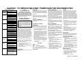
CAUTION: TO SERVICE MACHINE, POWER MUST BE DISCONNECTED!
DRYER TROUBLESHOOTING
PROBLEM
Motor runs but
drum does not
operate
Broken or loose belt
Loose motor, idler pulley, or
spring
Drum operates Drum out of shape
Worn idler pulley
but is noisy
Belt squeaking or frayed
Motor (bearing), motor pulley
loose, blower
Drum seals worn
Motor will not
stop
CAUTION
THIS MACHINE MUST BE
ELECTRICALLY GROUNDED
WHAT TO LOOK FOR
It can be grounded thru the ground lead in the 4prong power cord, if plugged into a properly grounded
appliance outlet or thru a separate No. 12 or larger
wire from the cabinet to an established ground. In all
cases, the grounding method must comply with any
local electrical code requirements.
IMPORTANT - RECONNECT ALL
GROUNDING DEVICES
Incorrect wiring
Grounded motor or wiring
Grounded heat element
Faulty timer
Open timer resistor
Motor does not Blown fuse
Timer or motor inoperative
start
Housing wiring not properly
connected to dryer
Inoperative door switch
Faulty “Push to Start” switch
Blocked or plugged lint collector,
Slow dryingimproper drying blower housing or vent pipe
Vent pipe too long
Clothes too wet when put in dryer
Dryer is overloaded
Drum set is worn or out of
position
Door gasket not sealing correctly
Control or safety thermostats
inoperative
House voltage fluctuating or low
Customer selected wrong timer
Clothes not
drying on auto- setting
Inoperative resistor
dry setting
Inoperative control thermostat
Inoperative heating element
Drum turns but Inoperative heating element
heat does not Inoperative timer
Loose terminals-tighten
come on
connections
Inoperative control or safety
thermostat
Inoperative motor switch
Broken wire in wiring harness
Element burns Worn drum seals. Replace
Connections not tight at element
out frequently
terminals
Reduced air flow. Check for
proper installation &
maintenance of duct work. (See
Installation Instructions)
ALL PARTS OF THIS APPLIANCE CAPABLE OF
CONDUCTING ELECTRICAL CURRENT ARE
GROUNDED. IF GROUNDING WIRES, SCREWS,
STRAPS, NUTS OR WASHERS USED TO
COMPLETE A PATH TO GROUND ARE REMOVED
FOR SERVICE, THEY MUST BE RETURNED TO
THEIR ORIGINAL POSITION AND PROPERLY
FASTENED.
OPERATION - DRYER
On electric model dryers, air is drawn into the heater
housing and across the open coils of the electric
heater. On gas model dryers, air is drawn into the
combustion chamber and over the burner flame. It
then is drawn through the tumbling clothes, picking up
moisture and lint. Lint is filtered out as the air passes
from the drum into the blower where it is discharged
out the vent. The air temperature is controlled by the
biased thermostat according to the setting of the fabric
selector switch. The length of the drying cycle is
controlled by the number of minutes selected on the
timer, or automatically controlled by the timer, in
conjunction with the electronic moisture sensor, for
the type of fabric selected (automatic dry cycle).
To operate the dryer, first check the lint screen and be
certain that the screen is completely free of all lint.
Place clothes in dryer and close door. (Dryer will not
operate unless door is closed.)
1.
2.
3.
Select the drying time, or automatic drying cycle,
by turning timer knob to the right.
Set drying temperature using timer for the type of
fabric being dried.
To start the dryer, turn the start knob to the right
and hold for 2 seconds.
DRUM SPEED
48-54 RPM in a counterclockwise direction as viewed
from the front.
RESISTORS
HI-LIMIT THERMOSTAT
IGNITOR
The resistor, located in the thermostat heater circuit,
causes the thermostat heater to generate varying
amounts of heat. Resistors are connected to the
timer or selector switches. Refer to the applicable
wiring diagram.
The hi-limit thermostat, single-pole, single throw switch
wired in series with the control thermostat and heat
source, is mounted to the top of the heater housing.
Should the control thermostat fail or an air blockage
occur, raising the heater housing temperature to 260°
F. on electric or 240° F. on gas.,the hi-limit thermostat
opens the circuit to the heat source and allows the
heater housing to cool down to 190° F.
To check the thermostat, remove drum. To check for
stuck contacts in the thermostat, start the dryer and
run on HIGH heat with the exhaust duct completely
blocked. The hi-limit thermostat MUST open within
three minutes.
To check for an open thermostat, remove the harness
wires from the thermostat terminals. Test for continuity.
You should have continuity through a good thermostat
at room temperature.
The ignitor is a silicon thermistor. When it attains
approximately 1800 F, the sensor (mounted on the
side of the burner tube) detectes this high radiant
heat and opens its contacts. This energizes the
secondary solenoid valve coil, allowing gas to flow
through the gas valve orifice and impinge upon the
hot glowing ignitor. The total sequence occurs within
15 to 90 seconds. The igniter is mounted to the burner
at an angle with the silicon carbide stem extended
into the flame area. The stem is very fragile and
susceptible to contamination from skin oils. HANDLE
WITH CARE by using the ignitor's insulated support.
Resistors are checked with an ohm meter and
resistor values are marked on the schematic wiring
diagram. A bad resistor will give improper drying
temperatures.
CONTROL THERMOSTAT
The thermostat and bias heater are located on the
blower housing.
CHECKING THE CONTROL
THERMOSTAT
Remove harness wires from the thermostat.
Determine the interior wiring by referring to the wiring
diagram. Use an ohm meter to check the thermostats.
1.
2.
3.
4.
Remove the exhaust venting from the rear of dryer.
Place a thermometer (pocket type reading at least
300° F.) in rear of exhaust pipe.
If dryer is installed between cabinets, making rear
access difficult, the temperature can be checked
by placing a thermocouple in the lint trap opening.
Thermocouple shall be located one inch to the
right of lint screen opening center line and extend
three inches below the top of opening.
Set timer for 30 minutes, or long enough to permit
cycling of thermostat.
Allow thermostat to cycle 3 or 4 times.
Check temperature immediately after the third or
fourth cycle of thermostat. The temperatures
(depending on the temperature setting) should
conform to those listed in the Temperature Chart.
- AT EXHAUST DUCT
OR LINT TRAP
- NO LOAD
TRIP TEMP
SETTING
HIGH
MEDIUM
LOW
145-190° F.
2-10° F. lower than high heat
2-10° F. lower than medium heat
NOTE: LONG EXTENDED VENTS AFFECT DRUM
TEMPERATURES.
SAFETY THERMOSTAT
The safety thermostat is wired in series with the motor
for ELECTRIC MODELS and the burner for GAS
MODELS. The purpose of the safety thermostat is to
shut down the dryer if the control thermostat and hilimit thermostat fail to open. Once the safety thermostat
has opened, it must be replaced. The condition that
caused it to open must be corrected.
HEATER ASSEMBLY (ELECTRIC ONLY)
The heater assembly (208/240 volts) is located behind
the drum. Perforations in the drum back allow heated
air to be drawn into the drum.
The heater is an open coil type heater made from a
continuous coil of resistance wire attached to a metal
support plate with ceramic stand offs.
Heater Assembly Testing:
1. Disconnect Laundry Center from electrical supply.
2. Remove drum.
3. Remove leads to the heater element.
4. Connect ohmmeter across heater element
terminals.
5. Check each terminal to ground.
6. If open or grounded, replace heater element.
To
1.
2.
3.
Remove or Replace Heating Element:
Disconnect Laundry Center from electrical supply.
Remove drum.
Disconnect wires from safety thermostat, hi-limit
thermostat, and ceramic insulator.
4. Remove four screws securing heating element
assembly to rear panel and remove assembly.
5. Install new heating element.
6. Reverse procedure to reassemble.
To
1.
2.
3.
test the ignitor:
Disconnect Laundry Center from electrical supply.
Remove the dryer access panel and safety cover.
Disconnect plug connector from ignitor-to-coil
harness.
4. Check resistance value of ignitor. It should be
approximately 50 to 800 Ohms depending on the
room temperature.
To
1.
2.
3.
4.
replace ignitor:
Disconnect Laundry Center from electrical supply.
Remove burner assembly.
Remove burner tube from burner assembly.
Remove the 1/4" hex head screw and washer
securing ignitor to its mounting bracket.
5. Reverse procedure to reinstall.
DOOR SWITCH
Whenever the door is opened, the door switch will
open the circuit to the motor and the external switch in
the motor will open the circuit to the heat source.
CHECKING THE MOTOR
The drive motor is 1/4 H.P., 1725 RPM with automatic
reset overload protector.
1. Disconnect electrical current and remove
ventilation panel. Remove harness wires from
motor.
2. Operate motor by connecting a properly fused
service cord to terminals 4 and 5. The motor
should start and run.
3. If motor runs, problem is open circuits in the dryer
electrical or control system. If motor does not
run, check the centrifugal switch.
4. When motor runs and the problem is NO HEAT,
check continuity between terminals 1 and 2 with
the switch button out (run position).
No continuity shows the switch is inoperative. Replace
motor.
DRYER DRIVE BELT
To
1.
2.
3.
4.
5.
6.
Remove or Replace Dryer Drive Belt:
Disconnect Laundry Center from electrical supply.
Remove front panel and air duct assembly.
Disconnect belt from idler pulley and motor pulley.
Remove belt from dryer drum.
Install new belt.
Reverse procedure to reassemble.
PART NO. 134969400A
Mauvaise sélection de
cycle par le client
Résistance défectueuse
Thermostat de contrôle défectueux
Elément chauffant défectueux
Le tambour
tourne mais
l’élément
chauffant ne
fonctionne pas
Element chauffant défectueux
Minuterie défectueuse
Bornes desserrées - resserrer les
connexions
Thermostat de contrôle ou de
sécurité défectueux
Interrupteur de moteur défectueux
Fils coupés dans le faisceau
Joints de tambour usés. Les
remplacer.
Connexions desserrées aux
L’élément brûle bornes de l’élément
fréquemment
Circulation d’air réduite. Vérifier
l’installation et l’entretien des
conduits. (Voir Instructions
d’installation)
Le cycle de
séchage
automatique
ne sèche pas
les vêtements
Filtre à charpie, boîtier de
ventilateur ou tuyau d’évacuation
d’air obstrué ou bloqué
Tuyau d’évacuation d’air trop long
Chargement de vêtements
ou linge trop mouillé
Surcharge de la sécheuse
L’ensemble de tambour
est usé ou désaligné
Mauvaise étanchéité du
joint de porte
Thermostat de contrôle
ou de sécurité défectueux
Tension d’alimentation
fluctuante ou faible
Le moteur ne
démarre pas
Séchage lent
ou incomplet
Fusible grillé
Moteur ou minuterie défectueux
Branchement incorrect au câblage
de la maison
Interrupteur de porte défectueux
Bouton-poussoir de démarrage
défectueux
Le moteur ne
s’arrête pas
Tambour déformé
Poulie folle usée
Courroie qui couine or effilochée
Moteur (roulement), poulie motrice
desserrée, ventilateur
Joints de tambour usés
Moteur, poulie folle, ou ressort mal
fixé.
Courroie brisée ou détendue
Branchement incorrect des câbles
Moteur ou câblage à la terre
Élément chauffant à la terre
Minuterie défectueuse
Résistance de minuterie infinie
Le tambour
fonctionne
mais
bruyamment
Le moteur
fonctionne
mais le
tambour ne
fonctionne pas
DÉPANNAGE SÉCHEUSE
VÉRIFIER
PROBLÈME
RÉSISTANCES
48-54 RPM dans le sens inverse des aiguilles d’une
montre, vu de l’avant.
VITESSE DE ROTATION DU TAMBOUR
Le thermostat anti-surchauffe, unipolaire, à interrupteur
unipolaire (voir SPST) branché en série avec le thermostat de contrôle et la source de chaleur est fixé à la
partie supérieure du boîtier du réchauffeur.
En cas de défectuosité du thermostat de contrôle ou de
blocage de l’évacuation d’air causant une augmentation de température du boîtier du réchauffeur à 260
degrés F. ou 240 degrés sur le gaz, le thermostat
anti-surchauffe coupe le circuit vers la source de chaleur,
permettant ainsi au boîtier du réchauffeur de se refroidir
à 190 degré F.
Pour vérifier le thermostat, démonter le tambour. Pour
vérifier le blocage éventuel des contacts du thermostat,
démarrer la sécheuse et la faire fonctionner à
température maximum (High) tout en bloquant
complètement le tuyau d’évacuation d’air. Le thermostat anti-surchauffe doit entrer en action dans les trois
minutes.
Pour vérifier que le thermostat est normalement fermé,
démonter le faisceau de fils des bornes du thermostat.
Tester la continuité qui doit normalement exister à la
température ambiante dans thermostat en bon état.
THERMOSTAT ANTI-SURCHAUFFE
1. Retirer l’orifice d’évacuation à l’arrière de la
sécheuse. Placer un thermomètre (de poche
montant au moins à 300 degrés F) à l’arrière du
tuyau d’évacuation.
L’INTÉRIEUR DU TAMBOUR.
Vérification de l’élément chauffant:
1. Débrancher l’alimentation électrique du combiné
laveuse/sécheuse.
2. Démonter le tambour.
3. Demonter les connexions de l’élément chauffant.
4. Mesurer la résistance entre les deux bornes de
l’élément chauffant.
5. Vérifier la résistance de chaque borne par rapport à
la terre.
6. Si l’élément est coupé ou mis à la terre, le remplacer.
Pour démonter ou remplacer l’élément chauffant
1. Débrancher l’alimentation électrique du combiné
laveuse/sécheuse.
2. Demonter le tambour.
3. Débrancher les fils du thermostat de sécurité, du
thermostat anti-surchauffe et des isolateurs
céramique.
4. Démonter les quatre vis fixant l’ensemble de
l’élément chauffant au panneau arrière et le déposer.
5. Installer le nouvel élément chauffant.
6. Pour le remontage, procéder en sens inverse.
L’ensemble de réchauffeur (208/240 volts) se trouve
derrière le tambour. Des perforations à l’arrière du tambour permettent à l’air réchauffé de pénétrer dans le
tambour.
Le réchauffeur est du type résistance hélicoidale
bipolaire à filament continu fixé sur une plaque de montage en métal à l’aide d’isolateurs en céramique.
ENSEMBLE DE RÉCHAUFFEUR
(ElectrqueSeulement)
Le thermostat de sécurité est câblé en série avec le
moteur pour APPAREILS ÉLECTRIQUES et avec le
brûleur pour MODÈLES AU GAZ. Il a pour rôle d’arrêter
la sécheuse si le thermostat de contrôle et le thermostat
anti-surchauffe ne coupent pas le circuit. Le thermostat
de sécurité doit être remplacé après chaque activation.
Il faut remédier à la situation qui a causé son
déclenchement.
Démonter le faisceau de fils du thermostat. Déterminer
les connexions d’après schéma de câblage. Utiliser
un ohmmètre pour vérifier le thermostat.
THERMOSTAT DE SÉCURITÉ
VÉRIFICATION DU THERMOSTAT DE
CONTRÔLE
Le thermostat et réchauffeur de polarisation sont
situés sur le boîtier du ventilateur.
THERMOSTAT DE CONTRÔLE
L’air aspiré dans le boîtier du réchauffeur circule autour
Si la sécheuse est encastrée et rend l’accès par
des éléments du chauffage électrique. Sur des
l’arrière difficile, il est possible de vérifier la
dessiccateurs de modèle de gaz, de l'air est dessiné
température en plaçant un thermocouple dans
dans la chambre de combustion et l'excédent la
l’ouverture du filtre à charpie. Placer celui-ci un
flamme de brûleue L’air réchauffé passe ensuite dans
pouce à droite du centre de l’ouverture, et à trois
le tambour contenant les vêtements, et en retire
pouces du bors supérieur.
l’humidité et la charpie. Cette dernière est filtrée lorsque
2. Régler la minuterie à 30 minutes ou une durée
l’air passe du tambour au ventilateur qui rejette l’air par
permettant au thermostat d’entrer en action.
l’orifice d’évacuation. La température de l’air est
3. S’assurer que le thermostat fait 3 ou 4 cycles.
contrôlée par un thermostat actionné par le réglage du
4. Vérifier la température immédiatement après le
sélecteur de type de tissu. La durée du cycle de
troisième ou quatrième cycle du thermostat. Les
séchage est fonction du nombre de minutes
températures (selon le réglage de température)
sélectionnées par réglage manuel de la minuterie ou
doivent correspondre à celles qui figurent au tabest automatiquement contrôlée conjointement par la
leau des températures.
minuterie et le sonde électronique d'humidité en fonction
de la sélection du type de tissu (cycle de séchage
- A L’ORIFICE D’ÉVACUATION OU FILTRE À
automatique).
CHARPIE - SANS CHARGE
Pour faire fonctionner la sécheuse, vérifier d’abord que
le filtre à charpie n’est recouvert d’aucune charpie.
Placer les vêtements dans la sécheuse et fermer la TEMPÉRATURE D’ENCLENCHEMENT
porte. (La sécheuse ne fonctionne pas la porte ouverte.) RÉGLAGE
HAUT (HIGH)
145 - 190 degrés F
1. Sélectionner la durée de séchage désirée ou le cycle MOYEN (MEDIUM) 2 - 10 degrés F plus bas
de séchage automatique en tournant le bouton de que Haut
la minuterie vers la droite.
BAS (LOW)
2 - 10 degrés F plus bas
2. Régler le sélecteur de type de tissu en fonction du que moyen
type de tissu à sécher.
3. Démarrer la sécheuse en appuyant durant 2 NOTA: LA LONGUEUR DES CONDUITS
secondes sur le bouton de démarrage.
D’ÉVACUATION AFFECTE LA TEMPÉRATURE À
DESCRIPTION DU FONCTIONNEMENT
TOUTES LES PIÈCES DE CET APPAREIL
CONDUCTRICES DE L’ÉLECTRICITÉ SONT
MISES À LA TERRE. SI POUR L’ENTRETIEN OU
LA RÉPARATION IL EST NÉCESSAIRE DE
DÉMONTER DES FILS, CÂBLES, VIS, TRESSES,
BOULONS OU RONDELLES SERVANT À ASSURER LA CONTINUITÉ DU CIRCUIT DE MISE À
LA TERRE, CEUX-CI DOIVENT ÊTRE REMONTÉS
À LEUR EMPLACEMENT INITIAL ET SERRÉS
CORRECTEMENT.
IMPORTANT - REBRANCHER TOUS LES
DISPOSITIFS DE MISE À LA TERRE
La résistance présente dans le circuit du thermostat
du réchauffeur module le niveau de chaleur. Les
résistances sont branchées à la minuterie et aux
Il peut être mis à la terre à l’aide du fil de terre du sélecteurs. Voir le schéma de câblage approprié.
cordon d’alimentation à quatre bornes lors du
branchement à une prise pour appareil électrique On contrôle les résistances à l’aide d’un ohmmètre
elle-même correctement mise à la terre, ou à et le schéma de câblage fournit indique leur valeur.
l’aide d’un fil No.12 ou de calibre supérieur reli- Une résistance défectueuse produit un écart dans la
ant la carosserie à une prise de terre. Dans tous températures de séchage.
les cas la connexion doit respecter toutes les
exigences des codes d’électricité locaux.
AVERTISSEMENT
CET APPAREIL DOIT
ÊTRE MIS À LA TERRE
N/P134969400A
COURROIE D’ENTRAÎNEMENT DE LA SÉCHEUSE
Pour démonter ou remplacer la courroie
d’entraînement de la sécheuse :
1. Débrancher l’alimentation électrique du combiné
laveuse/sécheuse.
2. Démonter le panneau avant et l’ensemble des conduits de ventilation.
3. Sortir la courroie de la poulie folle et de la poulie
motrice.
4. Sortir la courroie du tambour de la sécheuse.
5. Installer la nouvelle courroie.
6. Pour le remontage, procéder en sens inverse.
VÉRIFICATION DU MOTEUR
Moteur de 1/4 C.V., 1725 T/M, muni d’un interrupteur de
surcharge à réenclenchement automatique.
1. Débrancher l’alimentation et démonter le panneau
de ventilation. Démonter le faisceau de fils du moteur.
2. Faire fonctionner le moteur en branchant un cordon
d’alimentation de réparation muni d’un fusible aux
bornes 4 et 5. Le moteur doit démarrer et tourner.
3. Si le moteur fonctionne, le problème est relié à des
circuits défectueux dans le circuit électrique de la
sécheuse ou dans le circuit du système de
commande. Si le moteur ne fonctionne pas, vérifier
l’interrupteur centrifuge.
4 Si le moteur tourne et qu’il n’y a pas de chauffage,
vérifier la continuité entre les bornes 1 et 2 avec le
bouton-poussoir de l’interrupteur tiré (position de
fonctionnement).
L’absence de continuité indique une défectuosité de
l’interrupteur. Remplacer le moteur.
INTERRUPTEUR DE PORTE
Lorsque la porte est ouverte, l’interrupteur de porte coupe
le circuit au moteur et l’interrupteur extérieur du moteur
coupe le circuit vers la source de chauffage.
L'ignitor est une thermistance de silicium. Quand il
atteint approximativement 1800 degrés de F., sensor
(mounted du côté des tube) detects de brûleur la
chaleur radiante élevée et ouvre ses contacts. Cesi
active l'enroulement secondaire de valve de
solénoïde, permettant au gaz de traverser l'orifice de
clapet à gaz et d'empiéter sur l'ignitor rougeoyant
chaud. Toute le ordre se produit dans 15 à 90
secondes. L'ignitor est monté au brûleur à un angle
de tige de carbure de silicium avancée au secteur de
flamme. La tige est très fragile et susceptible de la
contamination à partir des sécrétions cutanées.
Manipulez avec soin en utilisant l'appui isolé des
ignitor.
Pour examiner l'ignitor:
1. Démontez le centre de blanchisserie de l'alimentation
électrique.
2. Enlevez le panneau d'access de dessiccateur et la
couverture de sûreté.
3. Débranchez le connecteur de prise de ignitor-à-lovent
le harnais.
4. Vérifiez la valeur de résistance de l'ignitor. Ce devrait
être approximativement 50 à 800 ohms selon la
température ambiante.
Pour remplacer l'ignitor:
1. Démontez le centre de blanchisserie de l'alimentation
électrique.
2. Enlevez le brûleur.
3. Enlevez le tube de brûleur du brûleur.
4. Enlevez la vis à tête hex 1/4" et la rondelle fixant
l'ignitor à son support.
5. Procédé renversé à réinstaller.
IGNITOR
AVERTISSEMENT: DÉBRANCHER L'ALIMENTATION AVANT DE PROCÉDER À L'ENTRETIEN DE CET APPAREIL!