1
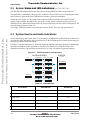
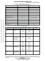
Freescale Semiconductor, Inc.
ARCHIVED BY FREESCALE SEMICONDUCTOR, INC. 2005
Freescale Semiconductor, Inc...
ARCHIVED BY FREESCALE SEMICONDUCTOR, INC. 2005
Bluetooth Headset
User’s Guide
94001480400/D
Rev. 1.5, 2002-09-02
For More Information On This Product,
Go to: www.freescale.com
Freescale Semiconductor, Inc.
ARCHIVED BY FREESCALE SEMICONDUCTOR, INC. 2005
Freescale Semiconductor, Inc...
ARCHIVED BY FREESCALE SEMICONDUCTOR, INC. 2005
Motorola reserves the right to make changes without further notice to any products herein. Motorola makes no warranty,
representation or guarantee regarding the suitability of its products for any particular purpose, nor does Motorola assume any liability
arising out of the application or use of any product or circuit, and specifically disclaims any and all liability, including without limitation
consequential or incidental damages. “Typical” parameters which may be provided in Motorola data sheets and/or specifications can
and do vary in different applications and actual performance may vary over time. All operating parameters, including “Typicals” must
be validated for each customer application by customer’s technical experts. Motorola does not convey any license under its patent
rights nor the rights of others. Motorola products are not designed, intended, or authorized for use as components in systems
intended for surgical implant into the body, or other applications intended to support life, or for any other application in which the
failure of the Motorola product could create a situation where personal injury or death may occur. Should Buyer purchase or use
Motorola products for any such unintended or unauthorized application, Buyer shall indemnify and hold Motorola and its officers,
employees, subsidiaries, affiliates, and distributors harmless against all claims, costs, damages, and expenses, and reasonable
attorney fees arising out of, directly or indirectly, any claim of personal injury or death associated with such unintended or
unauthorized use, even if such claim alleges that Motorola was negligent regarding the design or manufacture of the part. The
Bluetooth trademarks are owned by their proprietor and used by Motorola, Inc., under license. All other product or service names are
the property of their respective owners. © Motorola, Inc. 2003.
Motorola and
are registered trademarks of Motorola, Inc. Motorola, Inc. is an Equal Opportunity/Affirmative Action Employer.
How to reach us:
USA/EUROPE/Locations Not Listed: Motorola Literature Distribution; P.O. Box 5405, Denver, Colorado, 80217.
1–303–675–2140 or 1–800–441–2447
JAPAN: Motorola Japan Ltd.; SPS, Technical Information Center, 3–20–1, Minami–Azabu, Minato–ku,
Tokyo 106–8573 Japan. 81–3–3440–3569
ASIA/PACIFIC: Motorola Semiconductors H.K. Ltd., Silicon Harbour Centre, 2 Dai King Street,
Tai Po Industrial Estate, Tai Po, N.T., Hong Kong. 852–26668334
Technical Information Center: 1–800–521–6274
HOME PAGE: http://www.motorola.com/semiconductors/
For More Information On This Product,
Go to: www.freescale.com
© Copyright Motorola, Inc., 2003
Freescale Semiconductor, Inc.
ARCHIVED BY FREESCALE SEMICONDUCTOR, INC. 2005
Contents
Chapter 1
Introduction
About This Document. . . . . . . . . . . . . . . . . . . . . . . . . . . . . . . . . . . . . . . . . . . . . . . . . . . 1-1
Brief Description of Functionality . . . . . . . . . . . . . . . . . . . . . . . . . . . . . . . . . . . . . . . . . 1-1
Chapter 2
User Interface
ARCHIVED BY FREESCALE SEMICONDUCTOR, INC. 2005
Freescale Semiconductor, Inc...
1.1
1.2
2.1
2.2
2.3
Buttons . . . . . . . . . . . . . . . . . . . . . . . . . . . . . . . . . . . . . . . . . . . . . . . . . . . . . . . . . . . . . . 2-1
System States and LED Indications . . . . . . . . . . . . . . . . . . . . . . . . . . . . . . . . . . . . . . . . 2-2
System Events and Audio Indications . . . . . . . . . . . . . . . . . . . . . . . . . . . . . . . . . . . . . . 2-2
Chapter 3
System Operational Modes
3.1
3.2
3.3
3.4
3.5
3.6
3.7
3.8
Headset Power On/Connection Scan . . . . . . . . . . . . . . . . . . . . . . . . . . . . . . . . . . . . . . .
Incoming Connection . . . . . . . . . . . . . . . . . . . . . . . . . . . . . . . . . . . . . . . . . . . . . . . . . . .
Outgoing Connection . . . . . . . . . . . . . . . . . . . . . . . . . . . . . . . . . . . . . . . . . . . . . . . . . . .
Call Active (Ongoing Audio Connection) . . . . . . . . . . . . . . . . . . . . . . . . . . . . . . . . . . .
Connection Transfer . . . . . . . . . . . . . . . . . . . . . . . . . . . . . . . . . . . . . . . . . . . . . . . . . . . .
Connection Release. . . . . . . . . . . . . . . . . . . . . . . . . . . . . . . . . . . . . . . . . . . . . . . . . . . . .
Connection Loss . . . . . . . . . . . . . . . . . . . . . . . . . . . . . . . . . . . . . . . . . . . . . . . . . . . . . . .
Configuration Mode (Bonding) . . . . . . . . . . . . . . . . . . . . . . . . . . . . . . . . . . . . . . . . . . .
MOTOROLA
Contents
For More Information
On This Product,
Preliminary
Go to: www.freescale.com
3-1
3-2
3-2
3-3
3-4
3-4
3-4
3-5
iii
Freescale Semiconductor, Inc.
ARCHIVED BY FREESCALE SEMICONDUCTOR, INC. 2005
Freescale Semiconductor, Inc...
ARCHIVED BY FREESCALE SEMICONDUCTOR, INC. 2005
iv
Headset
For More Information
On This Product,
Preliminary
Go to: www.freescale.com
MOTOROLA
Freescale Semiconductor, Inc.
ARCHIVED BY FREESCALE SEMICONDUCTOR, INC. 2005
Chapter 1
Introduction
This document is the user’s guide accompanying the headset included with the Development Kit for the
Bluetooth Platform Solution from Motorola.
ARCHIVED BY FREESCALE SEMICONDUCTOR, INC. 2005
Freescale Semiconductor, Inc...
1.1 About This Document
This introduction includes a brief description of the headset functionality. The following sections describe
the user interface and system operational modes.
1.2 Brief Description of Functionality
The Development Kit headset is designed for connection to any Bluetooth device capable of assuming the
role of a Bluetooth Audio Gateway (AG) and thus supporting a very basic set of features. An AG should be
capable of establishing a data link to the headset up to and including the RFCOMM layer, as well as
establishing a voice link. However, to facilitate easy testing, the headset will not require the RFCOMM
link to be established before a SCO connection can be made.
The headset supports the full Headset profile, and can be paired with up to two AGs at a time. Any AG
may connect to the headset (incoming connection), but the headset can only connect (outgoing connection)
to the AGs to which it is paired.
When connected at the RFCOMM level, the headset repeatedly monitors the battery status and the link
quality. If either drops below programmed thresholds, audible user warnings are activated. The link quality
measure is also used to determine the voice packet type used. Normally, HV3 packets are used, but HV1
packets will be used in case of weak links.
The system state can always be observed from the two system LEDs. In addition, major system events are
visually and/or audibly indicated.
Refer to Chapter 3, “System Operational Modes,” for a thorough description of system operation.
MOTOROLA
Introduction
For More Information
On This Product,
Preliminary
Go to: www.freescale.com
1-1
Introduction
Freescale Semiconductor, Inc.
ARCHIVED BY FREESCALE SEMICONDUCTOR, INC. 2005
Freescale Semiconductor, Inc...
ARCHIVED BY FREESCALE SEMICONDUCTOR, INC. 2005
1-2
Headset
For More Information
On This Product,
Preliminary
Go to: www.freescale.com
MOTOROLA
Freescale Semiconductor, Inc.
ARCHIVED BY FREESCALE SEMICONDUCTOR, INC. 2005
Chapter 2
User Interface
ARCHIVED BY FREESCALE SEMICONDUCTOR, INC. 2005
Freescale Semiconductor, Inc...
2.1 Buttons
The headset is equipped with a user interface including three buttons, referred to as VOL+, VOL-, and BT
(Bluetooth). On the silk print of the Development Kit PCB, these buttons are designated +, -, and FUNC1
respectively. FUNC2 is never used.
The BT button is mainly used for connection management, including connection transfer1, as well as
muting the headset microphone. When an audio connection is present, the VOL+ and VOL- buttons are
used for adjusting the headset speaker volume. In Config. mode, these buttons adjust the indication
volume. When no connection exists, the BT button is used for initiating an outgoing connection to one of
the paired AGs. Either of the VOL+ and VOL- buttons initiates a connection to the other paired AG.
Pressing one of the buttons when powering up the headset enters Config. mode. In this mode, the headset
will require authentication. When successfully paired, the BD address and link key will be stored in one of
two available AG slots. The AG slot to update is selected by the button pressed at power-up: Pressing the
BT button selects slot #1, whereas pressing one of the VOL+ and VOL- buttons selects slot #2. A
successful pairing automatically exits Config. mode, or it may be done manually by pressing the BT
button.
Table 2-1 provides an overview of the way the button actions depend on the system mode.
Table 2-1. Button Overview
System Mode
Idle (not paired)
Idle (paired)
Connecting Outgoing
BT button
VOL +/- button
No function
Attempt outgoing connection to AG#1 if paired
to this. Otherwise attempt #2
Attempt outgoing connection to AG#2
if paired to this. Otherwise attempt #1
Abandon connection attempt
Linked
Send AT+CKPD=200 to AG to request link
disconnection
No function
Online
Brief press: Toggle mic. muting
Held down: Send AT+CKPD=200 to AG to
request link disconnection
In-/decrease volume by 3 dB
(repetitive, total of 16 settings)
Config
Brief press: Exit Pairable mode (entering Idle
mode), while storing indications volume setting
Held down: Reset all settings to factory default
In-/decrease indication volume by 6
dB (total of five settings)
1. Connection transfer is used to request the audio output endpoint to be moved from the phone/handset to the headset. In terms of Bluetooth
connectivity, this involves requesting a Bluetooth link (ACL&SCO) between phone and headset.
MOTOROLA
User Interface
For More Information
On This Product,
Preliminary
Go to: www.freescale.com
2-1
Freescale Semiconductor, Inc.
User Interface
ARCHIVED
BY LED
FREESCALE
SEMICONDUCTOR, INC. 2005
2.2 System States
and
Indications
The following information relates to the figure below showing LED Flash Patterns and Coherence.
The system state is indicated by either a green or a red LED. The red LED is used for indicating the battery
state exclusively, whereas the green LED indicates all other system state information.
On theleft side in Figure 2-1, all possible state transitions are shown with the associated LED flash
patterns. Each rectangle represents a time slot of two seconds, which is infinitely repeated. Green/red
indicates LED on, while white indicates LED off. The green LED is shown above the red LED pattern. The
exact ON times are listed in Table 2-2.
To the right, LED flash patterns associated with events are shown. These are only generated once.
ARCHIVED BY FREESCALE SEMICONDUCTOR, INC. 2005
Freescale Semiconductor, Inc...
2.3 System Events and Audio Indications
Several significant system events, and a few system states, are indicated by audible indications. In the case
of events, the audio indication is only played once (as for the LED indications), whereas system states are
identified by repeated audio indications.
In Table 2-3, all audio indications are listed and defined. In addition to the actual frequencies and duration,
an intuitive description of their appearance is included. This should give a good idea of how each
indication sounds since just listing the frequencies may be a little too abstract for practical purposes.
Figure 2-1. LED Flash Patterns and Coherence
SYSTEM STATES
Off
Ultra Low Bat
EVENTS
(one-shot)
Config. Mode
Config. - Very Low Bat
Conn. Scan (Idle)
Scan - Very Low Bat
Reset to Default
Outgoing Conn.
Outgoing - Very Low Bat
Pairing Success
Connected
Connected - Very Low Bat
Call Active
Call Active - Very Low Bat
(any state)
Call Active - Mute Call Active - VLB & Mute
Table 2-2. LED Indications
System States
Green ON Time
Red ON Time
Off
Off
Off
Ultra low batt.
Off
200 ms on, 800 ms off, 200 ms on
Config. mode
Solid
Off
Config. mode—batt. very low
Solid
200 ms on
Connection scan (Idle)
200 ms on
Connection scan (Idle)—batt. very low
200 ms on
2-2
Headset
For More Information
On This Product,
Preliminary
Go to: www.freescale.com
Same as green LED
MOTOROLA
Freescale Semiconductor,
Inc.
System Events and Audio Indications
ARCHIVED
BY
FREESCALE
SEMICONDUCTOR,
INC. 2005
Table
2-2.
LED Indications
(Continued)
System States
Green ON Time
Outgoing connection
500 ms on, 500 ms off, 500 ms on
Outgoing connection—batt. very low
500 ms on, 500 ms off, 500 ms on
Connected
500 ms on
Connected—batt. very low
500 ms on
Call active
1000 ms on
Call active—Tx muted
Same as green LED
1000 ms on
Same as green LED
450ms on, 100 ms off, 450 ms on
1000 ms on
Green ON Time
Red ON Time
Reset to default
5 times: (50 ms on, 100 ms off)
Off
Pairing success
5 times: (100 ms on, 200 ms off)
Off
Call active—Tx muted & batt. very low
ARCHIVED BY FREESCALE SEMICONDUCTOR, INC. 2005
Same as green LED
450ms on, 100 ms off, 450 ms on
Call active—batt. very low
Freescale Semiconductor, Inc...
Red ON Time
Events
Table 2-3. Audio Indications
Indication Name
Indicated Event
Frequency
Duration
Sound
2 kHz
off
2 kHz
200 ms
50 ms
50 ms
rep. period: 3s
dii-dip
Mute (repeated)
Tx audio (mic.)
muted
Weak link (repeated)
Link conditions poor
400 Hz
800 ms
rep. period: 5s
dooop
Battery low (repeated)
Battery completely
drained. System will
be shut down in 3
minutes without
further warning
650 Hz
off
400 Hz
100 ms
500 ms
500 ms
rep. period: 5s
dup-doop
Power on
System power on
400 Hz
off
650 Hz
off
1 kHz
150 ms
50 ms
150 ms
50 ms
400 ms
do-du-diip
Config. mode entered
Config. mode has
been entered
400 Hz
off
650 Hz
off
650 Hz
150 ms
50 ms
150 ms
50 ms
400 ms
do-du-duup
Indication level test
Test indication for
adjusting indication
level
1 kHz
100 ms
dip
MOTOROLA
User Interface
For More Information
On This Product,
Preliminary
Go to: www.freescale.com
2-3
User Interface
Freescale Semiconductor, Inc.
ARCHIVED
SEMICONDUCTOR,
INC. 2005
TableBY
2-3.FREESCALE
Audio Indications
(Continued)
ARCHIVED BY FREESCALE SEMICONDUCTOR, INC. 2005
Freescale Semiconductor, Inc...
Indication Name
Indicated Event
Frequency
Duration
Sound
Pairing complete
Successful pairing
1.3 kHz
off
2 kHz
150 ms
50 ms
350 ms
di-diip
Reset to default
All settings reset to
their factory settings
500 Hz
500 ms
doop
Ring
Incoming call
800 Hz
off
650 Hz
250 ms
50 ms
350 ms
duu-duup
Long button Press
Long button press
was registered
500 Hz
150 ms
dop
Short button Press
Short button press
was registered
1 kHz
100 ms
dip
Volume min/max
No more volume
steps available
2 kHz
500 ms
diip
Link dropped
Link was dropped.
The link conditions
must be improved,
and possibly, some
action must be
performed to
re-establish the link
1 kHz
off
1 kHz
off
1 kHz
off
1 kHz
100 ms
50 ms
100 ms
50 ms
100 ms
50 ms
100 ms
di-di-di-di
Power off
System power-down
sequence initiated
1 kHz
off
650 Hz
off
400 Hz
150 ms
50 ms
150 ms
50 ms
400 ms
di-du-dooop
2-4
Headset
For More Information
On This Product,
Preliminary
Go to: www.freescale.com
MOTOROLA
Freescale Semiconductor, Inc.
ARCHIVED BY FREESCALE SEMICONDUCTOR, INC. 2005
Chapter 3
System Operational Modes
Refer to Chapter 2, “User Interface” for an overview of the system MMI, including button action matrix
and illustrations of audible and visual system indications.
ARCHIVED BY FREESCALE SEMICONDUCTOR, INC. 2005
Freescale Semiconductor, Inc...
This section describes typical operations that the user must carry out to operate the Development Kit
headset. It is divided into a number of use situations, each focusing on an aspect of system use.
On the silk print of the Development PCB, the buttons VOL+, VOL-, BT are designated +, -, and FUNC1
respectively.
3.1 Headset Power On/Connection Scan
When turned on, the headset automatically enters discoverable and connectable mode, that is, it will
repeatedly scan for an incoming inquiry1 or connection request from other Bluetooth devices such as an
audio gateway (AG).
If the AG desires, it may repeatedly try to connect to the headset, thus connecting right away when the
headset is turned on, or it may repeatedly inquire for Bluetooth units in the vicinity, thus immediately
discovering the headset when it is turned on. Having a connection to the headset up at all times will speed
up the audio link connection process substantially, but will also reduce the battery lifetime of the headset
since the units must exchange data from time to time to maintain synchronicity. A headset LED will
indicate if a permanent (data) connection exists to the AG.
If the AG creates a permanent connection, it may employ one of the Bluetooth low-power modes
supported by the headset, that is, Hold or Sniff Mode (see the Bluetooth specification for definitions).
The battery voltage level is monitored repeatedly whenever the headset is on. When there are
approximately twenty minutes of battery time left, a large-interval recurring audio indication is started.
From this point, the user will have a varying amount of time left, depending on the present use pattern.
When the battery voltage has drained to the point where the headset is assessed to be able to run only
slightly more than ten minutes, the interval between the recurring audio indications is shortened. Exactly
five minutes after this moment, the headset will be automatically shut down in order to ensure that the
battery is never completely depleted.
NOTE:
The proper thresholds depend on the selected battery, and will have to be
adjusted by the user for optimal behavior. This feature is not yet available.
The user may power off the headset at any time. The current speech and indications volume settings will be
stored before power-off.
1. The headset only scans for so-called General inquiries (not Limited inquiries), in order to optimise the response time.
MOTOROLA
System Operational Modes
For More Information
On This Product,
Preliminary
Go to: www.freescale.com
3-1
Freescale Semiconductor, Inc.
System Operational Modes
BY FREESCALE SEMICONDUCTOR, INC. 2005
3.2 IncomingARCHIVED
Connection
The AG will usually establish a connection to the headset no later than when the AG, or the equipment to
which it is connected, initiates an outgoing or detects an incoming “call”, where call might be a connection
over the POTS2, a Voice-over-IP connection, or a mobile phone call. Regardless of whether the AG
initiates the call or detects an incoming call, the Bluetooth connection to the headset will be initiated by the
AG, and is thus referred to as an incoming connection in conformity with the BT specification (that is, the
situation is seen from the headset point-of-view).
ARCHIVED BY FREESCALE SEMICONDUCTOR, INC. 2005
Freescale Semiconductor, Inc...
It is left to the AG to decide if the user should accept the connection on the headset, or if the connection is
just added without user interaction. If the user is to be prompted for acceptance, it can either be done by
sending a specified RING command to the headset, which will then issue a ring tone in the headset, or by
sending an in-band ring tone to the headset. To repeat the alert, the AG will have to re-issue the
command/ring tone. The user can accept the prompt by pressing a button, referred to as the BT button in
the following.
The headset will allow incoming connections from any Bluetooth device, even if the BD3 addresses of one
or more specific devices are stored in the headset. Stored addresses are only used when the headset
establishes the connection (see Chapter 3.3, “Outgoing Connection” below).
If the AG requires link level security, the connection can only be accepted if the headset already holds a
link key, which will be the case if the AG address has previously been stored in the headset, and the AG at
this time requested the use of authentication. In this situation, the headset and AG are said to be bonded to
each other, and the process of establishing a bond is referred to as pairing, in Bluetooth terms. Thus, in this
situation, the process of storing the AG address in the headset is the equivalent of pairing the headset and
AG. The headset can be paired to up to two AGs at a time. Additional devices can still connect to the
headset, but without the use of authentication.
Establishing the data connection may take a couple of seconds since the AG has to scan for the headset as
the two units may not necessarily be in sync. However, the establishment of the audio connection will be
practically instantaneous. The volume setting stored when the headset was last connected is used initially.
This setting was reported to the AG when the data link was established.
When connected, the headset abstains from further page and inquiry scans (that is, enters non-discoverable
and non-connectable mode) since it is not able to connect to more than one Bluetooth device at a time. This
also saves power. The headset will then be “invisible” to other AGs, and will operate as described in
Chapter 3.4, “Call Active (Ongoing Audio Connection)”.
When an incoming connection has been established, the headset will request entering Sniff Mode, in order
to save power. The AG is free to reject this request, but the headset will not repeat the request.
3.3 Outgoing Connection
To actively start a call (phone call, Voice-over-IP connection, etc.), press any of the three headset buttons
if at least one AG BD address is stored in the headset. If only one AG address is stored, a connection is
established to this device regardless of which button was pressed. If two AG addresses are stored, pressing
the BT button establishes a connection to one of them, while pressing either VOL+ or VOL- establishes a
connection to the other.
The “Outgoing Connection” state will be indicated by the headset LED. If a connection attempt is
successful, the headset connects the required Bluetooth protocols over the baseband connection, and the
Bluetooth key-press command specified in the BT specification is sent to the AG.
2. Plain Old Telephone System, that is, an analogue phone line, etc.
3. Bluetooth Device address, a universally unique ID number identifying each Bluetooth unit.
3-2
Headset
For More Information
On This Product,
Preliminary
Go to: www.freescale.com
MOTOROLA
Freescale Semiconductor,
Inc.
Call Active (Ongoing Audio Connection)
ARCHIVED
FREESCALE
SEMICONDUCTOR,
INC. 2005
It is up to the AG to decide
the right BY
behavior
in this situation.
Possible actions include
dialing a
pre-programmed number, requesting user input via a pop-up window, or prompting the user for spoken
input for speech recognition processing. However, the AG will be expected to add a voice connection over
the established data connection at some point, in accordance with the Bluetooth specification.
The headset supports an immediate disconnect from the AG followed by reconnecting the units using an
incoming connection from the AG, should this facility be desired in order to ensure that the AG is always
master of the link during normal system use. This will give the AG total control of when to set the headset
in low power Sniff Mode. After having reversed the connection, the headset operates as if the connection
had been incoming in the first place, see Chapter 3.4, “Call Active (Ongoing Audio Connection)”. A more
elegant scheme for obtaining the same result is to perform a regular master/slave switch, which is also
supported by the headset. The headset will never request a master/slave switch on its own.
ARCHIVED BY FREESCALE SEMICONDUCTOR, INC. 2005
Freescale Semiconductor, Inc...
As if an incoming connection was established, the headset will request entering Sniff Mode in order to
save power.
3.4 Call Active (Ongoing Audio Connection)
An active call (ongoing audio connection) is indicated by the headset LED. To adjust the speaker volume,
use the VOL+ and VOL- buttons. A single press on VOL+ increases the volume one setting, holding down
the button increases the volume repetitively.
The AG may modify the headset volume setting using the VGS command specified in the Bluetooth
specification. As an example, a mobile phone can use this feature to reflect the setting of the phone speaker
volume by adjusting the headset speaker volume accordingly. Conversely, the AG is notified of any
changes in the speaker level settings due to input from the headset MMI to allow the AG to keep track of
the present settings.
To mute the headset microphone (for example, to carrying out a conversation with a colleague without
disturbing the caller), press the BT button. The activation of muting will be acknowledged through an
audible alert, which will be repeated at intervals. The user will still be able to hear the caller. Muting is not
indicated to the AG.
The link quality is monitored at intervals whenever an audio connection between headset and AG exists.
Should the link quality decrease below a specific threshold, the user is warned through an audio indication.
This action is taken both to remind the user of the reason for the degrading audio quality experienced, and
to indicate that this is a known system situation, as opposed to an unknown failure. The link quality may be
increased by the user moving closer to the AG or removing any obstacles between him and the AG. When
the link quality has been increased to a level somewhat superior to the threshold mentioned above
(hysteresis), the audio indication is stopped.
When the link quality is good, that is, few packets are lost on the link, it is desirable to use the most
compact audio transmission mode, to avoid using the entire link bandwidth. This in turn allows power
saving by powering down the radio when not receiving or transmitting. However, when the link quality
deteriorates, a more robust transmission mode is desirable. To ensure this, the headset will attempt to
switch packet type depending on the link quality. HV3 packets are used by default, but the headset will
switch to HV1 packets in case of very poor link quality.
MOTOROLA
System Operational Modes
For More Information
On This Product,
Preliminary
Go to: www.freescale.com
3-3
Freescale Semiconductor, Inc.
System Operational Modes
ARCHIVED
BY FREESCALE
SEMICONDUCTOR,
INC.
2005
The headset supports entering
Sniff Mode
while maintaining
an HV2 or HV3 link.
This
can be achieved in
one of two ways:
1. The AG accepts the Sniff request send by the headset when the data link was established,
without pulling the headset out of Sniff Mode when adding the SCO link.
2. The AG requests to put the headset in Sniff Mode when the SCO link has been established.
If during an ongoing connection the user wishes to stop using the headset, perhaps because the battery is
running low, you can do so without ending the call by transferring the audio end-point from the headset to
the AG (or the equipment to which the AG is connected). Referring to the Bluetooth specification, this is
achieved by the AG, following some sort of user action on the AG4. From the headset point-of-view, this
action is identical to releasing (that is, discontinuing) the connection, and is thus similar to the situation
described as “Connection Release”.
ARCHIVED BY FREESCALE SEMICONDUCTOR, INC. 2005
Freescale Semiconductor, Inc...
3.5 Connection Transfer
The opposite situation occurs if a user wishes to start using the headset for an already ongoing
conversation. This is achieved by pressing the BT button, and is from the headset point-of-view identical to
establishing an outgoing connection (“Outgoing Connection”). Thus, it is completely up to the AG to
distinguish between a connection transfer towards the headset and an outgoing connection establishment.
3.6 Connection Release
When a call is completed, indicate to the AG that the call may be ended. In this situation, the audio link
between AG and headset will have to be released in order to save (particularly headset) power. According
to the Bluetooth specification, the data link must also be released, and the AG is always responsible for
releasing both the audio and data link. The headset merely requests this action. The user canmanually end
the connection/call by pressing the BT button, which will result in a request being sent to the AG to end the
call.
The AG may also end the call on its own, either due to some user action on the AG, or because of other
detected events, such as the remote end hanging up.
The intention of the Bluetooth specification is that when the audio link and upper protocols are released,
there should be no further communication between the headset and AG, that is, they should be completely
disconnected. However, some AGs may want to retain a data connection in order to allow communication
between the headset and AG and speed up the audio re-connection. If this is the case, some action must be
performed on the AG to close the remaining connection down, if you want to connect the headset to a
different AG. The connection will also be automatically dropped if the headset powers off.
3.7 Connection Loss
A special case of connection release occurs when the link is not intentionally released, but is dropped due
to the headset being moved too far away from the AG, or because a considerable obstacle is introduced
between the headset and AG. Most often, the user has been warned of the degrading link quality before the
link is lost, but if the headset is moved away too quickly from the AG, or if a major obstacle is suddenly
introduced, the link quality degradation may be too sudden for the headset to give a warning.
4. According to the Bluetooth specification, the audio end-point is transferred towards the device that initiates the transfer, that is, the device
on which the user action takes place.
3-4
Headset
For More Information
On This Product,
Preliminary
Go to: www.freescale.com
MOTOROLA
Freescale Semiconductor,Configuration
Inc.
Mode (Bonding)
ARCHIVED
FREESCALE
SEMICONDUCTOR,
INC.up
2005
If the link is lost, the user
is notified BY
by an
audio indication.
The headset then cleans
all internal
connection variables, and returns to the connection scan (idle) state, as if it had just been powered up.
Thus, it will be ready for any reconnect attempt from the AG.
From time to time, the user may want to reconfigure the headset, either to change the audio indications
volume setting, or to store a new AG address in the headset to allow the headset to connect to this AG.
Since this will happen rather infrequently, the user must put the headset in a special mode, where such
actions are allowed. This is done by pressing one of the headset buttons while powering up the headset,
depending on which AG address should be stored. If the address to be used when creating an outgoing
connection by pressing the BT button is to be stored, the BT button must be pressed while powering on the
headset. If the other AG address is to be stored, either the VOL+ or VOL- button must be pressed. The
headset LED will show that the headset is in Config. mode.
ARCHIVED BY FREESCALE SEMICONDUCTOR, INC. 2005
Freescale Semiconductor, Inc...
3.8 Configuration Mode (Bonding)
To adjust the volume of audible indications such as “low battery”, the user uses the VOL+ and VOLbuttons (only while in Config. mode). For each press, an example indication is given, using the new
volume setting. Actually, it is the indication volume offset from the speaker level that is adjusted, since the
indications volume is always scaled proportionally to the present speaker volume.
When in Config. mode, the headset is both discoverable and connectable, just as when in Idle mode. If an
incoming connection is established, the headset replaces the selected AG address (if one has previously
been stored) with the address of the AG establishing the incoming connection. If the new AG address was
stored in the other AG slot already, this information is expired, to avoid having identical AG addresses
stored. The Config. mode is then automatically exited, indicated by the LED and audio. Thus, the user will
be able to tell when the address has been successfully stored.
If the AG initiates authentication while creating the connection (Security Mode 3—link level security) in
order to bond the two units together5, the headset acts as required by the Bluetooth specification during the
authentication. In order to complete this procedure, the AG must know the PIN code of the headset. This
PIN is programmed at production time and stored in non-volatile memory, and is stated in the
documentation (typically '0000'). After completing this process, both units will have derived matching
Common Link Keys, and the headset will store this key for use when connecting to and accepting
incoming connections from the AG in question. The headset user will not be able to tell from the headset
whether authentication took place since this information is irrelevant to him.
The headset will still accept connections from any AG (or other Bluetooth units), even if bonded to one or
two specific units. The bonding only satisfies the AG’s desire to certify that the headset to which it
connects is (beyond any reasonable doubt) the headset to which it was originally bonded, and to allow the
headset to establish an outgoing connection.
If the user wants to exit the Config. Mode without updating the AG information, he can press the BT
button briefly. The headset then returns to Idle mode. In this case, any previously stored AG address
information is left unchanged, while any audio indication volume change is maintained. Also, the headset
automatically exits Config. mode after three minutes.
Finally, the user may press and hold the BT button to delete all AG information and reset the speaker and
indication volume settings to factory defaults. This procedure will be indicated by an audio indication and
LED flash sequence. The headset remains in Config. mode, ready for pairing a new AG.
5. Bonding two Bluetooth units together (or pairing them) is a way of ensuring that not even an imposter unit trying to pass itself off as the AG
to which the headset is bonded, can connect to the headset, since it will not know the Link Key previously agreed upon by both the headset
and the AG which it tries to replace.
MOTOROLA
System Operational Modes
For More Information
On This Product,
Preliminary
Go to: www.freescale.com
3-5
Freescale Semiconductor, Inc.
System Operational Modes
ARCHIVED BY FREESCALE SEMICONDUCTOR, INC. 2005
Freescale Semiconductor, Inc...
ARCHIVED BY FREESCALE SEMICONDUCTOR, INC. 2005
3-6
Headset
For More Information
On This Product,
Preliminary
Go to: www.freescale.com
MOTOROLA