1
Foundry EdgeIron 4802CF
Installation Guide
2100 Gold Street
P.O. Box 649100
San Jose, CA 95164-9100
Tel 408.586.1700
Fax 408.586.1900
www.foundrynetworks.com
February 2003
Copyright © 2003 Foundry Networks, Inc. All rights reserved.
No part of this work may be reproduced in any form or by any
means – graphic, electronic or mechanical, including
photocopying, recording, taping or storage in an information
retrieval system – without prior written permission of the copyright
owner.
The trademarks, logos and service marks ("Marks") displayed
herein are the property of Foundry or other third parties. You are
not permitted to use these Marks without the prior written consent
of Foundry or such appropriate third party.
Foundry Networks, BigIron, FastIron, IronView, JetCore, NetIron,
ServerIron, TurboIron, IronWare, EdgeIron, the Iron family of
marks and the Foundry Logo are trademarks or registered
trademarks of Foundry Networks, Inc. in the United States and
other countries.
F-Secure is a trademark of F-Secure Corporation. All other
trademarks mentioned in this document are the property of their
respective owners.
COMPLIANCES
FCC - Class A
This equipment generates, uses, and can radiate radio frequency energy and, if not installed
and used in accordance with the instruction manual, may cause interference to radio
communications. It has been tested and found to comply with the limits for a Class A
computing device pursuant to Subpart B of Part 15 of FCC Rules, which are designed to
provide reasonable protection against such interference when operated in a commercial
environment. Operation of this equipment in a residential area is likely to cause interference,
in which case the user, at his own expense, will be required to take whatever measures may be
required to correct the interference. You are cautioned that changes or modifications not
expressly approved by the party responsible for compliance could void your authority to
operate the equipment.
You may use unshielded twisted-pair (UTP) cable for RJ-45 connections—Category 3 or
greater for 10 Mbps connections, Category 5 for 100 Mbps connections and Category 5, 5e,
or 6 for 1000 Mbps connections. Use 50/125 or 62.5/125 micron multimode fiber optic
cable, or 9/125 micron single-mode cable, for SFP transceiver connections.
Warnings: 1.
Wear an anti-static wrist strap or take other suitable measures to prevent
electrostatic discharge when handling this equipment.
2. When connecting this switch to a power outlet, connect the field ground
lead on the tri-pole power plug to a valid earth ground line to prevent electrical hazards.
EC Conformance Declaration - Class A
Contact Foundry Networks at:
Foundry Networks, Inc.
2100 Gold Street
P.O. Box 649100
San Jose, CA 95164-9100
This information technology equipment complies with the requirements of the Council
Directive 89/336/EEC on the Approximation of the laws of the Member States relating to
Electromagnetic Compatibility and 73/23/EEC for electrical equipment used within certain
voltage limits and the Amendment Directive 93/68/EEC. For the evaluation of the
compliance with these Directives, the following standards were applied:
RFI
Emission:
• Limit class A according to EN 55022:1998
• Limit class A for harmonic current emission according to
EN 61000-3-2/1995
• Limitation of voltage fluctuation and flicker in low-voltage supply
system according to EN 61000-3-3/1995
February 2003
© 2003 Foundry Networks, Inc.
3
EDGEIRON 4802CF INSTALLATION GUIDE
Immunity:
• Product family standard according to EN 55024:1998
• Electrostatic Discharge according to EN 61000-4-2:1995
(Contact Discharge: ±4 kV, Air Discharge: ±8 kV)
• Radio-frequency electromagnetic field according to EN 61000-4-3:1996
(80 - 1000 MHz with 1 kHz AM 80% Modulation: 3 V/m)
• Electrical fast transient/burst according to EN 61000-4-4:1995 (AC/
DC power supply: ±1 kV, Data/Signal lines: ±0.5 kV)
• Surge immunity test according to EN 61000-4-5:1995
(AC/DC Line to Line: ±1 kV, AC/DC Line to Earth: ±2 kV)
• Immunity to conducted disturbances, Induced by radio-frequency
fields: EN 61000-4-6:1996 (0.15 - 80 MHz with
1 kHz AM 80% Modulation: 3 V/m)
• Power frequency magnetic field immunity test according to
EN 61000-4-8:1993 (1 A/m at frequency 50 Hz)
• Voltage dips, short interruptions and voltage variations immunity test
according to EN 61000-4-11:1994 (>95% Reduction @10 ms, 30%
Reduction @500 ms, >95% Reduction @5000 ms)
LVD:
• EN 60950 (A1/1992; A2/1993; A3/1993; A4/1995; A11/1997)
Warning: Do not plug a phone jack connector in the RJ-45 port. This may damage this
device. Les raccordeurs ne sont pas utilisé pour le systéme téléphonique!
Industry Canada - Class A
This digital apparatus does not exceed the Class A limits for radio noise emissions from
digital apparatus as set out in the interference-causing equipment standard entitled “Digital
Apparatus,” ICES-003 of the Department of Communications.
Cet appareil numérique respecte les limites de bruits radioélectriques applicables aux appareils
numériques de Classe A prescrites dans la norme sur le matériel brouilleur: “Appareils
Numériques,” NMB-003 édictée par le ministère des Communications.
Japan VCCI Class A
4
© 2003 Foundry Networks, Inc.
February 2003
COMPLIANCES
Taiwan BSMI Class A
Australia AS/NZS 3548 (1995) - Class A
ACN 066 352010
Contact Foundry Networks at:
Foundry Networks, Inc.
2100 Gold Street
P.O. Box 649100
San Jose, CA 95164-9100
February 2003
© 2003 Foundry Networks, Inc.
5
EDGEIRON 4802CF INSTALLATION GUIDE
Safety Compliance
Warning: Fiber Optic Port Safety
CLASS I
LASER DEVICE
When using a fiber optic port, never look at the transmit laser while
it is powered on. Also, never look directly at the fiber TX port and
fiber cable ends when they are powered on.
Avertissment: Ports pour fibres optiques - sécurité sur le plan
optique
Ne regardez jamais le laser tant qu’il est sous tension. Ne regardez
jamais directement le port TX (Transmission) à fibres optiques et les
embouts de câbles à fibres optiques tant qu’ils sont sous tension.
DISPOSITIF LASER
DE CLASSE I
Warnhinweis: Faseroptikanschlüsse - Optische Sicherheit
LASERGERÄT
DER KLASSE I
Niemals ein Übertragungslaser betrachten, während dieses
eingeschaltet ist. Niemals direkt auf den Faser-TX-Anschluß und auf
die Faserkabelenden schauen, während diese eingeschaltet sind.
Underwriters Laboratories Compliance Statement
Important! Before making connections, make sure you have the correct cord set. Check it
(read the label on the cable) against the following:
Operating Voltage
120 Volts
Cord Set Specifications
UL Listed/CSA Certified Cord Set
Minimum 18 AWG
Type SVT or SJT three conductor cord
Maximum length of 15 feet
Parallel blade, grounding type attachment plug rated
15 A, 125 V
240 Volts (Europe only)
Cord Set with H05VV-F cord having three
conductors with minimum diameter of 0.75 mm2
IEC-320 receptacle
Male plug rated 10 A, 250 V
The unit automatically matches the connected input voltage. Therefore, no additional
adjustments are necessary when connecting it to any input voltage within the range marked
on the rear panel.
6
© 2003 Foundry Networks, Inc.
February 2003
COMPLIANCES
Wichtige Sicherheitshinweise (Germany)
1.
Bitte lesen Sie diese Hinweise sorgfältig durch.
2.
Heben Sie diese Anleitung für den späteren Gebrauch auf.
3.
Vor jedem Reinigen ist das Gerät vom Stromnetz zu trennen. Verwenden Sie keine
Flüssigoder Aerosolreiniger. Am besten eignet sich ein angefeuchtetes Tuch zur
Reinigung.
4.
Die Netzanschlu ßsteckdose soll nahe dem Gerät angebracht und leicht zugänglich sein.
5.
Das Gerät ist vor Feuchtigkeit zu schützen.
6.
Bei der Aufstellung des Gerätes ist auf sicheren Stand zu achten. Ein Kippen oder
Fallen könnte Beschädigungen hervorrufen.
7.
Die Belüftungsöffnungen dienen der Luftzirkulation, die das Gerät vor Überhitzung
schützt. Sorgen Sie dafür, daß diese Öffnungen nicht abgedeckt werden.
8.
Beachten Sie beim Anschluß an das Stromnetz die Anschlußwerte.
9.
Verlegen Sie die Netzanschlußleitung so, daß niemand darüber fallen kann. Es sollte
auch nichts auf der Leitung abgestellt werden.
10
Alle Hinweise und Warnungen, die sich am Gerät befinden, sind zu beachten.
11.
Wird das Gerät über einen längeren Zeitraum nicht benutzt, sollten Sie es vom
Stromnetz trennen. Somit wird im Falle einer Überspannung eine Beschädigung
vermieden.
12.
Durch die Lüftungsöffnungen dürfen niemals Gegenstände oder Flüssigkeiten in das
Gerät gelangen. Dies könnte einen Brand bzw. elektrischen Schlag auslösen.
13.
Öffnen sie niemals das Gerät. Das Gerät darf aus Gründen der elektrischen Sicherheit
nur von authorisiertem Servicepersonal geöffnet werden.
14.
Wenn folgende Situationen auftreten ist das Gerät vom Stromnetz zu trennen und von
einer qualifizierten Servicestelle zu überprüfen:
a. Netzkabel oder Netzstecker sind beschädigt.
b. Flüssigkeit ist in das Gerät eingedrungen.
c. Das Gerät war Feuchtigkeit ausgesetzt.
d. Wenn das Gerät nicht der Bedienungsanleitung entsprechend funktioniert oder Sie
mit Hilfe dieser Anleitung keine Verbesserung erzielen.
e. Das Gerät ist gefallen und/oder das Gehäuse ist beschädigt.
f. Wenn das Gerät deutliche Anzeichen eines Defektes aufweist.
15.
Zum Netzanschluß dieses Gerätes ist eine geprüfte Leitung zu verwenden. Für einen
Nennstrom bis 6 A und einem Gerätegewicht größer 3 kg ist eine Leitung nicht leichter
als H05VV-F, 3G, 0.75 mm2 einzusetzen.
Der arbeitsplatzbezogene Schalldruckpegel nach DIN 45 635 Teil 1000 beträgt 70 dB(A) oder
weniger.
February 2003
© 2003 Foundry Networks, Inc.
7
EDGEIRON 4802CF INSTALLATION GUIDE
8
© 2003 Foundry Networks, Inc.
February 2003
CONTENTS
1
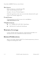
About This Guide . . . . . . . . . . . . . . . . . . . . . . . . . . . . .1-1
Audience . . . . . . . . . . . . . . . . . . . . . . . . . . . . . . . . . . . . . . . . . . . . . . . . . .
Nomenclature . . . . . . . . . . . . . . . . . . . . . . . . . . . . . . . . . . . . . . . . . . . . . .
How to Get Help . . . . . . . . . . . . . . . . . . . . . . . . . . . . . . . . . . . . . . . . . . .
Foundry Networks Technical Support . . . . . . . . . . . . . . . . . . . .
Web Access . . . . . . . . . . . . . . . . . . . . . . . . . . . . . . . . . . . . . . . . . .
E-mail Access . . . . . . . . . . . . . . . . . . . . . . . . . . . . . . . . . . . . . . . .
Telephone Access . . . . . . . . . . . . . . . . . . . . . . . . . . . . . . . . . . . . .
Warranty Coverage . . . . . . . . . . . . . . . . . . . . . . . . . . . . . . . . . . . . . . . . . .
Related Publications . . . . . . . . . . . . . . . . . . . . . . . . . . . . . . . . . . . . . . . . .
2
1-1
1-1
1-1
1-1
1-2
1-2
1-2
1-2
1-2
About the EdgeIron 4802CF . . . . . . . . . . . . . . . . . . . . 2-1
Overview . . . . . . . . . . . . . . . . . . . . . . . . . . . . . . . . . . . . . . . . . . . . . . . . . . 2-1
Switch Architecture . . . . . . . . . . . . . . . . . . . . . . . . . . . . . . . . . . . 2-2
Switching Method . . . . . . . . . . . . . . . . . . . . . . . . . . . . . . . . . 2-2
Management Options . . . . . . . . . . . . . . . . . . . . . . . . . . . . . . . . . . 2-2
Description of Hardware . . . . . . . . . . . . . . . . . . . . . . . . . . . . . . . . . . . . . 2-3
10BASE-T/100BASE-TX Ports . . . . . . . . . . . . . . . . . . . . . . . . . 2-3
1000BASE-T/SFP Ports . . . . . . . . . . . . . . . . . . . . . . . . . . . . . . . 2-3
Status LEDs . . . . . . . . . . . . . . . . . . . . . . . . . . . . . . . . . . . . . . . . . 2-4
Optional Redundant Power Unit . . . . . . . . . . . . . . . . . . . . . . . . . 2-6
Power Supply Receptacles . . . . . . . . . . . . . . . . . . . . . . . . . . . . . . 2-6
Features and Benefits . . . . . . . . . . . . . . . . . . . . . . . . . . . . . . . . . . . . . . . . 2-7
Connectivity . . . . . . . . . . . . . . . . . . . . . . . . . . . . . . . . . . . . . . . . . 2-7
Performance . . . . . . . . . . . . . . . . . . . . . . . . . . . . . . . . . . . . . . . . . 2-7
Management . . . . . . . . . . . . . . . . . . . . . . . . . . . . . . . . . . . . . . . . . 2-8
3
Network Planning . . . . . . . . . . . . . . . . . . . . . . . . . . . . 3-1
Introduction to Switching . . . . . . . . . . . . . . . . . . . . . . . . . . . . . . . . . . . .
Application Examples . . . . . . . . . . . . . . . . . . . . . . . . . . . . . . . . . . . . . . .
Collapsed Backbone . . . . . . . . . . . . . . . . . . . . . . . . . . . . . . . . . . .
Central Wiring Closet . . . . . . . . . . . . . . . . . . . . . . . . . . . . . . . . . .
Remote Connections with Fiber Cable . . . . . . . . . . . . . . . . . . . .
Making VLAN Connections . . . . . . . . . . . . . . . . . . . . . . . . . . . .
Connectivity Rules . . . . . . . . . . . . . . . . . . . . . . . . . . . . . . . . . . . . . . . . . .
February 2003
© 2003 Foundry Networks, Inc.
3-1
3-2
3-2
3-3
3-4
3-5
3-6
9
CONTENTS
1000 Mbps Gigabit Ethernet Collision Domain . . . . . . . . . . . . .
100 Mbps Fast Ethernet Collision Domain . . . . . . . . . . . . . . . .
Maximum Fast Ethernet Cable Distance . . . . . . . . . . . . . . .
10 Mbps Ethernet Collision Domain . . . . . . . . . . . . . . . . . . . . .
Maximum Ethernet Cable Distance . . . . . . . . . . . . . . . . . . .
Application Notes . . . . . . . . . . . . . . . . . . . . . . . . . . . . . . . . . . . . . . . . . .
4
Installing the Switch . . . . . . . . . . . . . . . . . . . . . . . . . . . 4-1
Selecting a Site . . . . . . . . . . . . . . . . . . . . . . . . . . . . . . . . . . . . . . . . . . . . .
Equipment Checklist . . . . . . . . . . . . . . . . . . . . . . . . . . . . . . . . . . . . . . . .
Package Contents . . . . . . . . . . . . . . . . . . . . . . . . . . . . . . . . . . . . .
Optional Rack-Mounting Equipment . . . . . . . . . . . . . . . . . . . . .
Mounting . . . . . . . . . . . . . . . . . . . . . . . . . . . . . . . . . . . . . . . . . . . . . . . . .
Rack Mounting . . . . . . . . . . . . . . . . . . . . . . . . . . . . . . . . . . . . . . .
Desktop or Shelf Mounting . . . . . . . . . . . . . . . . . . . . . . . . . . . . .
Connecting to a Power Source . . . . . . . . . . . . . . . . . . . . . . . . . . . . . . . .
5
4-1
4-2
4-2
4-2
4-3
4-3
4-5
4-6
Making Network Connections . . . . . . . . . . . . . . . . . . . 5-1
Connecting Network Devices . . . . . . . . . . . . . . . . . . . . . . . . . . . . . . . . .
Twisted-Pair Devices . . . . . . . . . . . . . . . . . . . . . . . . . . . . . . . . . . . . . . . .
Cabling Guidelines . . . . . . . . . . . . . . . . . . . . . . . . . . . . . . . . . . . .
Connecting to PCs, Servers, Hubs and Switches . . . . . . . . . . . .
Wiring Closet Connections . . . . . . . . . . . . . . . . . . . . . . . . . . . . .
A
3-6
3-7
3-7
3-7
3-7
3-8
5-1
5-1
5-1
5-2
5-3
Troubleshooting . . . . . . . . . . . . . . . . . . . . . . . . . . . . . .A-1
Diagnosing Switch Indicators . . . . . . . . . . . . . . . . . . . . . . . . . . . . . . . . . A-1
Power and Cooling Problems . . . . . . . . . . . . . . . . . . . . . . . . . . . . . . . . . A-1
Installation . . . . . . . . . . . . . . . . . . . . . . . . . . . . . . . . . . . . . . . . . . . . . . . . A-2
In-Band Access . . . . . . . . . . . . . . . . . . . . . . . . . . . . . . . . . . . . . . . . . . . . A-2
B
Cables . . . . . . . . . . . . . . . . . . . . . . . . . . . . . . . . . . . . . .B-1
Specifications . . . . . . . . . . . . . . . . . . . . . . . . . . . . . . . . . . . . . . . . . . . . . . B-1
Twisted-Pair Cable and Pin Assignments . . . . . . . . . . . . . . . . . . . . . . . . B-2
100BASE-TX/10BASE-T Pin Assignments . . . . . . . . . . . . . . . . B-3
1000BASE-T Pin Assignments . . . . . . . . . . . . . . . . . . . . . . . . . . B-4
1000BASE-T Cable Requirements . . . . . . . . . . . . . . . . . . . . . . . B-5
Cable Testing for Existing Category 5 Cable . . . . . . . . . . . . B-5
10
© 2003 Foundry Networks, Inc.
February 2003
CONTENTS
Adjusting Existing Category 5 Cabling to
Run 1000BASE-T . . . . . . . . . . . . . . . . . . . . . . . . . . . B-5
Console Port Pin Assignments . . . . . . . . . . . . . . . . . . . . . . . . . . . . . . . . B-6
DB-9 Port Pin Assignments . . . . . . . . . . . . . . . . . . . . . . . . . . . . . B-6
Console Port to 9-Pin DTE Port on PC . . . . . . . . . . . . . . . . . . . B-6
Console Port to 25-Pin DTE Port on PC . . . . . . . . . . . . . . . . . . B-7
C
Specifications . . . . . . . . . . . . . . . . . . . . . . . . . . . . . . . . C-1
Physical Characteristics . . . . . . . . . . . . . . . . . . . . . . . . . . . . . . . . . . . . . . C-1
Switch Features . . . . . . . . . . . . . . . . . . . . . . . . . . . . . . . . . . . . . . . . . . . . . C-3
Management Features . . . . . . . . . . . . . . . . . . . . . . . . . . . . . . . . . . . . . . . C-4
Standards . . . . . . . . . . . . . . . . . . . . . . . . . . . . . . . . . . . . . . . . . . . . . . . . . . C-4
Compliances . . . . . . . . . . . . . . . . . . . . . . . . . . . . . . . . . . . . . . . . . . . . . . . C-5
Glossary
Index
February 2003
© 2003 Foundry Networks, Inc.
11
CONTENTS
12
© 2003 Foundry Networks, Inc.
February 2003
CHAPTER 1
ABOUT THIS GUIDE
Audience
This guide is for system administrators with a working knowledge of
network management.
You should be familiar with switching and networking concepts.
Nomenclature
This guide uses the following typographical conventions to show
information:
Italic
highlights the title of another publication and occasionally
emphasizes a word or phrase.
code shows text that must be entered exactly as it appears in this guide.
Note: emphasizes an important fact or calls your attention to a
dependency.
How to Get Help
If you need assistance, Foundry Networks is committed to ensuring that
your investment in our products remains cost-effective by offering a
variety of support options.
Foundry Networks Technical Support
Foundry Networks technical support will ensure that the fast and easy
access that you have come to expect from your Foundry Networks
products will be maintained.
February 2003
© 2003 Foundry Networks, Inc.
1-1
EDGEIRON 4802CF INSTALLATION GUIDE
Web Access
Point your browser to the following URL:
http://www.foundrynetworks.com.
Navigate to Services/Technical Support.
Click the Login button, then enter your user name and password to gain
access to the Foundry support site.
E-mail Access
Technical requests can also be sent to the e-mail address:
[email protected]
Telephone Access
◆
1.877.TURBOCALL (887.2622): United States
◆
1.408.586.1881: Outside the United States
Warranty Coverage
Contact Foundry Networks using any of the methods listed above for
information about the standard and extended warranties.
Related Publications
Refer to the Foundry EdgeIron 4802CF User Guide for instructions on how to
configure and manage the switch.
1-2
© 2003 Foundry Networks, Inc.
February 2003
CHAPTER 2
ABOUT THE
EDGEIRON 4802CF
Overview
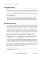
Foundry’s EdgeIron 4802CF is an intelligent Fast Ethernet switch with 48
10BASE-T/100BASE-TX ports and two 10/100/1000BASE-T combo
ports that operate in combination with 2 Small Form Factor Pluggable
(SFP) transceiver slots. This switch can easily tame your network with full
support for Spanning Tree Protocol, Multicast Switching, Virtual LANs,
and Layer 2/3/4 CoS services.
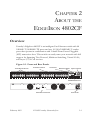
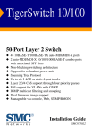
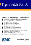
Figure 2-1. Front and Rear Panels
10/100 Mbps RJ-45 Ports
Port Status Indicators
Console Port
Mode Select Button
System Indicators
1000BASE-T/SFP Ports
Redundant Power Socket
February 2003
© 2003 Foundry Networks, Inc.
Power Socket
2-1
ABOUT THE EDGEIRON 4802CF
Switch Architecture
The EdgeIron 4802CF employs a wire-speed, non-blocking switching
fabric. This permits simultaneous wire-speed transport of multiple packets
at low latency on all ports. This switch also features full-duplex capability
on all ports, which effectively doubles the bandwidth of each connection.
Switching Method
The switch uses store-and-forward switching to ensure maximum data
integrity. With store-and-forward switching, the entire packet must be
received into a buffer and checked for validity before being forwarded.
This prevents errors from being propagated throughout the network.
Management Options
The EdgeIron 4802CF contains a comprehensive array of LEDs for “at-aglance” monitoring of network and port status. It also includes a built-in
network management agent that allows the switch to be managed in-band
using SNMP or RMON (Groups 1, 2, 3 and 9) protocols, with a Web
browser, or remotely via Telnet. The switch provides an RS-232 serial port
(DB-9 connector) on the front panel for out-of-band management. A PC
may be connected to this port for configuration and monitoring out-of
band via a null-modem cable. (See Appendix B for wiring options.)
The switch provides a wide range of advanced performance-enhancing
features. Port-based and tagged VLANs, plus support for automatic
GVRP VLAN registration and IGMP multicast filtering provide traffic
security and efficient use of network bandwidth. QoS priority queueing
ensures the minimum delay for moving real-time multimedia data across
the network. Flow control eliminates the loss of packets due to bottlenecks
caused by port saturation. Broadcast storm control prevents broadcast
traffic storms from engulfing the network.
For a detailed description of the switch’s advanced features, refer to the
Foundry EdgeIron User Guide..
2-2
© 2003 Foundry Networks, Inc.
February 2003
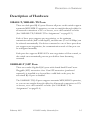
DESCRIPTION OF HARDWARE
Description of Hardware
10BASE-T/100BASE-TX Ports
These are dual-speed RJ-45 ports. Because all ports on this switch support
automatic MDI/MDI-X operation, you can use straight-through cables for
all network connections to PCs or servers, or to other switches or hubs.
(See“100BASE-TX/10BASE-T Pin Assignments” on page B-3.)
Each of these ports support auto-negotiation, so the optimum
transmission mode (half or full duplex), and data rate (10 or 100 Mbps) can
be selected automatically. If a device connected to one of these ports does
not support auto-negotiation, the communication mode of that port can
be configured manually.
Each port also supports IEEE 802.3x auto-negotiation of flow control, so
the switch can automatically prevent port buffers from becoming
saturated.
1000BASE-T/SFP Ports
These are combo Gigabit RJ-45 ports with shared Small Form Factor
Pluggable (SFP) transceiver slots. If an SFP transceiver (purchased
separately) is installed in a slot and has a valid link on the port, the
associated RJ-45 port is disabled.
The 1000BASE-T RJ-45 ports support automatic MDI/MDI-X operation,
so you can use straight-through cables for all network connections to PCs
or servers, or to other switches or hubs. (See“1000BASE-T Pin
Assignments” on page B-4.)
February 2003
© 2003 Foundry Networks, Inc.
2-3
ABOUT THE EDGEIRON 4802CF
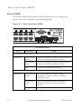
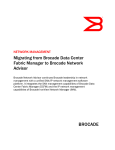
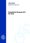
Status LEDs
The LEDs, which are located on the front panel for easy viewing, are
shown below and described in the following table.
Figure 2-2. Port and System LEDs
Port Status LEDs
LED
Condition
Status
Fast Ethernet Ports (Ports 1~48)
Link/Act.*
On/Flashing
Amber
Port has established a valid 10 Mbps network
connection. Flashing indicates activity.
On/Flashing
Green
Port has established a valid 100 Mbps network
connection. Flashing indicates activity.
Off
There is no valid link on the port.
Gigabit Ethernet Ports (Ports 49~50)
Link/Act.*
2-4
On/Flashing
Amber
Port has established a valid 10 Mbps or
100 Mbps network connection. Flashing
indicates activity.
On/Flashing
Green
Port has established a valid 1000 Mbps
network connection. Flashing indicates
activity.
Off
There is no valid link on the port.
© 2003 Foundry Networks, Inc.
February 2003
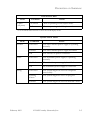
DESCRIPTION OF HARDWARE
Port Status LEDs
LED
FDX*
(all ports)
Condition
Status
On Green
Port is operating in full-duplex mode.
Off
Port is operating in half-duplex mode.
*Use the Mode Select button to select the LED display mode.
System Status LEDs
LED
Power
RPU
Diag.
February 2003
Condition
Status
On Green
The unit’s internal power supply is operating
normally.
On Red
The unit’s internal power supply has failed.
Off
The unit has no power connected.
On Green
The redundant power supply is operating
normally.
On Red
The redundant power supply has failed.
Off
No redundant power supply is connected.
On Green
The system diagnostic test has completed
successfully.
Flashing
Green
The system diagnostic test is in progress.
On Red
The system diagnostic test has detected a fault.
© 2003 Foundry Networks, Inc.
2-5
ABOUT THE EDGEIRON 4802CF
Optional Redundant Power Unit
Foundry provides an optional Redundant Power Unit (RPU) that can
supply power to the switch in the event of failure of the internal power
supply.
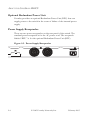
Power Supply Receptacles
There are two power receptacles on the rear panel of the switch. The
standard power receptacle is for the AC power cord. The receptacle
labeled “RPU” is for the optional Redundant Power Unit (RPU).
Figure 2-3. Power Supply Receptacles
2-6
© 2003 Foundry Networks, Inc.
February 2003
FEATURES AND BENEFITS
Features and Benefits
Connectivity
◆
48 dual-speed ports for easy Fast Ethernet integration and for
protection of your investment in legacy LAN equipment
◆
Two 10/100/1000BASE-T auto-sensing Gigabit Ethernet switching ports
that operate in combination with two Small Form Factor Pluggable (SFP)
transceiver slots
◆
Auto-negotiation enables each RJ-45 port to automatically select the
optimum communication mode (half or full duplex) if this feature is
supported by the attached device; otherwise the port can be configured
manually
◆
Independent RJ-45 10BASE-T/100BASE-TX ports with support for
auto MDI/MDI-X
◆
Unshielded (UTP) cable supported on all RJ-45 ports: Category 3, 4 or
5 for 10 Mbps connections, Category 5 for 100 Mbps connections, and
Category 5, 5e, or 6 for 1000 Mbps connections
◆
IEEE 802.3u, IEEE 802.3z, and IEEE 802.3ab compliant
Performance
◆
Transparent bridging
◆
Provides Store-and-Forward switching
◆
Supports flow control, using back pressure for half duplex and IEEE
802.3x for full duplex
◆
Auto MDI/MDIX support for the 10/100/1000BASE-T ports
◆
Up to 8K-entry, media access control (MAC) address cache
◆
Broadcast storm control
February 2003
© 2003 Foundry Networks, Inc.
2-7
ABOUT THE EDGEIRON 4802CF
◆
Includes support for an optional Redundant Power Unit
◆
Desktop or rack-mountable
Management
2-8
◆
“At-a-glance” LEDs for easy troubleshooting
◆
Network management agent:
•
Supports Telnet, SNMP/RMON and Web-based interface
•
Supports out-of-band RS-232 console port (VT100)
•
Software upload via TFTP
•
Supports BOOTP and DHCP for IP address assignment
•
Spanning Tree Protocol
•
Support for up to 255 IEEE 802.1Q based tagged VLANs with
GVRP
•
IEEE 802.1p Class of Service (CoS) through four priority queues
for each port with Weighted Round Robin queueing
•
Layer 3/4 traffic prioritization with IP Precedence and IP DSCP
•
Multicast switching based on IGMP (Internet Group
Management Protocol) snooping and multicast filtering
•
Support for up to six static or dynamic IEEE 802.3ad aggregated
trunks per switch
© 2003 Foundry Networks, Inc.
February 2003
CHAPTER 3
NETWORK PLANNING
Introduction to Switching
A network switch allows simultaneous transmission of multiple packets via
non-crossbar switching. This means that it can partition a network more
efficiently than bridges or routers. The switch has, therefore, been
recognized as one of the most important building blocks for today’s
networking technology.
When performance bottlenecks are caused by congestion at the network
access point (such as the network card for a high-volume file server), the
device experiencing congestion (server, power user or hub) can be attached
directly to a switched port. And, by using full-duplex mode, the bandwidth
of the dedicated segment can be doubled to maximize throughput.
When networks are based on repeater (hub) technology, the maximum
distance between end stations is limited. For Ethernet, there may be up to
four hubs between any pair of stations; for Fast Ethernet, the maximum is
two. This is known as the hop count. However, a switch turns the hop
count back to zero, so subdividing the network into smaller and more
manageable segments, and linking them to the larger network by means of
a switch, removes this limitation.
A switch can be easily configured in any Ethernet or Fast Ethernet
network to significantly boost bandwidth while using conventional cabling
and network cards.
February 2003
© 2003 Foundry Networks, Inc.
3-1
NETWORK PLANNING
Application Examples
The EdgeIron 4802CF is not only designed to segment your network, but
also to provide a wide range of options in setting up network connections.
Some typical applications are described below.
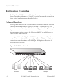
Collapsed Backbone
The EdgeIron 4802CF is an excellent choice for mixed Ethernet and Fast
Ethernet installations where significant growth is expected in the near
future. You can easily build on this basic configuration, adding direct fullduplex connections to workstations or servers. When the time comes for
further expansion, just cascade the EdgeIron 4802CF to an Ethernet or
Fast Ethernet hub or switch.
In the figure below, the EdgeIron 4802CF is operating as a collapsed
backbone for a small LAN. It is providing dedicated 10 Mbps full-duplex
connections to workstations and 100 Mbps full-duplex connections to
power users and servers.
Figure 3-1. Collapsed Backbone
...
Servers
100 Mbps
Full Duplex
3-2
...
Workstations
100 Mbps
Full Duplex
© 2003 Foundry Networks, Inc.
...
Workstations
10 Mbps
Full Duplex
February 2003
APPLICATION EXAMPLES
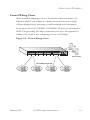
Central Wiring Closet
With 50 parallel bridging ports (i.e., 50 distinct collision domains), the
EdgeIron 4802CF can collapse a complex network down into a single
efficient bridged node, increasing overall bandwidth and throughput.
In the figure below, the 10BASE-T/100BASE-TX ports on the EdgeIron
4802CF are providing 100 Mbps connectivity for up to 48 segments. In
addition, the switch is also connecting servers at 200 Mbps.
Figure 3-2. Central Wiring Closet
Server Farm
10/100 Mbps Segments
...
February 2003
...
© 2003 Foundry Networks, Inc.
3-3
NETWORK PLANNING
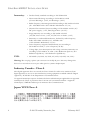
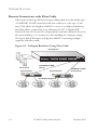
Remote Connections with Fiber Cable
Fiber optic technology allows for longer cabling than any other media type.
A 1000BASE-LX SFP transceiver link can connect to a site up to 5 km
away. This allows the EdgeIron 4802CF to serve as a collapsed backbone,
providing direct connectivity for a widespread LAN. A Gigabit SFP
transceiver can also be used for a high-speed connection between floors in
the same building, or to connect to other buildings in a campus setting.
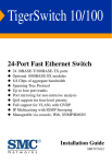
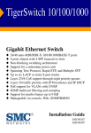
The figure below illustrates an EdgeIron 4802CF connecting multiple
segments with fiber cable.
Figure 3-3. Collapsed Backbone Using Fiber Cable
Headquarters
1000BASE-SX MMF
(500 m)
Server Farm
Remote Switch
25
26
1
2
7
8
3
4
9
10
5
6
13 14 15 16 17 18
Link
25
1000BASE-LX SMF
(5 kilometers)
Remote Switch
1
2
3
4
5
6
13
14
15
16
17
18
7
8
9
10
11
12
19
20
21
22
23
24
26
Act
Console
Link
Act
Power
Fault
Reset
Clear
Self
Test
11 12
19 20
25
21 22 23 24
26
1
2
7
8
3
4
9
10
5
6
13 14 15 16 17 18
Link
25
1
2
3
4
5
6
13
14
15
16
17
18
7
8
9
10
11
12
19
20
21
22
23
24
26
Act
Fan
Status
Console
Link
Act
Power
Fault
Reset
Clear
Self
Test
11 12
19 20
21 22 23 24
Fan
Status
10/100 Mbps Segments
...
...
3-4
© 2003 Foundry Networks, Inc.
February 2003
APPLICATION EXAMPLES
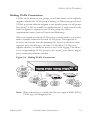
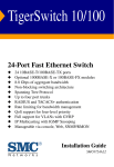
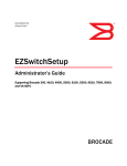
Making VLAN Connections
VLANs can be based on port groups, or each data frame can be explicitly
tagged to identify the VLAN group it belongs to. When using port-based
VLANs, ports can either be assigned to one specific group or to all groups.
Port-based VLANs are suitable for small networks. A single switch can be
easily configured to support several VLAN groups for various
organizational entities (such as Finance and Marketing).
When you expand port-based VLANs across several switches, you need to
make a separate connection for each VLAN group. This approach is,
however, inconsistent with the Spanning Tree Protocol, which can easily
segregate ports that belong to the same VLAN. When VLANs cross
separate switches, it is therefore better to use VLAN tagging. This allows
you to assign multiple VLAN groups to the “trunk” ports (that is, tagged
ports) connecting different switches.
Figure 3-4. Making VLAN Connections
R&D
VLAN 1
Tagged
Ports
Tagged Port
Untagged Ports
Finance
VLAN 2
Testing
VLAN
aware
switch
VLAN
unaware
switch
R&D
Marketing
Finance
Testing
VLAN 3
VLAN 1
VLAN 2
VLAN 4
VLAN 3
Note: When connecting to a switch that does not support IEEE 802.1Q
VLAN tags, use untagged ports.
February 2003
© 2003 Foundry Networks, Inc.
3-5
NETWORK PLANNING
Connectivity Rules
When adding hubs (repeaters) to your network, please follow the standard
connectivity rules for Ethernet, Fast Ethernet, and Gigabit Ethernet.
However, note that because switches break up the path for connected
devices into separate collision domains, you should not include the switch
or connected cabling in your calculations for cascade length involving
other devices.
1000 Mbps Gigabit Ethernet Collision Domain
Maximum 1000BASE-T Gigabit Ethernet Cable Length
Cable Type
Maximum Cable Length
Category 5, 5e, or 6 100-ohm UTP or STP 100 m (328 ft)
Maximum 1000BASE-SX Fiber Optic Cable Distance
Fiber Diameter
Fiber Bandwidth
Cable Length Range
62.5/125 micron
multimode fiber (MMF)
160 MHz/km
2-220 m (7-722 ft.)
200 MHz/km
2-275 m (7-902 ft.)
50/125 micron MMF
400 MHz/km
2-500 m (7-1641 ft.)
500 MHz/km
2-550 m (7-1805 ft.)
Maximum 1000BASE-LX Fiber Optic Cable Distance
Fiber Diameter
Fiber Bandwidth
9/125 micron single-mode N/A
fiber (SMF)
3-6
Cable Length Range
2 m - 5 km (7-16,404 ft)
© 2003 Foundry Networks, Inc.
February 2003
CONNECTIVITY RULES
100 Mbps Fast Ethernet Collision Domain
Maximum Fast Ethernet Cable Distance
Type
Cable Type
Max. Cable Length
100BASE-TX Category 5 100-ohm UTP or STP
100 m (328 ft.)
100BASE-FX 50/125 or 62.5/125 micron core
Multimode
multimode fiber (MMF)
2 km (1.24 miles)
10 Mbps Ethernet Collision Domain
Maximum Ethernet Cable Distance
Cable Type
Maximum Length
Twisted Pair, Categories 3, 4, 5
100 m (328 ft)
February 2003
© 2003 Foundry Networks, Inc.
3-7
NETWORK PLANNING
Application Notes
1. Full-duplex operation only applies to point-to-point access (such as
when a switch is attached to a workstation, server or another switch).
When the switch is connected to a hub, both devices must operate in
half-duplex mode.
2. Avoid using flow control on a port connected to a hub unless it is
actually required to solve a problem. Otherwise back pressure jamming
signals may degrade overall performance for the segment attached to
the hub.
3. For network applications that require routing between dissimilar
network types, you can attach the EdgeIron 4802CF units directly to a
router.
4. As a general rule the length of fiber optic cable for a single switched
link should not exceed:
•
Gigabit Ethernet — 550 m (1805 ft) for multimode fiber or 5 km
(16404 ft) for single-mode fiber.
However, power budget constraints must also be considered when
calculating the maximum cable length for your specific environment.
3-8
© 2003 Foundry Networks, Inc.
February 2003
CHAPTER 4
INSTALLING THE SWITCH
Selecting a Site
EdgeIron 4802CF units can be mounted in a standard 19-inch equipment
rack or on a flat surface. Be sure to follow the guidelines below when
choosing a location.
◆
The site should:
•
be at the center of all the devices you want to link and near a
power outlet.
•
be able to maintain its temperature within 0 to 50 °C (32 to
122 °F) and its humidity within 5% to 95%, non-condensing
•
provide adequate space (approximately two inches) on all sides for
proper air flow
•
be accessible for installing, cabling and maintaining the devices
•
allow the status LEDs to be clearly visible
◆
Make sure twisted-pair cable is always routed away from power lines,
fluorescent lighting fixtures and other sources of electrical
interference, such as radios and transmitters.
◆
Make sure that a separate grounded power outlet that provides 100 to
240 VAC, 50 to 60 Hz, is within 2.44 m (8 feet) of each device and is
powered from an independent circuit breaker. As with any equipment,
using a filter or surge suppressor is recommended.
February 2003
© 2003 Foundry Networks, Inc.
4-1
INSTALLING THE SWITCH
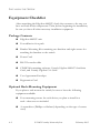
Equipment Checklist
After unpacking the EdgeIron 4802CF, check the contents to be sure you
have received all the components. Then, before beginning the installation,
be sure you have all other necessary installation equipment.
Package Contents
◆
EdgeIron 4802CF unit
◆
Four adhesive foot pads
◆
Bracket Mounting Kit containing two brackets and eight screws for
attaching the brackets to the switch
◆
Power Cord
◆
RS-232 console cable
◆
CD-ROM containing software, Foundry EdgeIron 4802CF Installation
Guide, and Foundry EdgeIron User Guide
◆
User Agreement Envelope
◆
Registration Card
Optional Rack-Mounting Equipment
If you plan to rack-mount the switch, be sure to have the following
equipment available:
4-2
◆
Four mounting screws for each device you plan to install in a
rack—these are not included
◆
A screwdriver (Phillips or flathead, depending on the type of screws
used)
© 2003 Foundry Networks, Inc.
February 2003
MOUNTING
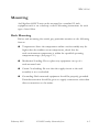
Mounting
An EdgeIron 4802CF unit can be mounted in a standard 19-inch
equipment rack or on a desktop or shelf. Mounting instructions for each
type of site follow.
Rack Mounting
Before rack mounting the switch, pay particular attention to the following
factors:
◆
Temperature: Since the temperature within a rack assembly may be
higher than the ambient room temperature, check that the
rack-environment temperature is within the specified operating
temperature range. (See page C-2.)
◆
Mechanical Loading: Do not place any equipment on top of a
rack-mounted unit.
◆
Circuit Overloading: Be sure that the supply circuit to the rack
assembly is not overloaded.
◆
Grounding: Rack-mounted equipment should be properly grounded.
Particular attention should be given to supply connections other than
direct connections to the mains.
February 2003
© 2003 Foundry Networks, Inc.
4-3
INSTALLING THE SWITCH
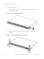
To rack-mount devices:
1. Attach the brackets to the device using the screws provided in the
Bracket Mounting Kit.
Figure 4-1. Attaching the Brackets
2. Mount the device in the rack, using four rack-mounting screws (not
provided).
Figure 4-2. Installing the Switch in a Rack
4-4
© 2003 Foundry Networks, Inc.
February 2003
MOUNTING
3. If installing a single switch only, turn to “Connecting to a Power
Source” at the end of this chapter.
4. If installing multiple switches, mount them in the rack, one below the
other, in any order.
5. If also installing RPUs, mount them in the rack below the other
devices.
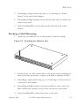
Desktop or Shelf Mounting
1. Attach the four adhesive feet to the bottom of the first switch.
Figure 4-3. Attaching the Adhesive Feet
2. Set the device on a flat surface near an AC power source, making sure
there are at least two inches of space on all sides for proper air flow.
3. If installing a single switch only, go to “Connecting to a Power Source”
at the end of this chapter.
4. If installing multiple switches, attach four adhesive feet to each one.
Place each device squarely on top of the one below, in any order.
5. If also installing RPUs, place them close to the stack.
February 2003
© 2003 Foundry Networks, Inc.
4-5
INSTALLING THE SWITCH
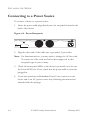
Connecting to a Power Source
To connect a device to a power source:
1. Insert the power cable plug directly into the receptacle located at the
back of the device.
Figure 4-4. Power Receptacle
2. Plug the other end of the cable into a grounded, 3-pin socket.
Note: For International use, you may need to change the AC line cord.
You must use a line cord set that has been approved for the
receptacle type in your country.
3. Check the front-panel LEDs as the device is powered on to be sure
the Power LED is lit. If not, check that the power cable is correctly
plugged in.
4. If you have purchased a Redundant Power Unit, connect it to the
device and to an AC power source now, following the instructions
included with the package.
4-6
© 2003 Foundry Networks, Inc.
February 2003
CHAPTER 5
MAKING NETWORK
CONNECTIONS
Connecting Network Devices
The EdgeIron 4802CF is designed to interconnect multiple segments (or
collision domains). It may be connected to network cards in PCs and
servers, or to hubs, switches or routers.
Note: Before connecting cables, you may want to first configure the
Spanning Tree Protocol to avoid network loops. Refer to the User
Guide for more information.
Twisted-Pair Devices
Each device requires an unshielded twisted-pair (UTP) cable with RJ-45
connectors at both ends. For 100BASE-TX connections, Category 5 cable
is required; for 10BASE-T, Category 3, 4 or 5 cable can be used.
For 1000BASE-T connections, Category 5, 5e, or 6 (recommended) cable
is required with all four wire pairs connected. You should also test the
cable installation for IEEE 802.3ab compliance. See “1000BASE-T Cable
Requirements” on page B-5.
Cabling Guidelines
The RJ-45 ports on the switch support automatic MDI/MDI-X operation,
so you can use standard straight-through twisted-pair cables to connect to
any other network device (PCs, servers, switches, routers, or hubs).
February 2003
© 2003 Foundry Networks, Inc.
5-1
MAKING NETWORK CONNECTIONS
Note: If auto-negotiation is disabled for an RJ-45 port, the auto-MDI/
MDI-X pin signal configuration is also disabled.
See Appendix B for further information on cabling.
Caution: Do not plug a phone jack connector into an RJ-45 port. This
will damage the switch. Use only twisted-pair cables with RJ-45
connectors that conform to FCC standards.
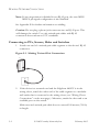
Connecting to PCs, Servers, Hubs and Switches
1. Attach one end of a twisted-pair cable segment to the device’s RJ-45
connector.
Figure 5-1. Making Twisted-Pair Connections
2. If the device is a network card and the EdgeIron 4802CF is in the
wiring closet, attach the other end of the cable segment to a modular
wall outlet that is connected to the wiring closet (see “Wiring Closet
Connections” on the next page). Otherwise, attach the other end to an
available port on the switch.
Make sure each twisted pair cable does not exceed 100 meters (328 ft)
in length.
5-2
© 2003 Foundry Networks, Inc.
February 2003
TWISTED-PAIR DEVICES
Notes: 1. When connected to a shared collision domain (such as a hub
with multiple workstations), switch ports must be set to
half-duplex mode.
2. Avoid using flow control on a port connected to a hub unless
it is actually required to solve a problem. Otherwise back
pressure jamming signals may degrade overall performance
for the segment attached to the hub.
3. As each connection is made, the green Link LED (on the EdgeIron
4802CF) corresponding to each port will light to indicate that the
connection is valid.
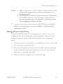
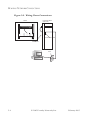
Wiring Closet Connections
Today, the punch-down block is an integral part of many of the newer
equipment racks. It is actually part of the patch panel. Instructions for
making connections in the wiring closet with this type of equipment
follow.
1. Attach one end of a patch cable to an available port on the switch, and
the other end to the patch panel.
2. If not already in place, attach one end of a cable segment to the back
of the patch panel where the punch-down block is located, and the
other end to a modular wall outlet.
3. Label the cables to simplify future troubleshooting.
February 2003
© 2003 Foundry Networks, Inc.
5-3
MAKING NETWORK CONNECTIONS
Figure 5-2. Wiring Closet Connections
Equipment Rack
(side view)
Switch
Punch-Down Block
Patch Panel
Wall
5-4
© 2003 Foundry Networks, Inc.
February 2003
APPENDIX A
TROUBLESHOOTING
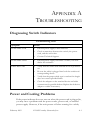
Diagnosing Switch Indicators
Troubleshooting Chart
Symptom
Action
Power LED is Off
•
Internal power supply is disconnected.
•
Check connections between the switch, the power
cord, and the wall outlet.
•
Contact Technical Support.
Power LED is Red
•
Internal power supply has failed. Contact your local
dealer for assistance.
Link LED is Off
•
Verify that the switch and attached device is powered
on.
•
Be sure the cable is plugged into both the switch and
corresponding device.
•
Verify that the proper cable type is used and its length
does not exceed specified limits.
•
Check the adapter on the attached device and cable
connections for possible defects. Replace the defective
adapter or cable if necessary.
Power and Cooling Problems
If the power indicator does not turn on when the power cord is plugged in,
you may have a problem with the power outlet, power cord, or internal
power supply. However, if the unit powers off after running for a while,
February 2003
© 2003 Foundry Networks, Inc.
A-1
TROUBLESHOOTING
check for loose power connections, power losses or surges at the power
outlet, and verify that the fans on the unit are unobstructed and running
prior to shutdown. If you still cannot isolate the problem, then the internal
power supply may be defective. In this case, contact Technical Support for
assistance.
Installation
Verify that all system components have been properly installed. If one or
more components appear to be malfunctioning (such as the power cord or
network cabling), test them in an alternate environment where you are sure
that all the other components are functioning properly.
In-Band Access
You can access the management agent in the switch from anywhere within
the attached network using Telnet, a Web browser, or other network
management software. However, you must first configure the switch with a
valid IP address, subnet mask, and default gateway. If you have trouble
establishing a link to the management agent, check to see if you have a
valid network connection. Then verify that you entered the correct IP
address. Also, be sure the port through which you are connecting to the
switch has not been disabled. If it has not been disabled, then check the
network cabling that runs between your remote location and the switch.
Note: The management agent can accept up to four simultaneous Telnet
sessions. If the maximum number of sessions already exists, an
additional Telnet connection will not be able to log into the
system.
A-2
© 2003 Foundry Networks, Inc.
February 2003
APPENDIX B
CABLES
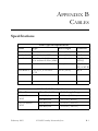
Specifications
Cable Types and Specifications
Cable
Type
Max. Length
Connector
10BASE-T
Cat. 3, 4, 5 100-ohm UTP
100 m (328 ft)
RJ-45
100BASE-TX Cat. 5 100-ohm UTP
100 m (328 ft)
RJ-45
1000BASE-SX 50/125 or 62.5/125 micron See table below
core multimode fiber (MMF)
SC, ST, LC,
MT-RJ
1000BASE-FX 9/125 9 micron SMF
5 km (3.12 miles)
SC, ST, LC,
SG, or MT-RJ
100 m (328 ft)
RJ-45
1000BASE-T
Cat. 50, 5e, 6 100-ohm
UTP
1000BASE-SX Fiber Specifications
Fiber Diameter
Fiber Bandwidth
Cable Length Range
62.5/125 micron
MMF
160 MHz/km
2-220 m (7-722 ft.)
200 MHz/km
2-275 m (7-902 ft.)
50/125 micron
MMF
400 MHz/km
2-500 m (7-1641 ft.)
500 MHz/km
2-550 m (7-1805 ft.)
February 2003
© 2003 Foundry Networks, Inc.
B-1
CABLES
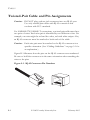
Twisted-Pair Cable and Pin Assignments
Caution: DO NOT plug a phone jack connector into any RJ-45 port.
Use only twisted-pair cables with RJ-45 connectors that
conform with FCC standards.
For 100BASE-TX/10BASE-T connections, a twisted-pair cable must have
two pairs of wires. Each wire pair is identified by two different colors. For
example, one wire might be red and the other, red with white stripes. Also,
an RJ-45 connector must be attached to both ends of the cable.
Caution: Each wire pair must be attached to the RJ-45 connectors in a
specific orientation. (See “Cabling Guidelines” on page 5-1 for
an explanation.)
Figure B-1 illustrates how the pins on the RJ-45 connector are numbered.
Be sure to hold the connectors in the same orientation when attaching the
wires to the pins.
Figure 2-1. RJ-45 Connector Pin Numbers
8
1
B-2
8
© 2003 Foundry Networks, Inc.
1
February 2003
TWISTED-PAIR CABLE AND PIN ASSIGNMENTS
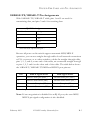
100BASE-TX/10BASE-T Pin Assignments
With 100BASE-TX/10BASE-T cable, pins 1 and 2 are used for
transmitting data, and pins 3 and 6 for receiving data.
RJ-45 Pin Assignments
Pin Number
Assignment1
1
Tx+
2
Tx-
3
Rx+
6
Rx-
1: The “+” and “-” signs represent the polarity of the
wires that make up each wire pair.
Because all ports on this switch support automatic MDI/MDI-X
operation, you can use straight-through cables for all network connections
to PCs or servers, or to other switches or hubs. In straight-through cable,
pins 1, 2, 3, and 6, at one end of the cable, are connected straight through
to pins 1, 2, 3 and 6 at the other end of the cable. The table below shows
the 10BASE-T/100BASE-TX MDI and MDI-X port pinouts.
Pin
MDI-X Signal Name
MDI Signal Name
1
Receive Data plus (RD+)
Transmit Data plus (TD+)
2
Receive Data minus (RD-)
Transmit Data minus (TD-)
3
Transmit Data plus (TD+)
Receive Data plus (RD+)
6
Transmit Data minus (TD-)
Receive Data minus (RD-)
No other pins are used.
Note: If auto-negotiation is disabled for an RJ-45 port, the auto-MDI/
MDI-X pin signal configuration is also disabled.
February 2003
© 2003 Foundry Networks, Inc.
B-3
CABLES
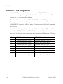
1000BASE-T Pin Assignments
1000BASE-T ports switch support automatic MDI/MDI-X operation, so
you can use straight-through cables for all network connections to PCs or
servers, or to other switches or hubs.
The table below shows the 1000BASE-T MDI and MDI-X port pinouts.
These ports require that all four pairs of wires be connected. Note that for
1000BASE-T operation, all four pairs of wires are used for both transmit
and receive.
Use 100-ohm Category 5, 5e, or 6 unshielded twisted-pair (UTP) or shielded
twisted-pair (STP) cable for 1000BASE-T connections. Also be sure that the
length of any twisted-pair connection does not exceed 100 meters (328 feet).
B-4
Pin
MDI Signal Name
MDI-X Signal Name
1
Transmit Data plus (TD1+)
Transmit Data plus (TD2 +)
2
Receive Data minus (RD1-)
Receive Data minus (RD2-)
3
Transmit Data plus (TD2+)
Transmit Data plus (TD1+)
4
Transmit Data plus (TD3+)
Transmit Data plus (TD4+)
5
Receive Data minus (RD3-)
Receive Data minus (RD4-)
6
Receive Data minus (RD2-)
Receive Data minus (RD1-)
7
Transmit Data plus (TD4+)
Transmit Data plus (TD3+)
8
Receive Data minus (RD4-)
Receive Data minus (RD3-)
© 2003 Foundry Networks, Inc.
February 2003
TWISTED-PAIR CABLE AND PIN ASSIGNMENTS
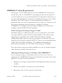
1000BASE-T Cable Requirements
All Category 5 UTP cables that are used for 100BASE-TX connections
should also work for 1000BASE-T, providing that all four wire pairs are
connected. However, it is recommended that for all critical connections, or
any new cable installations, Category 5e (enhanced Category 5) or 6 cable
should be used. The Category 5e and 6 specifications include test
parameters that are only recommendations for Category 5. Therefore, the
first step in preparing existing Category 5 cabling for running
1000BASE-T is a simple test of the cable installation to be sure that it
complies with the IEEE 802.3ab standards.
Cable Testing for Existing Category 5 Cable
Installed Category 5 cabling must pass tests for Attenuation, Near-End
Crosstalk (NEXT), and Far-End Crosstalk (FEXT). This cable testing
information is specified in the ANSI/TIA/EIA-TSB-67 standard.
Additionally, cables must also pass test parameters for Return Loss and
Equal-Level Far-End Crosstalk (ELFEXT). These tests are specified in the
ANSI/TIA/EIA-TSB-95 Bulletin, “The Additional Transmission
Performance Guidelines for 100 Ohm 4-Pair Category 5 Cabling.”
Note that when testing your cable installation, be sure to include all patch
cables between switches and end devices.
Adjusting Existing Category 5 Cabling to Run 1000BASE-T
If your existing Category 5 installation does not meet one of the test
parameters for 1000BASE-T, there are basically three measures that can be
applied to try and correct the problem:
1. Replace any Category 5 patch cables with high-performance Category
6 cables.
2. Reduce the number of connectors used in the link.
3. Reconnect some of the connectors in the link.
February 2003
© 2003 Foundry Networks, Inc.
B-5
CABLES
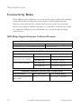
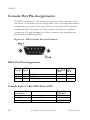
Console Port Pin Assignments
The DB-9 serial port on the switch’s rear panel is used to connect to the
switch for out-of-band console configuration. The on-board menu-driven
configuration program can be accessed from a terminal, a PC running a
terminal emulation program, or from a remote location via a modem
connection. The pin assignments used to connect to the serial port are
provided in the following tables.
Figure 2-2. DB-9 Console Port Pin Numbers
DB-9 Port Pin Assignments
EIA
CCITT Description
Circuit Signal
BB
104
RxD (Received Data)
BA
103
TxD (Transmitted Data)
AB
102
SGND (Signal Ground)
No other pins are used.
Switch’s
DB9 DTE
Pin #
2
3
5
PC DB9
DTE
Pin #
2
3
5
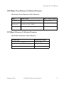
Console Port to 9-Pin DTE Port on PC
Switch’s 9-Pin
Null Modem
Serial Port
2 RXD
<---------RXD -----------3 TXD
-----------TXD ---------->
5 SGND
-----------SGND ---------No other pins are used.
B-6
© 2003 Foundry Networks, Inc.
PC’s 9-Pin
DTE Port
3 TxD
2 RxD
5 SGND
February 2003
CONSOLE PORT PIN ASSIGNMENTS
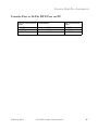
Console Port to 25-Pin DTE Port on PC
Switch’s 9-Pin Serial Null Modem
Port
2 RXD
<---------RXD -----------3 TXD
-----------TXD ---------->
5 SGND
-----------SGND ---------No other pins are used.
February 2003
© 2003 Foundry Networks, Inc.
PC’s 25-Pin DTE
Port
2 TXD
3 RXD
7 SGND
B-7
CABLES
B-8
© 2003 Foundry Networks, Inc.
February 2003
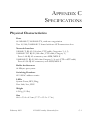
APPENDIX C
SPECIFICATIONS
Physical Characteristics
Ports
48 10BASE-T/100BASE-TX, with auto-negotiation
Two 10/100/1000BASE-T shared with two SFP transceiver slots
Network Interface
10BASE-T: RJ-45 (100-ohm, UTP cable; Categories 3, 4, 5)
100BASE-TX: RJ-45 (100-ohm, UTP cable; Category 5)
Ports 1-48: RJ-45 connector, auto MDI/MDI-X
1000BASE-T: RJ-45 (100-ohm Category 5, 5e or 6 UTP or STP cable)
Ports 49-50: RJ-45 connector, auto MDI/MDI-X
Buffer Architecture
64 Mbytes per system
Switching Database
8191 MAC address entries
LEDs
System: Power, RPU, Diag.,
Port: Link/Act., FDX
Weight
4.36 kg (9.5 lbs)
Size
44.0 x 35.4 x 4.3 cm (17.37 x 13.9 x 1.7 in.)
February 2003
© 2003 Foundry Networks, Inc.
C-1
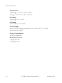
SPECIFICATIONS
Temperature
Operating: 0 to 50 °C (32 to 122 °F)
Storage: -40 to 70 °C (-40 to 158 °F)
Humidity
Operating: 10% to 90%
AC Input
100 to 240 V, 50 to 60 Hz
Power Supply
Internal, auto-ranging transformer: 90 to 260 VAC, 47 to 63 Hz
Redundant DC input
Power Consumption
48 Watts maximum
Maximum Current
5 A @ 110 VAC
2 A @ 240 VAC
C-2
© 2003 Foundry Networks, Inc.
February 2003
SWITCH FEATURES
Switch Features
Spanning Tree Protocol
Forwarding Mode
Store-and-forward
Flow Control
Full Duplex: IEEE 802.3x
Half Duplex: Back pressure
Broadcast Storm Suppression
Traffic throttled above a critical threshold
VLAN Support
Up to 255 groups; port-based or with 802.1Q VLAN tagging,
GVRP for automatic VLAN learning
Multicast Switching
IGMP Snooping
Quality of Service
Supports four levels of priority and Weighted Round Robin queueing
February 2003
© 2003 Foundry Networks, Inc.
C-3
SPECIFICATIONS
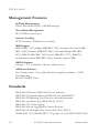
Management Features
In-Band Management
Telnet, Web-based HTTP, or SNMP manager
Out-of-Band Management
RS-232 DB-9 console port
Software Loading
TFTP in-band or XModem out-of-band
MIB Support
MIB II (RFC 1213), Bridge MIB (RFC 1493), Interfaces Evolution MIB
(RFC 2863), Ethernet MIB (RFC 2665), Extended Bridge MIB (RFC
2674), RMON MIB (RFC 2819), Entity MIB (RFC 2737), RADIUS
authentication client MIB (RFC 2618), Foundry’s private MIB
RMON Support
Groups 1, 2, 3, 9 (Statistics, History, Alarm, Event)
Additional Features
Port Trunks (static - Cisco EtherChannel compliant, dynamic - LACP)
Port Mirroring
BOOTP/DHCP Client
Standards
IEEE 802.3 Ethernet, IEEE 802.3u Fast Ethernet,
IEEE 802.3z Gigabit Ethernet, IEEE 802.3ab 1000BASE-T,
IEEE 802.1D Spanning Tree Protocol and traffic priorities,
IEEE 802.1p priority tags, IEEE 802.1Q VLAN,
IEEE 802.3ac VLAN tagging,
IEEE 802.ad Link Aggregation Control Protocol
IEEE 802.3x full-duplex flow control (ISO/IEC 8802-3)
SNMP (RFC 1157), RMON (RFC 1757 groups 1,2,3,9), RADIUS (RFC 2618)
C-4
© 2003 Foundry Networks, Inc.
February 2003
COMPLIANCES
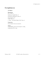
Compliances
CE Mark
Emissions
FCC Class A
Industry Canada Class A
EN55022 (CISPR 22) Class A
EN 61000-3-2/3
VCCI Class A
C-Tick - AS/NZS 3548 (1995) Class A
Immunity
EN 61000-4-2/3/4/5/6/8/11
Safety
CSA/NRTL (CSA 22.2.950 & UL 1950)
EN60950 (TÜV/GS)
February 2003
© 2003 Foundry Networks, Inc.
C-5
SPECIFICATIONS
C-6
© 2003 Foundry Networks, Inc.
February 2003
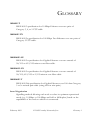
GLOSSARY
10BASE-T
IEEE 802.3 specification for 10 Mbps Ethernet over two pairs of
Category 3, 4, or 5 UTP cable.
100BASE-TX
IEEE 802.3u specification for 100 Mbps Fast Ethernet over two pairs of
Category 5 UTP cable.
1000BASE-SX
IEEE 802.3z specification for Gigabit Ethernet over two strands of
50/125 or 62.5/125 micron core fiber cable.
1000BASE-LX
IEEE 802.3z specification for Gigabit Ethernet over two strands of
50/125, 62.5/125 or 9/125 micron core fiber cable.
1000BASE-T
IEEE 802.3ab specification for Gigabit Ethernet over 100-ohm Category
5 or 5e twisted-pair cable (using all four wire pairs).
Auto-Negotiation
Signalling method allowing each node to select its optimum operational
mode (e.g., 10 Mbps or 100 Mbps and half or full duplex) based on the
capabilities of the node to which it is connected.
February 2003
© 2003 Foundry Networks, Inc.
Glossary-1
GLOSSARY
Bandwidth
The difference between the highest and lowest frequencies available for
network signals. Also synonymous with wire speed, the actual speed of the
data transmission along the cable.
Collision
A condition in which packets transmitted over the cable interfere with each
other. Their interference makes both signals unintelligible.
Collision Domain
Single CSMA/CD LAN segment.
CSMA/CD
CSMA/CD (Carrier Sense Multiple Access/Collision Detect) is the
communication method employed by Ethernet, Fast Ethernet, or Gigabit
Ethernet.
End Station
A workstation, server, or other device that does not forward traffic.
Ethernet
A network communication system developed and standardized by DEC,
Intel, and Xerox, using baseband transmission, CSMA/CD access, logical
bus topology, and coaxial cable. The successor IEEE 802.3 standard
provides for integration into the OSI model and extends the physical layer
and media with repeaters and implementations that operate on fiber, thin
coax and twisted-pair cable.
Fast Ethernet
A 100 Mbps network communication system based on Ethernet and the
CSMA/CD access method.
Glossary-2
© 2003 Foundry Networks, Inc.
February 2003
GLOSSARY
Gigabit Ethernet
A 1000 Mbps network communication system based on Ethernet and the
CSMA/CD access method.
Full Duplex
Transmission method that allows two network devices to transmit and
receive concurrently, effectively doubling the bandwidth of that link.
IEEE
Institute of Electrical and Electronic Engineers.
IEEE 802.3
Defines carrier sense multiple access with collision detection (CSMA/CD)
access method and physical layer specifications.
IEEE 802.3ab
Defines CSMA/CD access method and physical layer specifications for
1000BASE-T Fast Ethernet.
IEEE 802.3u
Defines CSMA/CD access method and physical layer specifications for
100BASE-TX Fast Ethernet.
IEEE 802.3x
Defines Ethernet frame start/stop requests and timers used for flow
control on full-duplex links.
IEEE 802.3z
Defines CSMA/CD access method and physical layer specifications for
1000BASE Gigabit Ethernet.
Local Area Network (LAN)
A group of interconnected computer and support devices.
February 2003
© 2003 Foundry Networks, Inc.
Glossary-3
GLOSSARY
LAN Segment
Separate LAN or collision domain.
LED
Light emitting diode used for monitoring a device or network condition.
Local Area Network
A group of interconnected computers and support devices.
Media Access Control (MAC)
A portion of the networking protocol that governs access to the
transmission medium, facilitating the exchange of data between network
nodes.
MIB
An acronym for Management Information Base. It is a set of database
objects that contains information about the device.
Network Diameter
Wire distance between two end stations in the same collision domain.
Redundant Power Unit (RPU)
A backup power supply that automatically takes over in case the primary
power supply should fail.
RJ-45 Connector
A connector for twisted-pair wiring.
Switched Ports
Ports that are on separate collision domains or LAN segments.
Glossary-4
© 2003 Foundry Networks, Inc.
February 2003
GLOSSARY
Transmission Control Protocol/Internet Protocol (TCP/IP)
Protocol suite that includes TCP as the primary transport protocol, and IP
as the network layer protocol.
UTP
Unshielded twisted-pair cable.
Virtual LAN (VLAN)
A Virtual LAN is a collection of network nodes that share the same
collision domain regardless of their physical location or connection point
in the network. A VLAN serves as a logical workgroup with no physical
barriers, allowing users to share information and resources as though
located on the same LAN.
February 2003
© 2003 Foundry Networks, Inc.
Glossary-5
GLOSSARY
Glossary-6
© 2003 Foundry Networks, Inc.
February 2003
INDEX
Numerics
10 Mbps connectivity rules 3-7
1000 Mbps connectivity rules 3-6
1000BASE-LX
fiber cable lengths 3-6
1000BASE-SX
fiber cable lengths 3-6
100BASE cable lengths 3-7
100BASE-FX
fiber 3-6
100BASE-TX ports 2-3
10BASE cable lengths 3-7
10BASE-T ports 2-3
A
adhesive feet, attaching 4-5
air flow requirements 4-1
applications 3-2
central wiring closet 3-3
collapsed backbone 3-2
remote connections with fiber 3-4
VLAN connections 3-5
Connectivity 3-6
connectivity rules
10 Mbps 3-7
1000 Mbps 3-6
console port 2-2
pin assignments B-6
contents of package 4-2
cooling problems A-1
cord sets, international 4-6
D
DC input 2-6
desktop mounting 4-5
device connections 5-1
E
electrical interference, avoiding 4-1
equipment checklist 4-2
Ethernet connectivity rules 3-7
F
brackets, attaching 4-4
broadcast storm control 2-2
buffers, saturation of 2-3
features C-3
management 2-8
switch 2-7
flow control, IEEE 802.3x 2-3
front panel of switch 2-1
full duplex connectivity 3-1
C
G
cable
lengths 3-7
specifications B-1
compliances
EMC C-5
safety C-5
Gigabit Ethernet cable lengths 3-6
grounding for racks 4-3
GVRP 2-2
B
February 2003
© 2003 Foundry Networks, Inc.
Index-1
INDEX
I
IEEE 802.3x flow control 2-3
IGMP 2-2
indicators, LED 2-4
installation
connecting devices to the switch 5-2
desktop or shelf mounting 4-5
port connections 5-1
power requirements 4-1
problems A-2
rack mounting 4-3
RPUs in racks 4-5
site requirements 4-1
wiring closet connections 5-3
L
LED indicators
Power 2-5
problems A-1
RPU 2-5
location requirements 4-1
M
management
agent 2-2
features 2-8, C-4
out-of-band 2-2
SNMP 2-2
Web-based 2-2
MIB support C-4
mounting the switch
in a rack 4-3
on a desktop or shelf 4-5
N
network
Index-2
connections 5-1
examples 3-2
null-modem cable 2-2
O
optional
redundant power unit 2-6
out-of-band management 2-2
P
package contents 4-2
password
support 1-2
pin assignments B-2
1000BASE-T B-4
100BASE-TX/10BASE-T B-3
25-pin DTE port B-7
console port B-6
DB-9 B-6
port saturation 2-2, 2-3
port-based VLANs 3-5
ports, connecting to 5-1
power, connecting to 4-6
problems, troubleshooting A-1
Q
QoS 2-2
R
rack mounting 4-3
rear panel of switch 2-1
rear panel receptacles 2-6
redundant power unit 2-6
RJ-45 port connections 5-1
RJ-45 ports 2-3
pinouts B-4
© 2003 Foundry Networks, Inc.
February 2003
INDEX
RMON 2-2
routing applications 3-8
RPU
connecting 4-6
installing in a rack 4-5
installing on a desktop 4-5
optional redundant power unit 2-6
RS-232 port 2-2
rubber foot pads, attaching 4-5
S
sample applications 3-2
screws for rack mounting 4-2
serial port 2-2
site selelction 4-1
SNMP agent 2-2
Spanning Tree Protocol 3-5, 5-1
specifications
compliances C-5
environmental C-2
physical C-1
power C-2
standards
compliance C-5
IEEE C-4
status LEDs 2-4
store-and-forward 2-2
Support, Technical 1-1
surge suppressor, using 4-1
switch architecture 2-2
switching
introduction to 3-1
method 2-2
e-mail 1-2
telephone 1-2
Web 1-2
Telnet A-2
temperature within a rack 4-3
troubleshooting
in-band access A-2
power and cooling problems A-1
switch indicators A-1
twisted-pair connections 5-1
V
VLANs 2-2, 3-5
tagging 3-5
W
Web-based management 2-2
T
tags
VLAN 3-5
Technical Support 1-1
February 2003
© 2003 Foundry Networks, Inc.
Index-3
INDEX
Index-4
© 2003 Foundry Networks, Inc.
February 2003