1
Foundry IronPoint 250
Installation Guide
4980 Great America Parkway
Santa Clara, CA 95054
Tel 408.207.1700
www.foundrynetworks.com
August 2007
Copyright © 2007 Foundry Networks, Inc. All rights reserved.
No part of this work may be reproduced in any form or by any means – graphic, electronic or
mechanical, including photocopying, recording, taping or storage in an information retrieval system –
without prior written permission of the copyright owner.
The trademarks, logos and service marks ("Marks") displayed herein are the property of Foundry or
other third parties. You are not permitted to use these Marks without the prior written consent of
Foundry or such appropriate third party.
Foundry Networks, BigIron, FastIron, IronView, JetCore, NetIron, ServerIron, TurboIron, IronWare, EdgeIron,
IronPoint, the Iron family of marks and the Foundry Logo are trademarks or registered trademarks of
Foundry Networks, Inc. in the United States and other countries.
All other trademarks mentioned in this document are the property of their respective owners.
Compliances
FCC - Class B
This equipment has been tested and found to comply with the limits for a Class B digital device, pursuant to Part
15 of the FCC Rules. These limits are designed to provide reasonable protection against harmful interference in
a residential installation. This equipment generates, uses and can radiate radio frequency energy and, if not
installed and used in accordance with the instructions, may cause harmful interference to radio communications. However, there is no guarantee that interference will not occur in a particular installation. If this equipment
does cause harmful interference to radio or television reception, which can be determined by turning the equipment off and on, the user is encouraged to try to correct the interference by one of the following measures:
•
•
•
•
Reorient or relocate the receiving antenna
Increase the separation between the equipment and receiver
Connect the equipment into an outlet on a circuit different from that to which the receiver is connected
Consult the dealer or an experienced radio/TV technician for help
FCC Caution: Any changes or modifications not expressly approved by the party responsible for compliance
could void the user's authority to operate this equipment. This device complies with Part 15 of the FCC Rules.
Operation is subject to the following two conditions: (1) This device may not cause harmful interference, and (2)
this device must accept any interference received, including interference that may cause undesired operation.
IMPORTANT NOTE:
FCC Radiation Exposure Statement
This equipment complies with FCC radiation exposure limits set forth for an uncontrolled environment. This
equipment should be installed and operated with a minimum distance of 20 centimeters (8 inches) between the
radiator and your body. This transmitter must not be co-located or operating in conjunction with any other
antenna or transmitter.
FCC Channel Use Statement:
The equipment version marketed in US is restricted to usage of the channels 1- 11 only.
Wireless 2.4 Ghz and 5 GHz Band Statements:
As the IronPoint can operate in the 5150-5250 MHz frequency band it is limited by the FCC, Industry Canada
and some other countries to indoor use only so as to reduce the potential for harmful interference to co-channel
Mobile Satellite systems.
High power radars are allocated as primary users (meaning they have priority) of the 5250-5350 MHz and
5650-5850 MHz bands. These radars could cause interference and/or damage to the IronPoint when used in
Canada.
The term “IC:” before the radio certification number only signifies that Industry Canada technical specifications
were met.
August 2007
© 2007 Foundry Networks, Inc.
iii
Foundry IronPoint 250 Installation Guide
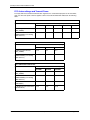
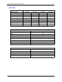
FCC Antenna Usage and Transmit Power
To comply with FCC/Canada telecommunication regulation, the conducted output power of this transmitter,
when use with each specific antenna supplied, cannot exceed the maximum limit indicated in the following
tables.
802.11a RF Power Table for FCC
External Antenna
Maximum Conducted Transmit Power (dBm)
5180 MHz
5240 MHz
5745 MHz
5785 MHz
5825 MHz
4.5 dBi Integrated Antenna
(FDS_2FED02)
11.64
14.91
24.6
24.9
25.2
8 dBi Omnidirectional Antenna
(MMO24580608) (not including
2 dBi cable loss)
10.56
13.87
23.2
23.7
23.9
802.11a Turbo Mode RF Power Table for FCC
External Antenna
Maximum Conducted Transmit Power (dBm)
5210 MHz
5760 MHz
5800 MHz
4.5 dBi Integrated Antenna
(FDS_2FED02)
12.74
24.9
24.7
8 dBi Omnidirectional Antenna
(MMO24580608) (not including
2 dBi cable loss)
11.42
23.5
23
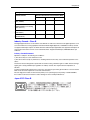
802.11b RF Power Table for FCC
External Antenna
iv
Maximum Conducted Transmit Power (dBm)
2412 MHz
2437 MHz
2462 MHz
2 dBi Integrated Antenna
(FDS_2FED02)
23.6
23.5
21.42
6 dBi Omnidirectional Antenna
(MMO24580608) (not including
1 dBi cable loss)
19.25
20.6
20.5
4 dBi Bi-Directional Antenna
(MHA2400PT)
17.25
18.75
18.5
13 dBi Directional Panel Antenna 17.25
(MP24013XFPT)
18.75
15.95
© 2007 Foundry Networks, Inc.
August 2007
Compliances
802.11g RF Power Table for FCC
External Antenna
Maximum Conducted Transmit Power (dBm)
2412 MHz
2437 MHz
2462 MHz
2 dBi Integrated Antenna
(FDS_2FED02)
21.1
24.5
17.68
6 dBi Omnidirectional Antenna
(MMO24580608) (not including
1 dBi cable loss)
19.4
24
17.2
4 dBi Bi-Directional Antenna
(MHA2400PT)
19.4
24
16.7
21.75
11.6
13 dBi Directional Panel Antenna 15.6
(MP24013XFPT)
Industry Canada - Class B
This digital apparatus does not exceed the Class B limits for radio noise emissions from digital apparatus as set
out in the interference-causing equipment standard entitled “Digital Apparatus,” ICES-003 of Industry Canada.
Cet appareil numérique respecte les limites de bruits radioélectriques applicables aux appareils numériques de
Classe B prescrites dans la norme sur le matérial brouilleur: “Appareils Numériques,” NMB-003 édictée par
l’Industrie.
Industry Canada Statement
Operation is subject to the following two conditions:
1) This device may not cause interference and
2) This device must accept any interference, including interference that may cause undesired operation of the
device
This device has been designed to operate with an antenna having a maximum gain of 13 dBi. Antenna having a
higher gain is strictly prohibited per regulations of Industry Canada. The required antenna Impedance is
50 ohms.
To reduce potential radio interference to other users, the antenna type and its gain should be so chosen that the
EIRP is not more than required for successful communication.
Because high power radars are allocated as primary users (meaning they have priority) in 5250-5350 MHz,
these radars could cause interference and/or damage to license exempt LAN devices.
Japan VCCI Class B
August 2007
© 2007 Foundry Networks, Inc.
v
Foundry IronPoint 250 Installation Guide
EC Declaration of Conformity
0560
Contact Foundry Networks at:
Foundry Networks, Inc.
4980 Great America Parkway
Santa Clara, CA 95054
Marking by the above symbol indicates compliance with the Essential Requirements of the R&TTE Directive of
the European Union (1999/5/EC). This equipment meets the following conformance standards:
•
•
•
•
EN 60950 (IEC 60950) - Product Safety
EN 301 893 - Technical requirements for 5 GHz radio equipment
EN 300 328 - Technical requirements for 2.4 GHz radio equipment
EN 301 489-1 / EN 301 489-17 - EMC requirements for radio equipment
Countries of Operation & Conditions of Use in the European Community
This device is intended to be operated in all countries of the European Community. It is intended only for indoor
use. License requirements and allowed channels of operation apply in some countries as described below:
Note: The user must use the configuration utility provided with this product to ensure the channels
of operation are in conformance with the spectrum usage rules for European Community countries
as described below.
• This device requires that the user or installer properly enter the current country of operation in the Command
Line Interface (CLI) as described in the user guide, before operating this device.
• This device will automatically limit the allowable channels determined by the current country of operation.
Incorrectly entering the country of operation may result in illegal operation and may cause harmful interference
to other system. The user is obligated to ensure the device is operating according to the channel limitations,
indoor/outdoor restrictions and license requirements for each European Community country as described in
this document.
• This device employs a radar detection feature required for European Community operation in the 5 GHz band.
This feature is automatically enabled when the country of operation is correctly configured for any European
Community country. The presence of nearby radar operation may result in temporary interruption of operation
of this device. The radar detection feature will automatically restart operation on a channel free of radar.
• The 5 GHz Turbo Mode feature is not allowed for operation in any European Community country. The current
setting for this feature is found in the 5 GHz 802.11a Radio Settings Window as described in the user guide.
• The 5 GHz radio's AutoChannelSelect/SmartSelect setting described in the user guide must always remain
enabled to ensure that automatic 5 GHz channel selection complies with European requirements. The current
setting for this feature is found in the 5 GHz 802.11a Radio Settings Window as described in the user guide.
• This device is restricted to indoor use when operated in the European Community using the 5.15 - 5.25 GHz
band: Channels 36, 40, 44, 48. See table below for allowed 5 GHz channels by country.
• This device is restricted for indoor use when operated in all countries of the European Community using the
2.4 GHz band: Channels 1 - 13.
vi
© 2007 Foundry Networks, Inc.
August 2007
Compliances
Operation Using 5 GHz Channels in the European Community
The user/installer must use the provided configuration utility to check the current channel of operation and make
necessary configuration changes to ensure operation occurs in conformance with European National spectrum
usage laws as described below and elsewhere in this document.
Allowed 5GHz Channels in Each European Community Country
Allowed Frequency Bands
Allowed Channel Numbers
Countries
5.15 - 5.25* GHz
36, 40, 44, 48
Austria, Belgium, Cyprus, Czech
Republic, Denmark, Estonia,
Finland, France, Germany, Iceland,
Ireland, Italy, Latvia, Liechtenstein,
Lithuania, Luxembourg, Malta,
Netherlands, Norway, Poland,
Portugal, Slovakia, Slovenia, Spain,
Sweden, Switzerland, U.K.
5 GHz Operation Not Allowed
None
Greece, Hungary
* Outdoor operation is not allowed using 5.15-5.25 GHz bands (Channels 36 to 48).
By selecting the appropriate country codes detailed on page 4-7 of this guide you will ensure the device operates within the frequency restrictions detailed above. You are responsible for ensuring the device is used
indoors-only and for private use only as applicable.
Transmit Power Control (TPC) for 5GHz Operation
The end-user must operate this device in accordance with European regulatory requirements for Transmit
Power Control. This device employs Transmit Power Control (TPC) to reduce the potential for interference to
other communication systems operating in the 5 GHz frequency bands. The TPC feature implemented in this
wireless LAN device must be configured by the end-user when operating in any European Community country.
The required configuration procedure for TPC is found in the user guide for this product.
Note: The TPC procedure should be repeated when relocating this wireless device within the
current wireless network or to a wireless network in a new location.
Declaration of Conformity in Languages of the European Community
English
Hereby, Foundry Networks, declares that this Radio LAN device is in compliance with the
essential requirements and other relevant provisions of Directive 1999/5/EC.
Finnish
Valmistaja Foundry Networks vakuuttaa täten että Radio LAN device tyyppinen laite on
direktiivin 1999/5/EY oleellisten vaatimusten ja sitä koskevien direktiivin muiden ehtojen
mukainen.
Dutch
Hierbij verklaart Foundry Networks dat het toestel Radio LAN device in overeenstemming
is met de essentiële eisen en de andere relevante bepalingen van richtlijn 1999/5/EG
Bij deze Foundry Networks dat deze Radio LAN device voldoet aan de essentiële eisen en
aan de overige relevante bepalingen van Richtlijn 1999/5/EC.
French
Par la présente Foundry Networks déclare que l'appareil Radio LAN device est conforme
aux exigences essentielles et aux autres dispositions pertinentes de la directive 1999/5/CE
Swedish
Härmed intygar Foundry Networks att denna Radio LAN device står I överensstämmelse
med de väsentliga egenskapskrav och övriga relevanta bestämmelser som framgår av
direktiv 1999/5/EG.
Danish
Undertegnede Foundry Networks erklærer herved, at følgende udstyr Radio LAN device
overholder de væsentlige krav og øvrige relevante krav i direktiv 1999/5/EF
August 2007
© 2007 Foundry Networks, Inc.
vii
Foundry IronPoint 250 Installation Guide
German
Hiermit erklärt Foundry Networks, dass sich dieser/diese/dieses Radio LAN device in
Übereinstimmung mit den grundlegenden Anforderungen und den anderen relevanten
Vorschriften der Richtlinie 1999/5/EG befindet". (BMWi)
Hiermit erklärt Foundry Networks die Übereinstimmung des Gerätes Radio LAN device mit
den grundlegenden Anforderungen und den anderen relevanten Festlegungen der
Richtlinie 1999/5/EG. (Wien)
Greek
Με την παρουσα Foundry Networks δηλωνει οτι radio LAN device συµµορφωνεται προσ
τισ ουσιωδεισ απαιτησεισ και τισ λοιπεσ σΧετικεσ διαταξεισ τησ οδηγιασ 1999/5/εκ
Italian
Con la presente Foundry Networks dichiara che questo Radio LAN device è conforme ai
requisiti essenziali ed alle altre disposizioni pertinenti stabilite dalla direttiva 1999/5/CE.
Spanish
Por medio de la presente Foundry Networks declara que el Radio LAN device cumple con
los requisitos esenciales y cualesquiera otras disposiciones aplicables o exigibles de la
Directiva 1999/5/CE
Portuguese
Foundry Networks declara que este Radio LAN device está conforme com os requisitos
essenciais e outras disposições da Directiva 1999/5/CE.
Australia/New Zealand AS/NZS 4771
ARBN 094 044 809
Contact Foundry Networks at:
Foundry Networks, Inc.
4980 Great America Parkway
Santa Clara, CA 95054
Safety Compliance
Power Cord Safety
Please read the following safety information carefully before installing the access point:
WARNING:
Installation and removal of the unit must be carried out by qualified personnel only.
• The unit must be connected to an earthed (grounded) outlet to comply with international safety standards.
• Do not connect the unit to an A.C. outlet (power supply) without an earth (ground) connection.
• The appliance coupler (the connector to the unit and not the wall plug) must have a configuration for mating
with an EN 60320/IEC 320 appliance inlet.
• The socket outlet must be near to the unit and easily accessible. You can only remove power from the unit by
disconnecting the power cord from the outlet.
• This unit operates under SELV (Safety Extra Low Voltage) conditions according to
IEC 60950. The conditions are only maintained if the equipment to which it is connected also operates under
SELV conditions.
France and Peru only
This unit cannot be powered from IT† supplies. If your supplies are of IT type, this unit must be powered by 230
V (2P+T) via an isolation transformer ratio 1:1, with the secondary connection point labelled Neutral, connected
directly to earth (ground).
†
viii
Impédance à la terre
© 2007 Foundry Networks, Inc.
August 2007
Compliances
Power Cord Set
U.S.A. and Canada
The cord set must be UL-approved and CSA certified.
The minimum specifications for the flexible cord are:
- No. 18 AWG - not longer than 2 meters, or 16 AWG.
- Type SV or SJ
- 3-conductor
The cord set must have a rated current capacity of at least 10 A
The attachment plug must be an earth-grounding type with NEMA 5-15P (15 A, 125
V) or NEMA 6-15P (15 A, 250 V) configuration.
Denmark
The supply plug must comply with Section 107-2-01, Standard DK2-1a or DK2-5a.
Switzerland
The supply plug must comply with SEV/ASE 1011.
U.K.
The supply plug must comply with BS1363 (3-pin 13 A) and be fitted with a 5 A fuse
which complies with BS1362.
The mains cord must be <HAR> or <BASEC> marked and be of type
HO3VVF3GO.75 (minimum).
Europe
The supply plug must comply with CEE7/7 (“SCHUKO”).
The mains cord must be <HAR> or <BASEC> marked and be of type
HO3VVF3GO.75 (minimum).
IEC-320 receptacle.
Veuillez lire à fond l'information de la sécurité suivante avant d'installer le access point:
AVERTISSEMENT:
qualifié.
L’installation et la dépose de ce groupe doivent être confiés à un personnel
• Ne branchez pas votre appareil sur une prise secteur (alimentation électrique) lorsqu'il n'y a pas de connexion
de mise à la terre (mise à la masse).
• Vous devez raccorder ce groupe à une sortie mise à la terre (mise à la masse) afin de respecter les normes
internationales de sécurité.
• Le coupleur d’appareil (le connecteur du groupe et non pas la prise murale) doit respecter une configuration
qui permet un branchement sur une entrée d’appareil EN 60320/IEC 320.
• La prise secteur doit se trouver à proximité de l’appareil et son accès doit être facile. Vous ne pouvez mettre
l’appareil hors circuit qu’en débranchant son cordon électrique au niveau de cette prise.
• L’appareil fonctionne à une tension extrêmement basse de sécurité qui est conforme à la norme IEC 60950.
Ces conditions ne sont maintenues que si l’équipement auquel il est raccordé fonctionne dans les mêmes
conditions.
France et Pérou uniquement:
Ce groupe ne peut pas être alimenté par un dispositif à impédance à la terre. Si vos alimentations sont du type
impédance à la terre, ce groupe doit être alimenté par une tension de 230 V (2 P+T) par le biais d’un transformateur d’isolement à rapport 1:1, avec un point secondaire de connexion portant l’appellation Neutre et avec
raccordement direct à la terre (masse).
August 2007
© 2007 Foundry Networks, Inc.
ix
Foundry IronPoint 250 Installation Guide
Cordon électrique - Il doit être agréé dans le pays d’utilisation
Etats-Unis et Canada:
Le cordon doit avoir reçu l’homologation des UL et un certificat de la CSA.
Les spécifications minimales pour un cable flexible sont AWG No. 18, ou AWG No. 16
pour un cable de longueur inférieure à 2 mètres.
- type SV ou SJ
- 3 conducteurs
Le cordon doit être en mesure d’acheminer un courant nominal d’au moins 10 A.
La prise femelle de branchement doit être du type à mise à la terre (mise à la masse)
et respecter la configuration NEMA 5-15P (15 A, 125 V) ou NEMA 6-15P (15 A, 250
V).
Danemark:
La prise mâle d’alimentation doit respecter la section 107-2-01 de la norme DK2 1a
ou DK2 5a.
Suisse:
La prise mâle d’alimentation doit respecter la norme SEV/ASE 1011.
Europe
La prise secteur doit être conforme aux normes CEE 7/7 (“SCHUKO”)
LE cordon secteur doit porter la mention <HAR> ou <BASEC> et doit être de type
HO3VVF3GO.75 (minimum).
Bitte unbedingt vor dem Einbauen des access point die folgenden Sicherheitsanweisungen durchlesen:
WARNUNG: Die Installation und der Ausbau des Geräts darf nur durch Fachpersonal erfolgen.
• Das Gerät sollte nicht an eine ungeerdete Wechselstromsteckdose angeschlossen werden.
• Das Gerät muß an eine geerdete Steckdose angeschlossen werden, welche die internationalen
Sicherheitsnormen erfüllt.
• Der Gerätestecker (der Anschluß an das Gerät, nicht der Wandsteckdosenstecker) muß einen gemäß EN
60320/IEC 320 konfigurierten Geräteeingang haben.
• Die Netzsteckdose muß in der Nähe des Geräts und leicht zugänglich sein. Die Stromversorgung des Geräts
kann nur durch Herausziehen des Gerätenetzkabels aus der Netzsteckdose unterbrochen werden.
• Der Betrieb dieses Geräts erfolgt unter den SELV-Bedingungen (Sicherheitskleinstspannung) gemäß IEC
60950. Diese Bedingungen sind nur gegeben, wenn auch die an das Gerät angeschlossenen Geräte unter
SELV-Bedingungen betrieben werden.
Stromkabel. Dies muss von dem Land, in dem es benutzt wird geprüft werden:
Schweiz
Dieser Stromstecker muß die SEV/ASE 1011Bestimmungen einhalten.
Europe
Das Netzkabel muß vom Typ HO3VVF3GO.75 (Mindestanforderung) sein und die
Aufschrift <HAR> oder <BASEC> tragen.
Der Netzstecker muß die Norm CEE 7/7 erfüllen (”SCHUKO”).
x
© 2007 Foundry Networks, Inc.
August 2007
Contents
Compliances . . . . . . . . . . . . . . . . . . . . . . . . . . . . . . . . . . . . . . . . . . . . . . . . . . . . . . . . . . . . . . . . . . . .iii
Chapter 1.
About This Guide . . . . . . . . . . . . . . . . . . . . . . . . . . . . . . . . . . . . . . . . . . . . . . . . . . . . . . . . . . . . . . .1-1
Audience . . . . . . . . . . . . . . . . . . . . . . . . . . . . . . . . . . . . . . . . . . . . . . . . . . . . . . . . . . . . . . . . . . .1-1
Nomenclature . . . . . . . . . . . . . . . . . . . . . . . . . . . . . . . . . . . . . . . . . . . . . . . . . . . . . . . . . . . . . . .1-1
How to Get Help . . . . . . . . . . . . . . . . . . . . . . . . . . . . . . . . . . . . . . . . . . . . . . . . . . . . . . . . . . . . .1-1
Foundry Networks Technical Support . . . . . . . . . . . . . . . . . . . . . . . . . . . . . . . . . . . . . . . . . .1-1
Web Access . . . . . . . . . . . . . . . . . . . . . . . . . . . . . . . . . . . . . . . . . . . . . . . . . . . . . . . . . . . . .1-2
E-mail Access . . . . . . . . . . . . . . . . . . . . . . . . . . . . . . . . . . . . . . . . . . . . . . . . . . . . . . . . . . . .1-2
Telephone Access . . . . . . . . . . . . . . . . . . . . . . . . . . . . . . . . . . . . . . . . . . . . . . . . . . . . . . . . .1-2
Warranty Coverage . . . . . . . . . . . . . . . . . . . . . . . . . . . . . . . . . . . . . . . . . . . . . . . . . . . . . . . . . . .1-2
Related Publications . . . . . . . . . . . . . . . . . . . . . . . . . . . . . . . . . . . . . . . . . . . . . . . . . . . . . . . . . .1-2
What’s New in this Edition . . . . . . . . . . . . . . . . . . . . . . . . . . . . . . . . . . . . . . . . . . . . . . . . . . . . . .1-2
Chapter 2.
About the IronPoint 250 . . . . . . . . . . . . . . . . . . . . . . . . . . . . . . . . . . . . . . . . . . . . . . . . . . . . . . . . . .2-1
Overview . . . . . . . . . . . . . . . . . . . . . . . . . . . . . . . . . . . . . . . . . . . . . . . . . . . . . . . . . . . . . . . . . . .2-1
Radio Characteristics . . . . . . . . . . . . . . . . . . . . . . . . . . . . . . . . . . . . . . . . . . . . . . . . . . . . . .2-2
Management Options . . . . . . . . . . . . . . . . . . . . . . . . . . . . . . . . . . . . . . . . . . . . . . . . . . . . . .2-2
Description of Hardware . . . . . . . . . . . . . . . . . . . . . . . . . . . . . . . . . . . . . . . . . . . . . . . . . . . . . . .2-3
Ethernet Port . . . . . . . . . . . . . . . . . . . . . . . . . . . . . . . . . . . . . . . . . . . . . . . . . . . . . . . . . . . . .2-3
Antennas . . . . . . . . . . . . . . . . . . . . . . . . . . . . . . . . . . . . . . . . . . . . . . . . . . . . . . . . . . . . . . . .2-3
Optional External Antenna . . . . . . . . . . . . . . . . . . . . . . . . . . . . . . . . . . . . . . . . . . . . . . . . . .2-3
Status LEDs . . . . . . . . . . . . . . . . . . . . . . . . . . . . . . . . . . . . . . . . . . . . . . . . . . . . . . . . . . . . .2-5
Security Slot . . . . . . . . . . . . . . . . . . . . . . . . . . . . . . . . . . . . . . . . . . . . . . . . . . . . . . . . . . . . .2-6
Console Port . . . . . . . . . . . . . . . . . . . . . . . . . . . . . . . . . . . . . . . . . . . . . . . . . . . . . . . . . . . . .2-6
Reset Button . . . . . . . . . . . . . . . . . . . . . . . . . . . . . . . . . . . . . . . . . . . . . . . . . . . . . . . . . . . . .2-6
Power Connector . . . . . . . . . . . . . . . . . . . . . . . . . . . . . . . . . . . . . . . . . . . . . . . . . . . . . . . . .2-6
August 2007
© 2007 Foundry Networks, Inc.
xi
Foundry IronPoint 250 Installation Guide
Features and Benefits . . . . . . . . . . . . . . . . . . . . . . . . . . . . . . . . . . . . . . . . . . . . . . . . . . . . . . . . .2-7
Connectivity . . . . . . . . . . . . . . . . . . . . . . . . . . . . . . . . . . . . . . . . . . . . . . . . . . . . . . . . . . . . . .2-7
Management . . . . . . . . . . . . . . . . . . . . . . . . . . . . . . . . . . . . . . . . . . . . . . . . . . . . . . . . . . . . .2-7
Chapter 3.
Network Planning . . . . . . . . . . . . . . . . . . . . . . . . . . . . . . . . . . . . . . . . . . . . . . . . . . . . . . . . . . . . . . .3-1
Network Topologies . . . . . . . . . . . . . . . . . . . . . . . . . . . . . . . . . . . . . . . . . . . . . . . . . . . . . . . . . . .3-1
Infrastructure Wireless LAN . . . . . . . . . . . . . . . . . . . . . . . . . . . . . . . . . . . . . . . . . . . . . . . . .3-2
Infrastructure Wireless LAN for Roaming Wireless PCs . . . . . . . . . . . . . . . . . . . . . . . . . . . .3-2
Chapter 4.
Installing the IronPoint 250 Access Point . . . . . . . . . . . . . . . . . . . . . . . . . . . . . . . . . . . . . . . . . . .4-1
Unpacking the IronPoint Access Point . . . . . . . . . . . . . . . . . . . . . . . . . . . . . . . . . . . . . . . . . . . .4-1
Installing the IronPoint Access Point . . . . . . . . . . . . . . . . . . . . . . . . . . . . . . . . . . . . . . . . . . . . . .4-1
Placing the Access Point on a Desktop or Shelf . . . . . . . . . . . . . . . . . . . . . . . . . . . . . . . . . .4-2
Attaching the Access Point to a Wall Using the Mounting Bracket . . . . . . . . . . . . . . . . . . . .4-2
Attaching the Access Point to a Suspended Ceiling . . . . . . . . . . . . . . . . . . . . . . . . . . . . . . .4-4
Locking the Access Point . . . . . . . . . . . . . . . . . . . . . . . . . . . . . . . . . . . . . . . . . . . . . . . . . . .4-5
Installing an External Antenna . . . . . . . . . . . . . . . . . . . . . . . . . . . . . . . . . . . . . . . . . . . . . . . . . . .4-5
Powering Up the Access Point . . . . . . . . . . . . . . . . . . . . . . . . . . . . . . . . . . . . . . . . . . . . . . . . . .4-6
Adding the IronPoint Access Point to the Network . . . . . . . . . . . . . . . . . . . . . . . . . . . . . . . . . . .4-7
Chapter 5.
Making a Network Connection . . . . . . . . . . . . . . . . . . . . . . . . . . . . . . . . . . . . . . . . . . . . . . . . . . . .5-1
Connecting to a Network Device . . . . . . . . . . . . . . . . . . . . . . . . . . . . . . . . . . . . . . . . . . . . . . . . .5-1
Twisted-Pair Cable . . . . . . . . . . . . . . . . . . . . . . . . . . . . . . . . . . . . . . . . . . . . . . . . . . . . . . . . . . .5-1
Cabling Guidelines . . . . . . . . . . . . . . . . . . . . . . . . . . . . . . . . . . . . . . . . . . . . . . . . . . . . . . . .5-1
Connecting to a Switch, Hub, PC, or Server . . . . . . . . . . . . . . . . . . . . . . . . . . . . . . . . . . . . .5-2
Appendix A.
Troubleshooting . . . . . . . . . . . . . . . . . . . . . . . . . . . . . . . . . . . . . . . . . . . . . . . . . . . . . . . . . . . . . . . A-1
Diagnosing Access Point Indicators . . . . . . . . . . . . . . . . . . . . . . . . . . . . . . . . . . . . . . . . . . . . . A-1
Installation . . . . . . . . . . . . . . . . . . . . . . . . . . . . . . . . . . . . . . . . . . . . . . . . . . . . . . . . . . . . . . . . . A-1
Console Access . . . . . . . . . . . . . . . . . . . . . . . . . . . . . . . . . . . . . . . . . . . . . . . . . . . . . . . . . . . . . A-1
In-Band Access . . . . . . . . . . . . . . . . . . . . . . . . . . . . . . . . . . . . . . . . . . . . . . . . . . . . . . . . . . . . . A-2
Wireless Client Network Access . . . . . . . . . . . . . . . . . . . . . . . . . . . . . . . . . . . . . . . . . . . . . . . . A-2
Lost Password . . . . . . . . . . . . . . . . . . . . . . . . . . . . . . . . . . . . . . . . . . . . . . . . . . . . . . . . . . . . . . A-3
Reset the Access Point Default Settings . . . . . . . . . . . . . . . . . . . . . . . . . . . . . . . . . . . . . . . . . . A-3
Appendix B.
Cables . . . . . . . . . . . . . . . . . . . . . . . . . . . . . . . . . . . . . . . . . . . . . . . . . . . . . . . . . . . . . . . . . . . . . . . B-1
Specifications . . . . . . . . . . . . . . . . . . . . . . . . . . . . . . . . . . . . . . . . . . . . . . . . . . . . . . . . . . . . . . B-1
Twisted-Pair Cable and Pin Assignments . . . . . . . . . . . . . . . . . . . . . . . . . . . . . . . . . . . . . . . . . B-1
100BASE-TX/10BASE-T Pin Assignments . . . . . . . . . . . . . . . . . . . . . . . . . . . . . . . . . . . . . B-2
Straight-Through Wiring . . . . . . . . . . . . . . . . . . . . . . . . . . . . . . . . . . . . . . . . . . . . . . . . . . . B-2
xii
© 2007 Foundry Networks, Inc.
August 2007
Contents
Crossover Wiring . . . . . . . . . . . . . . . . . . . . . . . . . . . . . . . . . . . . . . . . . . . . . . . . . . . . . . . . . B-2
Console Port Pin Assignments . . . . . . . . . . . . . . . . . . . . . . . . . . . . . . . . . . . . . . . . . . . . . . . . . B-3
Wiring Map for Serial Cable . . . . . . . . . . . . . . . . . . . . . . . . . . . . . . . . . . . . . . . . . . . . . . . . B-3
Appendix C.
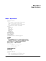
Specifications . . . . . . . . . . . . . . . . . . . . . . . . . . . . . . . . . . . . . . . . . . . . . . . . . . . . . . . . . . . . . . . . . C-1
General Specifications . . . . . . . . . . . . . . . . . . . . . . . . . . . . . . . . . . . . . . . . . . . . . . . . . . . . . . . . C-1
Sensitivity . . . . . . . . . . . . . . . . . . . . . . . . . . . . . . . . . . . . . . . . . . . . . . . . . . . . . . . . . . . . . . C-4
Maximum Distance Tables . . . . . . . . . . . . . . . . . . . . . . . . . . . . . . . . . . . . . . . . . . . . . . . . . . . . C-5
Appendix 1.
Cautions and Warnings . . . . . . . . . . . . . . . . . . . . . . . . . . . . . . . . . . . . . . . . . . . . . . . . . . . . . . . . . .1-1
Cautions . . . . . . . . . . . . . . . . . . . . . . . . . . . . . . . . . . . . . . . . . . . . . . . . . . . . . . . . . . . . . . . . . . .1-1
Warnings . . . . . . . . . . . . . . . . . . . . . . . . . . . . . . . . . . . . . . . . . . . . . . . . . . . . . . . . . . . . . . . . . . .1-3
Glossary
Index
August 2007
© 2007 Foundry Networks, Inc.
xiii
Foundry IronPoint 250 Installation Guide
xiv
© 2007 Foundry Networks, Inc.
August 2007
Chapter 1
About This Guide
The IronPoint™ 250 Access Point is a device that allows wireless clients to connect to your
enterprise network. It is a full-featured access point that can be managed as a single device.
This guide presents the procedures for installing the IronPoint™ 250 Access Point.
Audience
This guide is for system administrators with a working knowledge of wireless networks and network
management.
You should be familiar with switching and networking concepts.
Nomenclature
This guide uses the following typographical conventions to show information:
Warning:
A warning calls your attention to a possible hazard that can cause injury or death.
Caution:
A caution calls your attention to a possible hazard that can damage equipment.
Note: A note emphasizes an important fact or calls your attention to a dependency.
How to Get Help
If you need assistance, Foundry Networks is committed to ensuring that your investment in our
products remains cost-effective by offering a variety of support options.
Foundry Networks Technical Support
Foundry Networks technical support will ensure that the fast and easy access that you have come to
expect from your Foundry Networks products will be maintained.
August 2007
© 2007 Foundry Networks, Inc.
1-1
Foundry IronPoint 250 Installation Guide
Web Access
Point your browser to the kp.foundrynet.com to access the Foundry Knowledge Portal.
Note: Check with your sales account representative to determine how to obtain a valid user name
and password for the Foundry Knowledge Portal.
E-mail Access
Technical requests can also be sent to the e-mail address: [email protected]
Telephone Access
◆
1.877.TURBOCALL (887.2622): United States
◆
1.408.586.1881: Outside the United States
Warranty Coverage
Contact Foundry Networks using any of the methods listed above for information about the standard
and extended warranties.
Related Publications
Refer to the Foundry IronPoint Access Point User Guide for instructions on how to configure and
manage the access point.
What’s New in this Edition
This is the first release of this guide.
1-2
© 2007 Foundry Networks, Inc.
August 2007
Chapter 2
About the IronPoint 250
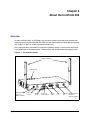
Overview
Foundry’s IronPoint 250 is an IEEE 802.11a/g enterprise wireless access point that provides highspeed data communications between the wired LAN and fixed, portable or mobile devices equipped
with an 802.11a, 802.11b, or 802.11g wireless network card.
The access point offers full network management capabilities through a command line interface for
initial configuration and troubleshooting, a Web interface, and Simple Network Management tools.
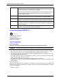
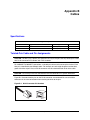
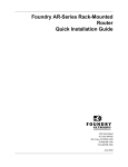
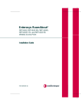
Figure 2-1. Top and Front Panels
Integrated Antennas
LED Indicators
Lock
802.11b/g
802.11a
External Antenna
Connector
(802.11a Radio)
August 2007
DC Power
Socket
DC 48V / 0.38A
Bracket
Screw
POE In
Reset
RJ-45 Port,
PoE Connector
Console
Reset
Button
© 2007 Foundry Networks, Inc.
Console
Port
Security
Slot
External Antenna
Connector
(802.11b/g Radio)
2-1
Foundry IronPoint 250 Installation Guide
Radio Characteristics
The IEEE 802.11a/g standard uses a radio modulation technique known as Orthogonal Frequency
Division Multiplexing (OFDM), and a shared collision domain (CSMA/CA). It operates at the 5 GHz
Unlicensed National Information Infrastructure (UNII) band for connections to 802.11a clients, and at
2.4 GHz for connections to 802.11g clients.
IEEE 802.11g includes backward compatibility with the IEEE 802.11b standard. IEEE 802.11b also
operates at 2.4 GHz, but uses Direct Sequence Spread Spectrum (DSSS) modulation technology to
achieve a communication rate of up to 11 Mbps.
The access point also supports a 54 Mbps half-duplex connection to Ethernet networks for each
active channel (up to 108 Mbps in turbo mode on the 802.11a interface).
Management Options
The IronPoint 250 contains LEDs for “at-a- glance” monitoring of wireless and network port status. It
also includes a built-in network management agent that allows the access point to be managed inband using SNMP, with a Web browser, or remotely via Telnet and SSH. The access point provides
an RS-232 DCE serial port (DB-9 connector) on the front panel for out-of-band management. A PC
may be connected to this port for configuration and monitoring out-of band via a null-modem serial
cable. (See “Console Port Pin Assignments” on page B-3 for wiring options.)
For a detailed description of the access point’s management features, refer to the Foundry IronPoint
Access Point User Guide.
2-2
© 2007 Foundry Networks, Inc.
August 2007
About the IronPoint 250
Description of Hardware
Ethernet Port
The access point has one 10BASE-T/100BASE-TX RJ-45 Ethernet port that can be attached directly
to a 10BASE-T/100BASE-TX/1000BASE-T wired network. The wired network must conform to the
IEEE 802.3-2005 specifications.
The Ethernet port supports automatic MDI/MDI-X operation, so you can use straight-through cables
for all network connections to PCs, switches, or hubs.
The access point appears as an Ethernet node and performs a bridging function by moving packets
from the wired network to remote workstations in the wireless infrastructure.
Note: The RJ-45 port supports Power over Ethernet (PoE) based on the IEEE 802.3af standard.
Refer to the description for the “Power Connector” for information on supplying power to the access
point’s network port from a network device, such as a switch, that provides Power over Ethernet
(PoE).
Antennas
The access point includes two integrated diversity antennas for wireless communications. A diversity
antenna system uses two identical antennas to receive and transmit signals, helping to avoid
multipath fading effects. When receiving, the access point checks both antennas and selects the one
with the strongest signal. When transmitting, it will continue to use the antenna previously selected
for receiving. The access point never transmits from both antennas at the same time.
The antennas transmit the outgoing signal as a toroidal sphere (doughnut shaped), with the
coverage extending most in a direction perpendicular to the antenna. The antenna should be
adjusted to an angle that provides appropriate coverage for the service area. For further information,
see “Installing the IronPoint Access Point” on page 4-1.
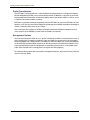
Optional External Antenna
The access point supports RP-SMA external antenna connectors for both the 2.4 GHz and 5 GHz
radios. External antennas offer a variety of options for extending the radio range and shaping the
coverage area. When an external antenna is connected, you must manually configure the software
to disable the two integrated antennas and uses only the external antenna.
August 2007
© 2007 Foundry Networks, Inc.
2-3
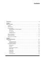
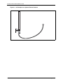
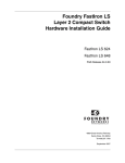
Foundry IronPoint 250 Installation Guide
Figure 2-2. An Example of an Optional External Antenna
2-4
© 2007 Foundry Networks, Inc.
August 2007
About the IronPoint 250
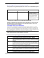
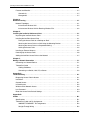
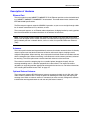
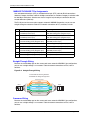
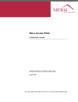
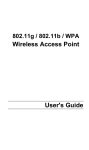
Status LEDs
The access point includes four status LED indicators, as described in the following figure and table.
Figure 2-3. Status LEDs
Ethernet
Link/Activity
Power
802.11a
Wireless
Link/Activity
802.11b/g
Wireless
Link/Activity
Status LEDs
LED
Status
Description
Status
On Green
Indicates that power is being supplied and the system is working
normally.
Flashing Green
Indicates • the access point is running its self-test
• the access point is loading a software file
Link
Radio a
Radio b/g
August 2007
On Amber
Indicates a CPU or system failure.
Flashing Amber
(Prolonged)
Indicates a system error.
On Green
Indicates a valid 10/100 Mbps Ethernet cable link.
Flashing Green
Indicates that the access point is transmitting or receiving data on
the attached 10/100 Mbps Ethernet LAN. The flashing rate is
proportional to network activity.
Off
Indicates no 10/100 Mbps Ethernet cable link.
On Green
Indicates the 802.11a radio is enabled.
Flashing Green
Indicates that the access point is transmitting or receiving data
through 802.11a wireless links. The flashing rate is proportional to
network activity.
Off
Indicates the 802.11a radio is disabled.
On Green
Indicates the 802.11g radio is enabled.
Flashing Green
Indicates that the access point is transmitting or receiving data
through 802.11g or 802.11b wireless links. The flashing rate is
proportional to network activity.
Off
Indicates the 802.11g radio is disabled.
© 2007 Foundry Networks, Inc.
2-5
Foundry IronPoint 250 Installation Guide
Security Slot
The access point includes a Kensington security slot on the rear panel. You can prevent
unauthorized removal of the access point in several ways: by wrapping Foundry’s locking clamp (lock
not provided) or by using a Kensington security cable (not provided).
Console Port
This port is used to connect a console device to the access point through a serial cable. This
connection is described under “Console Port Pin Assignments” on page B-3. The console device can
be a PC or workstation running a VT-100 terminal emulator, or a VT-100 terminal.
Reset Button
This button is used to reset the access point or restore the factory default configuration. If you hold
down the button for less than 5 seconds, the access point will perform a hardware reset. If you hold
down the button for 5 seconds or more, any configuration changes you may have made are removed,
and the factory default configuration is restored to the access point.
Power Connector
The access point does not have a power switch. It is powered on when connected to the AC power
adapter, and the power adapter is connected to a power source. The access point automatically
adjusts to any voltage between 100-240 volts at 50 or 60 Hz. No voltage range settings are required.
The access point may also receive Power over Ethernet (PoE) from a switch or other network device
that supplies power over the network cable based on the IEEE 802.3af standard.
Note that if the access point is connected to a PoE source device and also connected to a local
power source through the AC power adapter, power will be taken from the PoE source.
2-6
© 2007 Foundry Networks, Inc.
August 2007
About the IronPoint 250
Features and Benefits
Connectivity
◆
54 Mbps wireless interface supports up to 64 mobile users
◆
Local network connection via 10/100 Mbps Ethernet port
◆
IEEE 802.11a, 802.11b, and 802.11g compliant on the wireless interfaces
◆
IEEE 802.3-2005 compliant on the Ethernet interface
◆
Ethernet port supports Power over Ethernet based on the IEEE 802.3af standard
◆
Provides seamless roaming within the IEEE 802.11a, 802.11b, and 802.11g WLAN environment
◆
Scans all available channels and selects the best channel for each client based on the signal-tonoise ratio
◆
Optional high-gain 2.4 GHz and 5 GHz external antennas can be attached to extend the service
area
◆
Advanced security through 64/128/152-bit Wired Equivalent Protection (WEP) encryption, IEEE
802.1x port authentication, Wi-Fi Protected Access (WPA), SSID broadcast disable, remote
authentication via RADIUS server, and MAC address filtering
◆
Auto-negotiation enables the Ethernet port to automatically select the optimum communication
mode (half or full duplex) if this feature is supported by the attached device; otherwise the port
can be configured manually
Management
◆
“At-a-glance” LEDs for easy troubleshooting
◆
Network management agent:
•
Supports Telnet, SSH v2, SNMP v2 and v3, and Web-based HTTP and HTTPs interface
•
Supports out-of-band RS-232 console port (VT100)
August 2007
© 2007 Foundry Networks, Inc.
2-7
Foundry IronPoint 250 Installation Guide
2-8
© 2007 Foundry Networks, Inc.
August 2007
Chapter 3
Network Planning
Network Topologies
The IronPoint 250 supports an integrated configuration with 10/100 Mbps Ethernet LANs.
One or more access points can be configured as:
•
Infrastructure for wireless LANs
•
Infrastructure wireless LAN for roaming wireless PCs
The 802.11b and 802.11g frequency band which operates at 2.4 GHz can easily encounter
interference from other 2.4 GHz devices, such as other 802.11b or g wireless devices, cordless
phones and microwave ovens. If you experience poor wireless LAN performance, try the following
measures:
•
Limit any possible sources of radio interference within the service area
•
Increase the distance between neighboring access points
•
Decrease the signal strength of neighboring access points
•
Increase the channel separation of neighboring access points (e.g., at least 3 channels for
802.11a, or at least 5 channels for 802.11b/g)
August 2007
© 2007 Foundry Networks, Inc.
3-1
Foundry IronPoint 250 Installation Guide
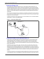
Infrastructure Wireless LAN
The IronPoint 250 is designed to provide access to a wired LAN for wireless workstations. An
integrated wired/wireless LAN is called an Infrastructure configuration. A Basic Service Set (BSS)
consists of a group of wireless PC users and an access point that is directly connected to the wired
LAN. Each wireless station in this BSS can communicate with any device in its wireless group via a
radio link, or access other computers or network resources in the wired LAN infrastructure via the
access point.
The infrastructure configuration not only extends the accessibility of wireless PCs to the wired LAN,
but also increases the effective wireless transmission range for wireless PCs by passing their signal
through one or more access points.
A wireless infrastructure can be used for access to a central database, or for a connection between
mobile workers, as shown in the following figure.
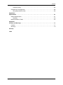
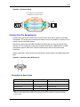
Figure 3-1. Infrastructure Wireless LAN
Wired LAN Extension to
Wireless Clients
Server
Desktop PC
Notebook with Wireless
PC Card Adapter
Switch
Access Point
PC with Wireless
PCI Adapter
Infrastructure Wireless LAN for Roaming Wireless PCs
The Basic Service Set (BSS) defines the communications domain for each access point and its
associated wireless clients. The BSS ID is a 48-bit binary number based on the access point’s
wireless MAC address, and is set automatically and transparently as clients associate with the
access point. The BSS ID is used in frames sent between the access point and its clients to identify
traffic in the service area.
The BSS ID is only set by the access point, never by its clients. The clients only need to set the
Service Set Identifier (SSID) that identifies the service set provided by one or more access points.
The SSID can be manually configured by the clients, can be detected in an access point’s beacon, or
can be obtained by querying for the identity of the nearest access point. For clients that do not need
to roam, set the SSID for the wireless card to that used by the access point to which you want to
connect.
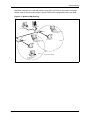
A wireless infrastructure can also support roaming for mobile workers. More than one access point
can be configured to create an Extended Service Set (ESS). By placing the access points so that a
3-2
© 2007 Foundry Networks, Inc.
August 2007
Network Planning
continuous coverage area is created, wireless users within this ESS can roam freely. All wireless
network cards and access points within a specific ESS must be configured with the same SSID.
Figure 3-2. Wireless LAN Roaming
Server
Desktop PC
Notebook with Wireless
PC Card Adapter
Switch
Access Point
Notebook with Wireless
PC Card Adapter
Switch
<BSS2>
Access Point
<ESS>
<BSS1>
Seamless Roaming
PC with Wireless
PCI Adapter
August 2007
© 2007 Foundry Networks, Inc.
3-3
Foundry IronPoint 250 Installation Guide
3-4
© 2007 Foundry Networks, Inc.
August 2007
Chapter 4
Installing the IronPoint 250 Access Point
This section presents procedures for installing the IronPoint 250 access point.
Unpacking the IronPoint Access Point
Unpack the IronPoint 250 access point and make sure the following components are included in the
box:
•
One IronPoint 250 access point
•
One External Power supply and power cable
•
RS-232 console cable
•
IronPoint 250 access point mounting bracket with lock clamp
•
Ceiling tile mounting clamp
•
CD-ROM containing the IronPoint Access Point manuals, drivers, and utility
•
4 adhesive feet
Installing the IronPoint Access Point
Select a location to install the IronPoint 250 access point. The best location is at the center of your
wireless coverage area, within the line of sight of all wireless devices. The access point can be
placed on a horizontal surface or mounted on the wall, with or without the mounting bracket. It can
also be mounted on a suspended ceiling.
WARNING: This product is suitable for use in environmental air space in accordance with the
Section 300-22(c) of the National Electric Code (NEC) and Sections 2- 128.12 - 010 (3) and 12 - 100
of the Canadian Electrical Code. Part 1. C22. 1. For other countries, consult local authorities for
regulations.
WARNING: Any Fast Ethernet (FE) cables installed in air-handling spaces should be suitable under
NEC Article 800.50 and marked accordingly for use in plenums and air-handling spaces with regard
to smoke propagation, such as CL2-P, CL3-P, MPP (Multi Purpose Plenum), or CMP
(Communications Plenum).
August 2007
© 2007 Foundry Networks, Inc.
4-1
Foundry IronPoint 250 Installation Guide
CAUTION: When mounting the access point on a wall or suspended ceiling, use PoE power ONLY.
Do not use the AC power adapter.
Note: For safety reasons, make sure ventilation holes on the access point are positioned
horizontally, not vertically. Allow at least 1 inch (2.54 centimeters) clearance around the ventilation
holes for proper ventilation.
Placing the Access Point on a Desktop or Shelf
Do the following if you want to mount the access point on a horizontal surface, such as a desktop or
shelf:
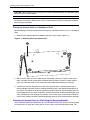
1. Attach the four adhesive feet to the bottom panel of the access point (Figure 4-1).
Figure 4-1. Attaching Feet to the Access Point
2. Set the access point on its four rubber feet on the desktop, shelf, or flat surface, making sure
there is enough clearance around the ventilation holes for proper air flow. For safety reasons,
make sure ventilation holes on the access point are positioned horizontally, not vertically.
3.
Position the antennas along the same axes. Each antenna emits a radiation pattern that is
toroidal (doughnut shaped), with the coverage extending most in the direction perpendicular to
the antenna. Therefore, the antennas should be oriented so that the radio coverage pattern fills
the intended service area. Also, the diversity antennas should both be positioned along the same
axes, providing the same coverage. For example, if the access point is mounted on a horizontal
surface, both antennas should be positioned pointing vertically up to provide optimum coverage.
Attaching the Access Point to a Wall Using the Mounting Bracket
The access point should be mounted only to a wall or wood surface that is at least 1/2-inch plywood
or its equivalent. To mount the access point on a wall, always use its wall-mounting bracket. The
4-2
© 2007 Foundry Networks, Inc.
August 2007
Installing the IronPoint 250 Access Point
access point must be mounted with the RJ-45 cable connector oriented upwards to ensure proper
operation.
Do the following to attach the access point to the wall using the mounting bracket:
1. Using the mounting bracket, mark the position of the four screw holes on the wall. For concrete or
brick walls, you will need to drill holes and insert wall plugs for the screws.
2. Position the mounting bracket over the wall screw holes, then insert the included screws and
tighten them down to secure the bracket firmly to the wall. Use 5/8-inch number 12 wood screws
or a near equivalent (not included in the package contents).
3. Attach the access point to the mounting bracket. Line up the two mounting points on the bracket
with the two mounting slots on the bottom of the access point (see the following figure). Place the
mounting points of the bracket into the mounting slots of the bracket, slide it into position so that
the bracket fastening screw on the access point lines up with the tab on the bracket. Then screw
down the fastening screw to secure the access point to the bracket.
Figure 4-2. Installing the Access Point on the Mounting Bracket
Fastening Screw
Mounting Points
Align this tab with the
Fastening Screw
Bracket
Mounting Slots
4.
Position the antennas along the same axes. Each antenna emits a radiation pattern that is
toroidal (doughnut shaped), with the coverage extending most in the direction perpendicular to
the antenna. Therefore, the antennas should be oriented so that the radio coverage pattern fills
the intended service area. Also, the diversity antennas should both be positioned along the same
August 2007
© 2007 Foundry Networks, Inc.
4-3
Foundry IronPoint 250 Installation Guide
axes, providing the same coverage. For example, if the access point is mounted on a horizontal
surface, both antennas should be positioned pointing vertically up to provide optimum coverage.
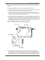
Attaching the Access Point to a Suspended Ceiling
To mount the access point to a suspended ceiling T-rail (Figure 4-4), do the following:
1. Attach the plastic ceiling tile mounting clamp to the mounting bracket (Figure 4-3) using the two
included screws. Note that the ceiling-mount clamp can be attached to the bracket in two
orientations.
Figure 4-3. Attaching the Ceiling-Mount Clamp to the Mounting Bracket
Mounting Holders
Mounting Clip
Fastening Screws
2. Attach the access point to the mounting bracket by aligning the two mounting points on the
bracket with the two mounting slots on the bottom of the access point (Figure 4-2). Then screw
down the fastening screw to secure the access point to the bracket.
3. Choose a location on a ceiling T-rail where the access point will be installed and position the
ceiling-mount clamp holders on either side of the T-rail.
4. Turn the access point until the two clips lock the T-rail into the mounting holders.
5. For best coverage, position the antennas along the same axes.
4-4
© 2007 Foundry Networks, Inc.
August 2007
Installing the IronPoint 250 Access Point
Figure 4-4. Attaching the Bracket to a Suspended Ceiling
Position T-rail between
mounting holders
Push access point up
onto T-rail, then turn
Clips lock T-rail into
mounting holders
Locking the Access Point
To prevent unauthorized removal of the access point, you can use a Kensington Slim MicroSaver
security cable (not included) to attach the access point to a fixed object.
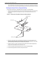
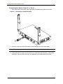
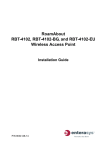
Installing an External Antenna
You can install an external antenna to extend the access point's coverage area. If you install the
external antenna while live sessions are on the access point, those sessions will be terminated.
Professional Installed Device — Must not be distributed through retail stores: You must use
the appropriate antennas, cables, and where applicable, surge arrestors, for your given region. You
are responsible for verifying local regulations or legislation that may impose restrictions on the use of
August 2007
© 2007 Foundry Networks, Inc.
4-5
Foundry IronPoint 250 Installation Guide
specific antenna and cable combinations. For this reason, you must consult with a professional
installer who is trained in RF installation and knowledgeable in the local regulations prior to
connecting an external antenna to your wireless radio product. It is the responsibility of the end user
to ensure that the antenna installation complies with the local radio regulations.
To install an external antenna:
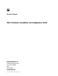
1. Connect the external antenna’s Reverse SMA connector to the access point’s external antenna
connector. Connect 2.4 GHz antennas to the connector labeled "802.11b/g" and 5.0 GHz
antennas to the connector labeled "802.11a."
Figure 4-5. Connecting the External Antenna
Lock
802.11b/g
802.11a
DC 48V / 0.38A
POE In
Reset
Console
External Antenna
Connector
(802.11b/g Radio)
External Antenna
Connector
(802.11a Radio)
2. Set the Antenna Mode for the radio interface to "external" using the CLI or Web interface.
3. Enable the radio interface using the CLI or Web interface.
Powering Up the Access Point
Prepare the access point for power up by doing the following:
1. Connect the RS-232 console cable to the access point’s console port.
Note: The IronPoint access point also supports power over Ethernet (PoE) to obtain its power
from the RJ-45 port.
2. Connect the other end of the RS-232 console cable to your PC's serial port.
4-6
© 2007 Foundry Networks, Inc.
August 2007
Installing the IronPoint 250 Access Point
3. On your PC console application configure the following communication parameters:
•
9600 bits per second
•
8 data bits
•
No parity
•
1 stop bits
•
No Flow Control
4. Connect the power adapter cable to the 48V DC power socket on the access point and the other
end of the cable to a power source.
CAUTION: Use ONLY the power adapter supplied with this access point. Otherwise, the product
may be damaged.
Adding the IronPoint Access Point to the Network
The access point’s country code and TCP/IP address information must be configured before an
access point can be managed or added to a network. Configuring the correct country code allows
the access point to use the necessary channels and frequencies assigned to your country's wireless
frequency regulations. This must be done prior to using the access point for the first time as the
802.11a and 802.11b/g radios cannot be enabled until the country code has been configured.
Note: Country regulations for wireless products differ from country to country. The access points
may be shipped with the country code already preset, as required by the country, or set to the
default setting of "99." If your country code is pre-set (for example, for United States, Canada,
Japan, and New Zealand), you are prohibited from changing this setting. If country code on your
access point is set to "99," then you may set the country code, but you can set it only to the country
in which the access point is to be used.
It is very important to follow these instructions carefully. Selection of the wrong country code for your
device could result in the device operating outside of authorized frequency/power allocations and
lead to possible legal action by the regulatory authority in your country.
Although Foundry has attempted to provide accurate information in these materials, Foundry
assumes no legal responsibility for the accuracy or completeness of the information. Please note
that Foundry's product information does not constitute or contain any guarantee, warranty or legally
binding representation, unless expressly identified as such in a duly signed writing.
Foundry's IronPoint access point uses TCP/IP to communicate with the management consoles. By
using TCP/IP, you can place access points anywhere in the enterprise and manage them from a
single central location. IronPoint access points do not need to be physically connected to any
wireless LAN switch to be managed.
You can configure the access point’s TCP/IP address information using the Automatic Discovery and
Configuration (ADC) or without using ADC. ADC allows you to rapidly configure a number of access
points, straight out of the box, by mapping an access point’s MAC address to an IP address, subnet
mask, and default gateway that are defined on an IronPoint-FES interface. Once the access point is
August 2007
© 2007 Foundry Networks, Inc.
4-7
Foundry IronPoint 250 Installation Guide
attached to the IronPoint-FES, the switch assigns the predefined IP address, subnet mask, and
default gateway to the access point with the matching MAC address.
The IronPoint 250 is shipped with the ADC feature enabled. If you want to use ADC to configure
TCP/IP address information, refer to the Foundry IronPoint Wireless LAN Configuration Guide for the
IronPoint-FastIron Edge Switch for details.
If you do not want to use ADC, you must override ADC at power-up, so you can enter TCP/IP
information. Do the following:
1. Once the access point powers up, a prompt to override ADC appears. Enter the following ADC
override login ID and password on your PC console to override ADC:
ADC-Override-Login: admin
ADC-Override-Password: admin
2. Enter the default administrator user name and password on to gain access to the CLI:
Username: admin
Password: admin
3. Disable ADC by entering the following command:
Foundry AP#configure
Foundry AP(config)#no adc enable
Foundry AP(config)#end
Note: If you do not disable ADC, the ADC-Override Login prompt will keep appearing every time
the access point reboots.
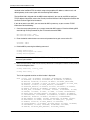
4. Set the correct country code with the country command. For example, to set the country code to
the United Kingdom, enter:
Foundry AP#country <country_code>
Foundry AP# country ?
The list of supported countries and their codes is displayed:
WORD
4-8
Country code: AL-ALBANIA, DZ-ALGERIA, AR-ARGENTINA, AM-ARMENIA,
AU-AUSTRALIA, AT-AUSTRIA, AZ-AZERBAIJAN, BH-BAHRAIN, BY-BELARUS,
BE-BELGIUM, BZ-BELIZE, BO-BOLVIA, BR-BRAZIL, BN-BRUNEI_DARUSSALAM,
BG-BULGARIA, CA-CANADA, CL-CHILE, CN-CHINA, CO-COLOMBIA, CR-COSTA_RICA,
HR-CROATIA, CY-CYPRUS, CZ-CZECH_REPUBLIC, DK-DENMARK,
DO-DOMINICAN_REPUBLIC, EC-ECUADOR, EG-EGYPT, EE-ESTONIA, FI-FINLAND,
FR-FRANCE, GE-GEORGIA, DE-GERMANY, GR-GREECE, GT-GUATEMALA,
HK-HONG_KONG, HU-HUNGARY, IS-ICELAND, IN-INDIA, ID-INDONESIA, IR-IRAN,
IE-IRELAND, IL-ISRAEL, IT-ITALY, JP-JAPAN, JO-JORDAN, KZ-KAZAKHSTAN,
KP-NORTH KOREA, KR-KOREA_REPUBLIC, KW-KUWAIT, LV-LATVIA, LB-LEBANON,
LI-LIECHTENSTEIN, LT-LITHUANIA, LU-LUXEMBOURG, MO-MACAU, MK-MACEDONIA,
MY-MALAYSIA, MX-MEXICO, MC-MONACO, MA-MOROCCO, NL-NETHERLANDS,
NZ-NEW_ZEALAND, NO-NORWAY, OM-OMAN, PK-PAKISTAN, PA-PANAMA, PE-PERU,
PH-PHILIPPINES, PL-POLAND, PT-PORTUGAL, PR-PUERTO_RICO, QA-QATAR,
RO-ROMANIA, RU-RUSSIA, SA-SAUDI_ARABIA, SG-SINGAPORE,
SK-SLOVAK_REPUBLIC, SI-SLOVENIA, ZA-SOUTH_AFRICA, ES-SPAIN, SE-SWEDEN,
CH-SWITZERLAND, SY-SYRIA, TW-TAIWAN, TH-THAILAND, TR-TURKEY,
UA-UKRAINE, AE-UNITED_ARAB_EMIRATES, GB-UNITED_KINGDOM,
© 2007 Foundry Networks, Inc.
August 2007
Installing the IronPoint 250 Access Point
US-UNITED_STATES, UY-URUGUAY, VE-VENEZUELA, VN-VIETNAM
5. Configure the TCP/IP address. The default IP address for the access point is 169.254.1.1 with a
255.255.0.0 subnet mask and a default gateway of 169.254.1.254. To change the access point's
IP address, for example, to 192.168.1.10 with a 24-bit subnet mask and a default gateway of
192.168.1.254, enter:
Foundry
Foundry
Foundry
Foundry
Foundry
AP#configure
AP(config)#interface ethernet
AP(if-ethernet)#ip address 192.168.1.10 255.255.255.0 192.168.1.254
AP(if-ethernet)#end
AP #
Syntax: interface ethernet
ip address <ip-address> <subnet-mask> <default-gateway>
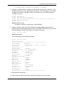
6. Confirm the Country Code and TCP/IP settings with the show system command. Do not
proceed unless the information displayed is correct. For example, to confirm the country code of
the United Kingdom and the TCP/IP address of 192.168.8.10/24, enter:
Foundry
AP # show system
Syntax: show system
The command displays the following information:
Foundry
AP # show system
System Information
============================================================
Serial Number
: SACC1200KA
System Up time
: 0 days, 0 hours, 5 minutes, 25 seconds
System Name
: Foundry AP
System Location
:
System Contact
: Contact
System Country Code
: GB - UNITED KINGDOM
MAC Address
: 00-0C-DB-813-882
IP Address
: 192.168.8.10
Subnet Mask
: 255.255.255.0
Default Gateway
: 192.168.8.254
VLAN State
: DISABLED
Management VLAN ID(AP): 1
IAPP State
: ENABLED
DHCP Client
: DISABLED
HTTP Server
: ENABLED
HTTP Server Port
: 80
HTTPS Server
: ENABLED
HTTPS Server Port
: 443
Slot Status
: Dual band(a/g)
Software Version
: 01.2.03.00Tw8
SSH Server
: ENABLED
SSH Server Port
: 22
Telnet Server
: ENABLED
============================================================
7. Power down the access point.
8. Connect one end of the Ethernet cable to the RJ-45 connector on the access point.
August 2007
© 2007 Foundry Networks, Inc.
4-9
Foundry IronPoint 250 Installation Guide
9. Connect the other end of the cable to the network subnet for which the access point was
programmed.
10. Power up the access point. It can now be managed using its command line interface (CLI) or
Web interface.
Once the access point is set up with country code and IP address, other parameters can be defined
using one of the following methods:
•
A PC running Internet Explorer version 5.0 (and above) or Firefox Web browser to directly access
an individual Foundry AP’s internal Web management interface.
•
A Telnet or SSH v2 client to directly access Foundry AP’s command line interface (CLI).
Refer to the Foundry IronPoint Access Point User Guide for details.
4-10
© 2007 Foundry Networks, Inc.
August 2007
Chapter 5
Making a Network Connection
Connecting to a Network Device
The IronPoint 250 is designed to connect a wired Ethernet network to wireless clients. It can be
connected to any Ethernet network device, such as a hub or switch.
CAUTION: The IronPoint 250 is only intended for installation in Environment A as defined in
IEEE 802.3af. All interconnected equipment must be contained within the same building, including
the interconnected equipment's associated LAN connection.
Twisted-Pair Cable
The access point’s Ethernet port connection requires an unshielded twisted-pair (UTP) cable with
RJ-45 connectors at both ends. For 100BASE-TX connections, Category 5 or better cable is
required; for 10BASE-T, Category 3 or better cable can be used.
Cabling Guidelines
The RJ-45 port on the access point supports automatic MDI/MDI-X operation, so you can use
straight-through cables for all network connections to PCs, switches, or hubs.
See Appendix B for further information on cabling.
Caution: Do not plug a phone jack connector into the RJ-45 port. This will damage the access point.
Use only twisted-pair cables with RJ-45 connectors that conform to FCC standards.
August 2007
© 2007 Foundry Networks, Inc.
5-1
Foundry IronPoint 250 Installation Guide
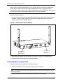
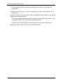
Connecting to a Switch, Hub, PC, or Server
1. Attach one end of a twisted-pair cable segment to the network device’s RJ-45 connector.
Figure 5-1. Connecting to a Network Device
2. Attach the other end of the cable segment to the Ethernet port on the access point.
Note: Make sure the twisted pair cable does not exceed 100 meters (328 ft) in length.
3. As the connection is made, the access point’s Link LED should light indicating a valid network
connection. If the Link LED fails to light, see Appendix A for troubleshooting information.
5-2
© 2007 Foundry Networks, Inc.
August 2007
Appendix A
Troubleshooting
Diagnosing Access Point Indicators
Troubleshooting Chart
Symptom
Action
Status LED is Off
•
External power supply may be disconnected. Check connections between
the access point, the power adapter, and the wall outlet.
•
If using PoE, verify that access point’s RJ-45 port is attached to a PoE
source device, that the PoE source device is powered on, and that PoE
power is enabled on the port attached to the access point.
•
Contact Technical Support.
•
Verify that the access point and attached device is powered on.
•
Be sure the cable is plugged into both the access point and corresponding
device.
•
Verify that the proper cable type is used and its length does not exceed
specified limits.
•
Check the cable connections for possible defects. Replace the cable if
necessary.
Link LED is Off
Installation
Verify that all system components have been properly installed. If one or more components appear
to be malfunctioning (such as the power cord or network cabling), test them in an alternate
environment where you are sure that all the other components are functioning properly.
Console Access
If you cannot access the command line interface via a serial port connection, check the following
items before you contact Technical Support:
•
Be sure you have set the terminal emulator program to VT100 compatible, 8 data bits, 1 stop bit,
no parity and 9600 bps.
•
Check that the serial cable conforms to the pin-out connections provided in Appendix B.
August 2007
© 2007 Foundry Networks, Inc.
A-1
Foundry IronPoint 250 Installation Guide
In-Band Access
If the access point cannot be configured using the CLI via Telnet or SSH v2, a Web browser using
HTTP or HTTPS, or SNMP v2 or v3 software, check the following items before you contact Technical
Support.
If the access point cannot be configured using the CLI via Telnet, a Web browser, or SNMP software,
check the following items before you contact Technical Support:
•
Be sure to have configured the access point with a valid IP address, subnet mask and default
gateway.
•
If VLANs are enabled on the access point, the management station should be configured to send
tagged frames with a VLAN ID that matches the access point’s native VLAN (default VLAN 1).
However, to manage the access point from a wireless client, the AP Management Filter should
be disabled.
•
Check that you have a valid network connection to the access point and that the Ethernet port or
the wireless interface that you are using has not been disabled.
•
If you are connecting to the access point through the wired Ethernet interface, check the network
cabling between the management station and the access point. If you are connecting to access
point from a wireless client, ensure that you have a valid connection to the access point.
•
If you cannot connect using Telnet, you may have exceeded the maximum number of concurrent
Telnet sessions permitted (i.e, four sessions). Try connecting again at a later time.
Wireless Client Network Access
If wireless clients cannot access the network, check the following before you contact Technical
Support:
A-2
•
Be sure the access point and the wireless clients are configured with the same Service Set ID
(SSID).
•
If authentication or encryption are enabled, ensure that the wireless clients are properly
configured with the appropriate pre-shared key, authentication, or encryption keys. The wireless
client's NIC must have the necessary drivers to support the security and authentication methods
configured on the access point.
•
If authentication is being performed through a RADIUS server, ensure that the clients are properly
configured on the RADIUS server.
•
If authentication is being performed through IEEE 802.1x, be sure the wireless users have
installed and properly configured 802.1x client software.
•
If MAC address filtering is enabled, be sure the client’s address is included in the local filtering
database or on the RADIUS server database.
•
If the wireless clients are roaming between access points, make sure that all the access points
and wireless devices in the Extended Service Set (ESS) are configured to the same SSID, and
authentication method.
© 2007 Foundry Networks, Inc.
August 2007
Troubleshooting
•
Check the configuration matrix for the most commonly used authentication and encryption
combinations in the Quick Installation and Getting Started Guide to ensure that the access point
is correctly configured.
Lost Password
The only way to recover a lost password is by setting the access point to its default configuration.
Refer to the section “Reset the Access Point Default Settings” for instructions.
Reset the Access Point Default Settings
If all other recovery measures fail and the access point is still not functioning properly, take any of
these steps:
•
Reset the access point’s hardware using the console interface, Web interface, or through a power
reset.
•
Reset the access point to its default configuration by pressing the reset button on the back panel
for 5 seconds or more. Then use the default user name “admin” with the password “admin” to
access the management interface.
August 2007
© 2007 Foundry Networks, Inc.
A-3
Foundry IronPoint 250 Installation Guide
A-4
© 2007 Foundry Networks, Inc.
August 2007
Appendix B
Cables
Specifications
Cable Types and Specifications
Cable
Type
Max. Length
Connector
10BASE-T
Cat. 3 or better 100-ohm UTP
100 m (328 ft)
RJ-45
100BASE-TX
Cat. 5 or better 100-ohm UTP
100 m (328 ft)
RJ-45
Twisted-Pair Cable and Pin Assignments
CAUTION: DO NOT plug a phone jack connector into any RJ-45 port. Use only twisted-pair cables
with RJ-45 connectors that conform with FCC standards.
For 100BASE-TX/10BASE-T connections, a twisted-pair cable must have two pairs of wires. Each
wire pair is identified by two different colors. For example, one wire might be green and the other,
green with white stripes. Also, an RJ-45 connector must be attached to both ends of the cable.
CAUTION: Each wire pair must be attached to the RJ-45 connectors in a specific orientation.
Figure B-1 illustrates how the pins on the RJ-45 connector are numbered. Be sure to hold the
connectors in the same orientation when attaching the wires to the pins.
Figure B-1. RJ-45 Connector Pin Numbers
8
1
August 2007
8
1
© 2007 Foundry Networks, Inc.
B-1
Foundry IronPoint 250 Installation Guide
100BASE-TX/10BASE-T Pin Assignments
Use unshielded twisted-pair (UTP) or shielded twisted-pair (STP) cable for RJ-45 connections:
100-ohm Category 3 or better cable for 10 Mbps connections, or 100-ohm Category 5 or better cable
for 100 Mbps connections. Also be sure that the length of any twisted-pair connection does not
exceed 100 meters (328 feet).
The RJ-45 port on the access point supports automatic MDI/MDI-X operation, so you can use
straight-through or crossover cables for all network connections to PCs, switches, or hubs.
Pin
MDI Signal Name
MDI-X Signal Name
1
Receive Data plus (RD+)
and GND (Positive Vport)
Transmit Data plus (TD+)
and -48V feeding power (Negative Vport)
2
Receive Data minus (RD-)
and GND (Positive Vport)
Transmit Data minus (TD-)
and -48V feeding power (Negative Vport)
3
Transmit Data minus (TD+)
and -48V feeding power (Negative Vport)
Receive Data plus (RD+)
and GND (Positive Vport)
4
GND (Positive Vport)
-48V feeding power (Negative Vport)
5
GND (Positive Vport)
-48V feeding power (Negative Vport)
6
Transmit Data minus (TD-)
and -48V feeding power (Negative Vport)
Receive Data minus (RD-)
and GND (Positive Vport)
7
-48V feeding power (Negative Vport)
GND (Positive Vport
8
-48V feeding power (Negative Vport)
GND (Positive Vport
Note: The “+” and “-” signs represent the polarity of the wires that make up each wire pair.
Straight-Through Wiring
Because the 10/100 Mbps port on the access point uses automatic MDI/MDI-X pin configuration,
you can use “straight-through” or “crossover” cable for network connections to PCs, hubs or
switches.
Figure B-2. Straight-Through Wiring
EIA/TIA 568B RJ-45 Wiring Standard
10/100BASE-TX Straight-through Cable
White/Orange Stripe
Orange
End A
1
2
3
4
5
6
7
8
White/Green Stripe
Blue
White/Blue Stripe
Green
White/Brown Stripe
1
2
3
4
5
6
7
8
End B
Brown
Crossover Wiring
Because the 10/100 Mbps port on the access point uses automatic MDI/MDI-X pin configuration,
you can use “straight-through” or “crossover” cable for network connections to PCs, hubs or
switches.
B-2
© 2007 Foundry Networks, Inc.
August 2007
Cables
Figure B-3. Crossover Wiring
EIA/TIA 568B RJ-45 Wiring Standard
10/100BASE-TX Crossover Cable
White/Orange Stripe
Orange
1
2
3
4
5
6
7
8
End A
White/Green Stripe
Blue
White/Blue Stripe
Green
White/Brown Stripe
1
2
3
4
5
6
7
8
End B
Brown
Console Port Pin Assignments
The DB-9 serial port on the IronPoint 250 is used to connect to the access point for out-of-band
management. The access point’s command-line interface can be accessed from a terminal or a PC
running a terminal emulation program.
Connect the console cable (included) to the RS-232 console port to access the command-line
interface. You can manage the access point using the console port, the Web interface, or SNMP
management software. Refer to the Foundry IronPoint Access Point User Guide for more
information.
The pin assignments used to connect to the console port are described in the following figure and
table.
Figure B-4. Serial Port (DB-9 DTE) Pin-Out
1
6
5
9
Wiring Map for Serial Cable
Signal (access point serial port)
Null Modem Cable
Signal (management console port)
2 RXD (receive data)
<---------RXD ------------
3 TXD (transmit data)
3 TXD (transmit data)
-----------TXD ---------->
2 RXD (receive data)
5 GND (ground)
-----------GND ----------
5 GND (ground)
1,4,6,7,8,9 Unused
1,4,6,7,8,9 Unused
Note: The left hand column pin assignments are for the male DB-9 connector on the access point. Pin 3
(TXD or “transmit data”) must emerge on the management console’s end of the connection as RXD
(“receive data”).
August 2007
© 2007 Foundry Networks, Inc.
B-3
Foundry IronPoint 250 Installation Guide
The serial port’s configuration requirements are as follows:
B-4
•
Default Baud rate—9,600 bps
•
Character Size—8 Characters
•
Parity—None
•
Stop bit—One
•
Data bits—8
© 2007 Foundry Networks, Inc.
August 2007
Appendix C
Specifications
General Specifications
Maximum Channels
802.11a:
US & Canada: 10 (normal mode), 3 (turbo mode)
Japan: 4 (normal mode), 1 (turbo mode)
ETSI: 4 channels (normal mode), 1 (turbo mode)
Taiwan: 4 (normal mode), 1 (turbo mode)
802.11g:
FCC/IC: 1-11
ETSI: 1-13
France: 10-13
MKK: 1-14
Taiwan: 1-11
Maximum Clients
64 per VAP interface
Operating Range
See “Maximum Distance Tables” on page C-5.”
Data Rate
802.11a:
Normal Mode: 6, 9, 12, 18, 24, 36, 48, 54 Mbps per channel
Turbo Mode: 12, 18, 24, 36, 48, 72, 96, 108 Mbps per channel
802.11g: 6, 9, 12, 18, 24, 36, 48, 54 Mbps per channel
802.11b: 1, 2, 5.5, 11 Mbps per channel
Modulation Type
802.11a: BPSK, QPSK, 16-QAM, 64-QAM
802.11g: CCK, BPSK, QPSK, OFDM
802.11b: CCK, BPSK, QPSK
Network Configuration
Infrastructure
Operating Frequency
802.11a:
5.15 ~ 5.25 GHz (lower band) US/Canada, Japan
5.725 ~ 5.825 GHz (upper band) US/Canada
August 2007
© 2007 Foundry Networks, Inc.
C-1
Foundry IronPoint 250 Installation Guide
5.50 ~ 5.70 GHz Europe
5.25 ~ 5.35 GHz (middle band) Taiwan
5.725 ~ 5.825 GHz (high band) Taiwan
802.11b/g:
2.4 ~ 2.4835 GHz (US, Canada, ETSI)
2.4 ~ 2.497 GHz (Japan)
2.400 ~ 2.4835 GHz (Taiwan)
AC Power supply
Input: 100-240 VAC, 50-60 Hz
Output: 48 VDC, 0.38 A
Unit Power Supply
DC Input: 48 VDC, 0.38 A maximum
Input voltage: 48 volts, 0.27 A, 12.95 watts
Power consumption: 9.6 watts maximum
PoE (DC)
Input voltage: -48 VDC, 0.27 A, 12.96 watts
Note: Power can also be provided to the access point through the Ethernet port based on
IEEE 802.3af Power over Ethernet (PoE) specifications. When both PoE is provided and the AC
adapter is plugged in, power will taken from the PoE source.
Physical Size
21.83 x 13.73 x 3.27 cm (8.60 x 5.40 x 1.29 in)
Weight
0.687 kg (1.514 lbs)
LED Indicators
Status (power), Ethernet (link/activity), Radio a
and Radio b/g (wireless link/activity)
Network Management
Web-browser, RS232 console, Telnet, SSH, SNMP
Temperature
Operating: -5 to 50 °C (23 to 122 °F)
Storage: 0 to 70 °C (32 to 158 °F)
Humidity
15% to 95% (non-condensing)
EMC Certification
FCC Part 15. Subpart B (Class B)
EN 55022 (CE mark) (Class B)
EN 55024 (CE mark) (Immunity) for Information Technology Equipment
ICES-003 (Canada) (Class B)
AS/NZ 55022 (Australia) (Class B)
VCCI (Japan) (Class B)
EN 61000-3-2
EN 61000-3-3
EN 61000-6-1
C-2
© 2007 Foundry Networks, Inc.
August 2007
Specifications
Radio Signal Certification
FCC Part 15, Subpart C - Intentional Radiators 15.247, 15.207, 15.407
RSS-210 (Canada)
RSS-102 (Canada)
EN 300 328, EN 300 893, EN 301 489 (Sections 1-17, as necessary) (Europe)
ARIB STD 33 (Japan)
ARIB STD 66 (Japan)
ARIB STD T71 (Japan)
AS/NZS 4771, 4628.2 (Australia and New Zealand)
Safety
UL/CUL (CSA 22.2 No. 60950-1 & UL60950-1)
EN 60950-1 (TÜV/GS)
IEC 60950-1 (CB)
Standards
IEEE 802.3-2005
IEEE 802.11a, b, g
August 2007
© 2007 Foundry Networks, Inc.
C-3
Foundry IronPoint 250 Installation Guide
Sensitivity
IEEE 802.11a
Modulation/Rates
Sensitivity (GHz - dBm)
5.15-5.250
5.25-5.350
5.50-5.700
5.725-5.825
BPSK (6 Mbps)
-88
-88
-88
-88
BPSK (9 Mbps)
-87
-87
-87
-87
QPSK (12 Mbps)
-86
-86
-86
-86
QPSK (18 Mbps)
-83
-83
-83
-83
16 QAM (24 Mbps)
-80
-80
-80
-80
16 QAM (36 Mbps)
-76
-76
-76
-76
64 QAM (48 Mbps)
-73
-73
-73
-73
64QAM(54 Mbps)
-70
-70
-70
-70
IEEE 802.11g
Data Rate
Sensitivity (dBm)
6 Mbps
-88
9 Mbps
-86
12 Mbps
-85
17 Mbps
-84
24 Mbps
-80
36 Mbps
-76
48 Mbps
-73
54 Mbps
-70
IEEE 802.11b
Data Rate
C-4
Sensitivity (dBm)
1 Mbps
-90
2 Mbps
-89
5.5 Mbps
-87
11 Mbps
-85
© 2007 Foundry Networks, Inc.
August 2007
Specifications
Maximum Distance Tables
Important Notice
The operating range distances listed in the following tables are for typical environments only.
Operating ranges can vary considerably depending on factors such as local interference and barrier
composition. It is recommended to do a site survey to determine the maximum ranges for specific
access point locations in your environment.
802.11a Wireless Distance Table
Environment
Office
Speed and Distance Ranges
54
Mbps
48
Mbps
36
Mbps
24
Mbps
18
Mbps
12
Mbps
9
Mbps
6
Mbps
27 m
89 ft
40 m
132 ft
46 m
152 ft
55 m
182 ft
60 m
198 ft
66 m
76 m
80 m
218 ft
251 ft
264 ft
802.11b Wireless Distance Table
Speed and Distance Ranges
Environment
11 Mbps
5.5 Mbps
2 Mbps
1 Mbps
Office
70 m
230 ft
75 m
246 ft
85 m
279 ft
85 m
279 ft
802.11g Wireless Distance Table
Environ- Speed and Distance Ranges
ment
Office
54
Mbps
48
Mbps
36
Mbps
24
Mbps
18
Mbps
12
Mbps
11
Mbps
9
Mbps
6
Mbps
5
Mbps
2
Mbps
1
Mbps
43 m
141 ft
50 m
164 ft
57 m
187 ft
63 m
207 ft
67 m
220 ft
71 m
233 ft
75 m
246 ft
77 m
253 ft
81 m
266 ft
85 m
279 ft
85 m
279 ft
85 m
279ft
Note: Office Environment: A typical office or home environment with floor to ceiling obstructions
between the access point and clients.
August 2007
© 2007 Foundry Networks, Inc.
C-5
Foundry IronPoint 250 Installation Guide
C-6
© 2007 Foundry Networks, Inc.
August 2007
Appendix D
Cautions and Warnings
The cautions and warnings that appear in this manual are listed below in English, German, French,
and Spanish.
Cautions
A caution calls your attention to a possible hazard that can damage equipment.
"Vorsicht” weist auf die Gefahr einer möglichen Beschädigung des Gerätes in.
Une mise en garde attire votre attention sur un risque possible d'endommagement de l'équipement.
Ci-dessous, vous trouverez les mises en garde utilisées dans ce manuel.
Un mensaje de precaución le advierte sobre un posible peligro que pueda dañar el equipo. Las
siguientes son precauciones utilizadas en este manual.
CAUTION:
Use only the power adapter supplied with the access point. Otherwise, the
product may be damaged.
VORSICHT:
Nur der mit dem Access Point mitgelieferte Netzstromadapter darf verwendet
werden. Anderenfalls kann das Produkt Schaden davontragen.
MISE EN GARDE:
Utiliser uniquement l’adaptateur secteur fourni avec le point d’accès, faute de
quoi le produit risque d’être endommagé.
PRECAUCIÓN:
Utilice solamente el adaptador de alimentación suministrado con el punto de
acceso. De otro modo, el producto podría resultar dañado.
CAUTION:
Do not plug a phone jack connector into any RJ-45 port. Use only twisted-pair
cables with RJ-45 connectors that conform with FCC standards.
VORSICHT:
Keinen Telefonstecker an einer RJ-45-Schnittstelle anschließen. Nur TP
(Twisted Pair)-Kabel mit RJ-45-Konnektoren, die FCC-Normen entsprechen,
verwenden.
MISE EN GARDE:
Ne pas tenter de brancher un connecteur différent du modèle RJ-45 dans un
port RJ-45. Utiliser uniquement à cet effet des câbles en paires torsadées
dotés de connecteurs RJ-45 conformes aux standards de la FCC.
August 2007
© 2007 Foundry Networks, Inc.
D-1
Foundry IronPoint 200 Installation Guide
D-2
PRECAUCIÓN:
No enchufe una clavija de teléfono en un puerto RJ-45. Utilice solamente
cables de par trenzado con conectores RJ-45 que se ajusten a la normativa
FCC.
CAUTION:
Each wire pair must be attached to the RJ-45 connector in a specific
orientation.
VORSICHT:
Jedes Leiterpaar muss in einer bestimmten Ausrichtung am RJ-45-Anschluss
angeschlossen werden.
MISE EN GARDE:
Le connecteur RJ-45 d’un câble en paires torsadées correspond à un câblage
et à un positionnement précis.
PRECAUCIÓN:
Cada par de cables debe acoplarse al conector RJ-45 conforme a una
determinada orientación.
CAUTION:
When mounting the access point on a wall or suspended ceiling, use PoE
power ONLY. Do not use the AC power adapter.
VORSICHT:
Bei Installation des Access Point an einer Wand oder einem Hängeboden darf
NUR PoE (Power over Ethernet)-Strom verwendet werden. Keinen
Wechselstromadapter verwenden.
MISE EN GARDE:
En cas de montage du point d’accès sur un mur ou en plafond suspendu,
utiliser UNIQUEMENT une alimentation en PoE (Power over Ethernet). Ne
pas utiliser l’adaptateur secteur.
PRECAUCIÓN:
Al montar el punto de acceso en una pared o techo, utilice alimentación por
Ethernet (PoE) SOLAMENTE. No utilice el adaptador de alimentación de CA.
© 2007 Foundry Networks, Inc.
August 2007
Cautions and Warnings
CAUTION:
The IronPoint 250 is only intended for installation in Environment A as defined
in IEEE 802.3af. All interconnected equipment must be contained within the
same building, including the interconnected equipment's associated LAN
connection.
VORSICHT:
IronPoint 250 ist nur zur Installation in einer Umgebung A, wie in IEEE
802.3af definiert, bestimmt. Alle verbundenen Geräte müssen sich im
gleichen Gebäude befinden, einschließlich der zugehörige LAN-Anschluss
der verbundenen Geräte.
MISE EN GARDE:
Le modèle IronPoint 250 est uniquement destiné à une installation en
environnement A, comme défini dans la norme IEEE 802.3af relative à
l’alimentation par câble Ethernet. Tous les équipements interconnectés
doivent se trouver dans le même bâtiment, y compris les connexions au
réseau local qui leur sont associées.
PRECAUCIÓN:
El punto IronPoint 250 está diseñado exclusivamente para su instalación en
un Entorno A, conforme éste aparece definido en la norma IEEE 802.3af.
Todo el equipo interconectado debe estar contenido en el mismo edificio,
incluyendo la conexión LAN asociada.
Warnings
A warning calls your attention to a possible hazard that can cause injury or death. The following are
the warnings used in this manual.
"Achtung" weist auf eine mögliche Gefährdung hin, die zu Verletzungen oder Tod führen können. Sie
finden die folgenden Warnhinweise in diesem Handbuch:
Un avertissement attire votre attention sur un risque possible de blessure ou de décès. Ci-dessous,
vous trouverez les avertissements utilisés dans ce manuel.
Una advertencia le llama la atención sobre cualquier posible peligro que pueda ocasionar daños
personales o la muerte. A continuación se dan las advertencias utilizadas en este manual.
WARNING:
This product is suitable for use in environmental air space in accordance with
the Section 300-22(c) of the National Electric Code and Sections 2- 128.12 010 (3) and 12 - 100 of the Canadian Electrical Code. Part 1. C22. 1. For other
countries, consult local authorities for regulations.
ACHTUNG!
Dieses Produkt zur Verwendung in einem Umgebungsluftraum gemäß
Abschnitt 300-22(c) des National Electric Code und Abschnitt 2- 128.12 - 010
(3) und 12 - 100 des Canadian Electrical Code Teil 1. C22.1 geeignet. Die
Vorschriften für andere Länder sind bei den örtlichen Behörden erhältlich.
AVERTISSEMENT Cet appareil est adapté à une utilisation dans les vides de construction des
bâtiments selon la section 300-22(c) du code NEC (National Electric Code) et
les sections 2- 128.12 - 010 (3) et 12 - 100 du Code électrique du Canada,
partie 1. C22. 1. Pour tous les autres pays, consulter les organismes de
réglementation locaux.
August 2007
© 2007 Foundry Networks, Inc.
D-3
Foundry IronPoint 200 Installation Guide
ADVERTENCIA
Este producto es adecuado para su uso en el espacio aéreo circundante en
conformidad con la sección 300-22(c) del National Electric Code (Código
Eléctrico Nacional de EE.UU.) y las secciones 2- 128.12 - 010 (3) y 12 - 100 del
Código Eléctrico de Canadá. Parte 1. C22. 1. En otros países, consulte a las
autoridades locales competentes para informarse acerca de las normativas
vigentes.
WARNING:
Any Fast Ethernet (FE) cables installed in air-handling spaces should be
suitable under NEC Article 800.50 and marked accordingly for use in plenums
and air-handling spaces with regard to smoke propagation, such as CL2-P,
CL3-P, MPP (Multi Purpose Plenum), or CMP (Communications Plenum).
ACHTUNG!
Alle Fast-Ethernet (FE)-Kabel, die in Lüftungsräumen installiert werden, sollten
gemäß NEC Artikel 800.50 geeignet sein und entsprechend zur Verwendung in
Hohlräumen (Plenum) und Lüftungsräumen im Hinblick auf Rauchausbreitung
gekennzeichnet sein, z.B. CL2-P, CL3-P, MPP (Multi Purpose Plenum) oder
CMP (Communications Plenum).
AVERTISSEMENT Les câbles Fast Ethernet (FE) installés dans un vide d’air doivent correspondre
aux critères de l’article 800.50 du code NEC et identifiés en conséquence
comme adaptés à une utilisation dans les vides de construction des bâtiments
en matière de propagation de la fumée (marquages CL2-P, CL3-P, MPP (Multi
Purpose Plenum) ou CMP (Communications Plenum)).
ADVERTENCIA
D-4
Todos los cables Fast Ethernet (FE) instalados en espacios aéreos deben
cumplir con el artículo 800.50 del NEC y estar marcados adecuadamente para
su uso en espacios aéreos y plenums en lo concerniente a la propagación de
humo, tales como CL2-P, CL3-P, MPP (Plenum multifuncional), o CMP
(Plenum de comunicaciones).
© 2007 Foundry Networks, Inc.
August 2007
Glossary
10BASE-T
IEEE 802.3 specification for 10 Mbps Ethernet over two pairs of Category 3 or better UTP cable.
100BASE-TX
IEEE 802.3u specification for 100 Mbps Fast Ethernet over two pairs of Category 5 or better UTP
cable.
Access Point
An internetworking device that seamlessly connects wired and wireless networks. Access points
attached to a wired network, support the creation of multiple radio cells that enable roaming
throughout a facility.
Ad Hoc
A group of computers connected as an independent wireless network, without an access point.
Authentication
The process to verify the identity of a client requesting network access. IEEE 802.11 specifies two
forms of authentication: open system and shared key.
Backbone
The core infrastructure of a network. The portion of the network that transports information from one
central location to another central location where it is unloaded onto a local system.
Basic Service Set (BSS)
A coverage area for two or more 802.11-compliant, wireless stations.
CSMA/CA
Carrier Sense Multiple Access with Collision Avoidance.
Distributed System (DS)
Enables mobile device support by providing the logical services necessary to handle address to
destination mapping and seamless integration of multiple BSSs.
August 2007
© 2007 Foundry Networks, Inc.
Glossary-1
Foundry IronPoint 250 Installation Guide
Dynamic Host Configuration Protocol (DHCP)
Provides a framework for passing configuration information to hosts on a TCP/IP network. DHCP is
based on the Bootstrap Protocol (BOOTP), adding the capability of automatic allocation of reusable
network addresses and additional configuration options.
Extended Service Set (ESS)
More than one wireless cell can be configured with the same Service Set Identifier to allow mobile
users can roam between different cells with the Extended Service Set.
Ethernet
A network communication system developed and standardized by DEC, Intel, and Xerox, using
baseband transmission, CSMA/CD access, logical bus topology, and coaxial cable. The successor
IEEE 802.3 standard provides for integration into the OSI model and extends the physical layer and
media with repeaters and implementations that operate on fiber, thin coax and twisted-pair cable.
Fast Ethernet
A 100 Mbps network communication system based on Ethernet and the CSMA/CD access method.
IEEE
Institute of Electrical and Electronic Engineers.
IEEE 802.11a
A wireless standard that supports high-speed communications in the 5 GHz band using Orthogonal
Frequency Division Multiplexing (OFDM). The standard supports data rates of 6, 12, 24, and 54
Mbps.
IEEE 802.11b
A wireless standard that supports wireless communications in the 2.4 GHz band using Direct
Sequence Spread Spectrum (DSSS). The standard provides for data rates of 1, 2, 5.5, and 11 Mbps.
IEEE 802.11g
A wireless standard that supports wireless communications in the 2.4 GHz band using supports
high-speed communications in the 5 GHz band using Orthogonal Frequency Division Multiplexing
(OFDM). The standard provides for data rates of 6, 9, 11, 12, 18, 24, 36, 48, 54 Mbps. IEEE 802.11g
is also backward compatible with IEEE 802.11b.
IEEE 802.1x
Port Authentication controls access to the switch ports by requiring users to first enter a user ID and
password for authentication.
IEEE 802.3
Defines carrier sense multiple access with collision detection (CSMA/CD) access method and
physical layer specifications.
IEEE 802.3u
Defines CSMA/CD access method and physical layer specifications for 100BASE-TX and
100BASE-FX Fast Ethernet.
Infrastructure
An integrated wireless and wired LAN is called an infrastructure configuration.
Glossary-2
© 2007 Foundry Networks, Inc.
August 2007
Glossary
LED
Light emitting diode used for monitoring a device or network condition.
Local Area Network (LAN)
A group of interconnected computer and support devices.
MAC Address
The physical layer address used to uniquely identify network nodes.
Power over Ethernet (PoE)
A specification for providing both power and data to low-power network devices using a single
Category 5 Ethernet cable. PoE provides greater flexibility in the locating of access point’s and
network devices, and significantly decreased installation costs.
RADIUS
A logon authentication protocol that uses software running on a central server to control access to
the network.
RJ-45 Connector
A connector for twisted-pair wiring.
Roaming
A wireless LAN mobile user moves around an ESS and maintains a continuous connection to the
infrastructure network.
Service Set Identifier (SSID)
An identifier that is attached to packets sent over the wireless LAN and functions as a password for
joining a particular radio cell; i.e., Basic Service Set (BSS).
Simple Network Management Protocol (SNMP)
The application protocol in the Internet suite of protocols which offers network management
services.
Transmission Control Protocol/Internet Protocol (TCP/IP)
Protocol suite that includes TCP as the primary transport protocol, and IP as the network layer
protocol.
UTP
Unshielded twisted-pair cable.
Virtual LAN (VLAN)
A Virtual LAN is a collection of network nodes that share the same collision domain regardless of
their physical location or connection point in the network. A VLAN serves as a logical workgroup with
no physical barriers, and allows users to share information and resources as though located on the
same LAN.
August 2007
© 2007 Foundry Networks, Inc.
Glossary-3
Foundry IronPoint 250 Installation Guide
Glossary-4
© 2007 Foundry Networks, Inc.
August 2007
Index
Numerics
E
100BASE-TX ports 2-3
10BASE-T ports 2-3
Ethernet connection 5-1
A
air flow requirements 4-2
antennas, positioning 4-2, 4-3
applications 3-1
infrastructure 3-2
wireless LAN roaming 3-2
B
Basic Service Set See BSS
bracket, wall mount 4-2
BSS 3-2
C
cable
crossover B-2
specifications B-1
straight-through B-2
channels, maximum C-1
clients, maximum C-1
console cable 2-2
console port 2-2, 2-6
pin assignments B-3
crossover cable B-2
CSMA/CA 2-2
D
data rate, options C-1
desktop mounting 4-2
distances, maximum C-5
August 2007
F
features
management 2-7
switch 2-7
front panel of switch 2-1
I
IEEE 802.11a 2-2
indicators, LED 2-5
infrastructure wireless LANs 3-2
installation
connecting devices to the switch 5-2
desktop or shelf mounting 4-2
port connections 5-1
problems A-1
site requirements 4-1
L
LED indicators
problems A-1
location requirements 4-1
M
management
agent 2-2
features 2-7
out-of-band 2-2
SNMP 2-2
Web-based 2-2
maximum distances C-5
mounting the unit
© 2007 Foundry Networks, Inc.
Index-1
Foundry IronPoint 250 Installation Guide
on a desktop or shelf 4-2
N
network
connections 5-1
topologies 3-1
network topologies 3-1
infrastructure 3-2
infrastructure for roaming 3-2
null-modem serial cable 2-2
O
telephone 1-2
Web 1-2
troubleshooting
in-band access A-2
switch indicators A-1
twisted-pair connections 5-1
W
wall mounting bracket 4-2
Web-based management 2-2
wireless LANs
infrastructure 3-2
roaming 3-2
OFDM 2-2
operating frequency C-1
out-of-band management 2-2
P
password, support 1-2
pin assignments B-1
100BASE-TX/10BASE-T B-2
console port B-3
DB-9 B-3
PoE 2-3
specifications C-2
ports, connecting to 5-1
Power over Ethernet See PoE
power supply, specifications C-2
power, connecting to 4-7
problems, troubleshooting A-1
R
rear panel of switch 2-1
reset button 2-6
RJ-45 port connections 5-1
RJ-45 ports 2-3
roaming in wireless LANs 3-2
RS-232 port 2-2
S
serial cable 2-2
serial port 2-2
site location 4-1
SNMP agent 2-2
status LEDs 2-5
straight-through cable B-2
support, technical 1-1
switching
introduction to 3-1
T
technical support 1-1
e-mail 1-2
Index-2
© 2007 Foundry Networks, Inc.
August 2007