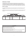
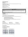
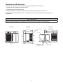
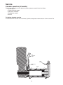
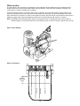
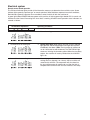
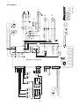
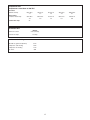
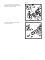
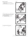
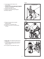
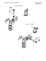
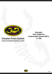
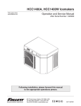
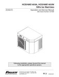
1
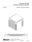
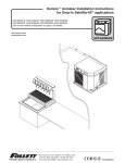
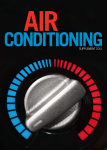
HCE1000A, HCE1000W 50Hz Icemakers
Order parts online
www.follettice.com
Operation and Service Manual
After Serial Number C20000
Following installation, please forward this manual
to the appropriate operations person.
801 Church Lane • Easton, PA 18040, USA
Toll free (800) 523-9361 • (610) 252-7301
Fax (610) 250-0696 • www.follettice.com
00171629R00
Follett Corporation
Equipment Return Policy
Follett equipment may be returned for credit under the following conditions:
1. The equipment is new and unused.
2. A return authorization number has been issued by customer service within 30 days after shipment.
3. Follett receives the equipment at the factory in Easton, PA within 30 days after issuance of the return authorization number.
4. The equipment must be returned in Follett packaging. If the packaging has been damaged or discarded, Follett will forward,
at the customer’s expense, new packaging.
Note:
Return freight charges are the responsibility of the customer. If equipment is returned and is damaged because of
improper packaging, Follett Corporation will not be held responsible.
Credit will be issued when:
The equipment has been inspected by Follett and deemed suitable to be returned to stock.
Note:
A 15% restocking charge will be deducted from the credit. If the cost to return the product to stock exceeds 15%, the
actual cost will be deducted.
2
Table of contents
Welcome to Follett Corporation
Specifications
Operation
Cleaning
Weekly exterior care
Monthly condenser cleaning
Semi-annual evaporator cleaning
Service
Icemaker operation
Water system
Electrical system
Normal control board operation
Test points
Time delay and self-flushing jumpers
Error faults
Hard error
Soft errors
Relay output indication
Compressor/refrigerant solenoid output
Wiring diagram
Compressor data
Gearmotor data
Resistance of windings
Mechanical system
Evaporator disassembly
Evaporator reassembly
Refrigeration system
Refrigeration pressure data
Refrigeration system diagram
Refrigerant charge size
Refrigerant replacement requirements
Evacuation
Ambients
Ice capacity test
Bin full detection system
Troubleshooting
Replacement parts
3
4
5
7
7
7
7
7
12
12
13
14
14
15
15
15
15
15
15
15
16
17
17
17
18
18
20
23
23
23
24
24
24
24
24
25
26
28
Welcome to Follett
Follett equipment enjoys a well-deserved reputation for excellent performance, long-term reliability and
outstanding after-the-sale support. To ensure that this equipment delivers the same degree of service, we ask
that you review the installation manual (provided as a separate document) before beginning to install the unit.
Our instructions are designed to help you achieve a trouble-free installation. Should you have any questions or
require technical help at any time, please call our technical service group at (800) 523-9361 or (610) 252-7301.
Before you begin
After uncrating and removing all packing material, inspect the equipment for concealed shipping damage. If damage
is found, notify the shipper immediately and contact Follett Corporation so that we can help in the filing of a claim,
if necessary.
Check your paperwork to determine which model you have. Follett model numbers are designed to provide information
about the type and capacity of Follett equipment. Following is an explanation of the different model numbers in the
1000 series.
Horizon Series Icemaker Model Number Configurations
HC
Icemaker
Voltage
HC Horizon
E 230/50/1
(self-contained only)
Chewblet®
E
1000
A
Series
1000 up to
1036 lbs
(471kg)
1400 up to
1450 lbs
(658kg)
B
T
Condenser
A Air-cooled, self-contained
W Water-cooled, self-contained
Application
Configuration
H Harmony™
B Ice storage
bin
S Satellite-fill™
T Top-mount
Chewblet is a registered trademark of Follett Corporation, registered in the US.
CAUTION
• Warranty does not cover exterior or outside installations
• Moving parts. Do not operate with front cover removed.
• Hot parts. Do not operate with cover removed.
• To reduce risk of shock, disconnect power before servicing
• Most ice machine cleaners contain citric or phosphoric acid, which can cause skin irritation. Read caution
label on product and follow instructions carefully.
• Ice is slippery. Maintain counters and floors around dispenser in a clean and ice-free condition.
• Ice is food. Follow recommended cleaning instructions to maintain cleanliness of delivered ice.
4
Specifications
Electrical
Each icemaker requires its own separate circuit with electrical disconnect within 10 ft (6m).
Equipment ground required.
Standard electrical – 220-240/50/1
Maximum icemaker fuse – 15 amps
Amperage – 11 amps
Maximum power – 3600 watts
Climatic class – N
6 ft (2m) cord provided on icemaker
CAUTION
• Plug must be provided by the end-user and must conform to standard EN 60 335-2-24:2003 of the end
destination
• If the supply cord is damaged, it must be replaced by the manufacturer or their service agent, or a similarly
qualified technician in order to avoid a hazard
Plumbing
3/8"
3/4"
1/4"
1/4"
OD push-in water inlet
MPT drain
FPT condenser inlet (water-cooled condenser only)
FPT condenser drain (water-cooled condenser only)
Notes: 3/4" vented drain line must slope a minimum of 1/4" per foot (6mm per 30.4cm run).
Drain to be hard piped and insulated.
To prevent back flow, do not connect drains.
Separate drains for icemaker and condenser.
Water shut-off recommended within 10 feet (3m).
Follett recommends installation of Follett model 00130286 activated carbon filter
in icemaker inlet water line.
Ambient
Air temperature
Water temperature
Water pressure – potable
Note:
100˚F/38˚C max.
90˚F/32˚C max.
70 psi max. (483 kPa)
50˚F/10˚C min.
45˚F/7˚C min.
10 psi min. (69 kPa)
Water-cooled condenser pressure 150 psi max (1034kPa); 10 psi min (69kPa)
Heat rejection
Air-cooled rejects 11,300 BTU/hr
Water-cooled rejects 12,800 BTU/hr
Ice production
Air-cooled icemaker capacity/24 hrs.
Water-cooled icemaker capacity/24 hrs.
F
C
50
10
60
16
70
21
80
27
90
32
60
16
1110
504
1054
478
1019
463
979
444
916
416
70
21
1017
462
948
430
887
403
875
397
787
357
80
27
890
404
822
373
770
350
715
325
656
298
90
32
761
346
738
335
715
325
671
305
600
273
Ambient Air Temperature F/C
100
38
731
332
665
302
624
283
577
262
521
237
lbs
kg
lbs
kg
lbs
kg
lbs
kg
lbs
kg
Inlet Water Temperature F/C
Inlet Water Temperature F/C
Ambient Air Temperature F/C
F
C
50
10
60
16
70
21
80
27
90
32
60
16
1004
456
965
438
919
417
837
380
781
355
70
21
969
440
919
417
879
399
813
369
773
351
80
27
908
412
852
387
817
371
764
347
746
339
90
32
818
371
766
348
734
333
684
311
676
307
100
38
695
316
663
301
630
286
567
258
534
243
lbs
kg
lbs
kg
lbs
kg
lbs
kg
lbs
kg
5
Dimensions and clearances
Entire front of icemaker must be clear of obstructions/connections to allow removal.
1" (26mm) clearance above icemaker for service.
1" (26mm) minimum clearance on sides.
The intake and exhaust air grilles must provide at least 150 sq in (968 sq cm) of open area.
Air-cooled model HCE1000A icemakers – 18" (458mm) minimum clearance between discharge and air
intake-grilles.
CAUTION
• Keep ventilation openings in the appliance enclosure or built-in structure, clear of obstruction
Front View
Side View
Back View
Ice transport hose connection
29.63" (753mm)
Air exhaust
both sides
21.28" (541mm)
Air exhaust
Cord only
23.50"
(597mm)
15.56"
(396mm)
PART NO
SERIAL NO
FULL LOAD AMPS
6.95"
(177mm)
2.53"
(65mm)
Easton Pennsylvania
CORPORATION
MODEL
VOLTS
HZ
SINGLE
PHASE
MOTOR COMPRESSOR THERMALLY PROTECTED
REFRIGERANT
DESIGN PRESSURE HIGH SIDE
CHARGE
OZ
LOW SIDE
PSIG
208264
Stock Module Identification Plate
Module No.
Product
MIN. BRANCH CIRCUIT AMPACITY
AMPS
MAX. BRANCH CIRCUIT FUSE SIZE
AMPS
UL
UL
R
R
NSF
MADE IN
THE USA
C
Service No.
2.43" (62mm)
21.05" (535mm)
23.77" (604mm)
Air intake
1/4" FPT condensor drain
(water-cooled only)
1/4" FPT condensor inlet
(water-cooled only)
6
3/8" OD push-in water inlet
3/4" MPT drain
Operation
Cleaning and preventive maintenance (all models)
Note:
Do not use bleach to sanitize or clean the icemaker.
Preventive maintenance
Periodic cleaning of Follett’s icemaker system is required to ensure peak performance and delivery of clean,
sanitary ice. The recommended cleaning procedures that follow should be performed at least as frequently as
recommended, and more often if environmental conditions dictate.
Cleaning of the condenser can usually be performed by facility personnel. Cleaning of the icemaker system,
in most cases, should be performed by your facility’s maintenance staff or a Follett authorized service agent.
Regardless of who performs the cleaning, it is the operator’s responsibility to see that this cleaning is performed
according to the schedule below. Service problems resulting from lack of preventive maintenance will not be
covered under the Follett warranty.
Weekly exterior care
The exterior may be cleaned with a stainless cleaner such as 3M Stainless Steel Cleaner & Polish or equivalent.
Monthly condenser cleaning (air-cooled icemaker only)
1. Use a vacuum cleaner or stiff brush to carefully clean condenser coils of air-cooled icemakers to ensure
optimal performance.
2. When reinstalling counter panels in front of remote icemakers, be sure that ventilation louvers line up with
condenser air duct.
Semi-annual evaporator cleaning (every 6 months)
WARNING
• Wear rubber gloves and safety goggles (and/or face shield) when handling ice machine cleaner or sanitizer
CAUTION
• Use only Follett approved SafeCLEAN™ Cleaner (part #00132001) and NU-CALGON IMS-II SANITIZER
• Do not mix Cleaner and Sanitizer solutions together
• DO NOT USE BLEACH
• It is a violation of Federal law to use these solutions in a manner inconsistent with their labeling
• Read and understand all labels printed on packaging before use
Note: Complete procedure for cleaning an sanitizing MUST be followed. Ice must be collected for
10 minutes before putting ice machine back into service.
Fig. 1
1. To clean – Remove cover. Press the CLEAN
button. The machine will drain. Wait for the LO
WATER light to come on (Fig. 1).
LO WATER
CL
EA
N
7
2. Mix 1 gallon (3.8L) 120˚F (49˚C) water and
7 ounces (198g) (one 7 ounce packet of Follett
SafeCLEAN ice machine cleaner, part# 00132001).
Locate cleaning cup. Fill until HI WATER light
comes on (Fig. 2).
Note: Do not use bleach to sanitize or clean the
icemaker.
Fig. 2
HI WATER
Fig. 3
3. Replace cover on cleaning cup. Wait until machine
restarts. Machine will clean, then flush 3 times in
approximately 12 minutes (Fig. 3).
12
Fig. 4
4. To sanitize – Press CLEAN button. The machine
will drain. Wait for LO WATER light to come on
(Fig. 4).
LO WATER
CL
EA
N
8
Fig. 5
5. Mix 1 gallon 120˚F (49˚C) water and 1.6 ounces
(48ml) NU-CALGON IMS-II SANITIZER. Fill until
HI WATER light comes on (Fig. 5).
Note: Do not use bleach to sanitize or clean the
icemaker.
HI WATER
6. Replace cover on cleaning cup. Wait until machine
restarts. Machine will sanitize, then flush 3 times in
approximately 12 minutes (Fig. 6).
Fig. 6
12
Fig. 7
7. To clean transport tube – Press power switch OFF
(Fig. 7).
9
8. Disconnect coupling as shown (Fig. 8).
Fig. 8
9. Using disposable food service grade gloves,
insert dry Sani-Sponge™ (kit part# 00132068).
Next, insert Sani-Sponge soaked in Nu-Calgon
IMS-II sanitizer solution. Push both Sani-Sponges
down ice transport tube with supplied pusher tube
(Fig. 9).
Fig. 9
(40 16"
7m
m)
1
2
3
Fig. 10
10. Remove and discard 16" (407mm) pusher tube
(Fig. 10).
10
Fig. 11
11. Reconnect coupling. Press power switch ON. Ice
pushes Sani-Sponges through tube (Fig. 11).
Fig. 12
12. Place a sanitary (2 gallon or larger) container in
bin or dispenser to collect Sani-Sponges and ice
for 10 minutes. Collect 5.5 lbs of ice from unit.
Discard ice and Sani-Sponges (Fig. 12).
11
Service
Icemaker operation (all models)
Follett’s icemaker consists of five distinct functional systems covered in detail as follows:
• Water system
• Electrical control system
• Mechanical assembly
• Refrigeration system
• Bin full
The Horizon icemaker overview
The Follett Horizon icemaker uses a horizontal, cylindrical evaporator to freeze water on its inner surface. The
ice
transport
tube
water
inlet
compression
nozzle
auger
12
Water system
The water level in the evaporator is controlled by a feed solenoid and level detecting sensors. Referencing the
diagram below, water sensing rods extend down into the reservoir at the end of the evaporator assembly. The
system works via electrical conductivity as follows:
One of the longest probes is a common. When water is between any of the other probes and the common, the
PC board will sense the activation. During normal operation, the water level rises and falls between the Normal
High and Normal Low sensors. As water is consumed to make ice, the level will fall until the Normal Low sensor is
exposed, triggering the water feed solenoid on. Water will fill until the Normal High sensor is activated.
Note: The potable water dissolved solids content must be greater than 10 mg/l for the water control system to
function properly. If using reverse osmosis water filtration system, ensure T.D.S level is greater than 10 mg/l.
Water system diagram
Water level diagram
13
Normal HI
Alarm LO
Common
Normal LO
Normal
operating
range
Electrical system
Normal control board operation
The PC board indicator lights provide all the information necessary to determine the machine's status. Green
indicator lights generally represent “go” or normal operation; Yellow indicators represent normal off conditions;
Red indicators generally represent alarm conditions, some of which will lock the machine off.
A green light labeled POWER indicates power to the machine. A flashing green light labeled CPU is normal and
indicates that the Central Processing Unit “heart beat” is working. All other normal operation status indicators are
covered as follows:
Ice machine disposition
Legend:
ON
OFF
ON or OFF
Operating conditions
FLASHING
1. Normal running.
POWER
LOW BIN
AUGER ON
REFRIG ON
TIME DELAY
CLEANING
PURGE
SERVICE
HI AMPS
HI PRESS
DRAIN CLOG
HI WATER
LO WATER
CPU
1. Ice machine is making ice.
POWER
LOW BIN
AUGER ON
REFRIG ON
TIME DELAY
CLEANING
PURGE
SERVICE
HI AMPS
HI PRESS
DRAIN CLOG
HI WATER
LO WATER
CPU
2. Ice machine is not making ice.
POWER
LOW BIN
AUGER ON
REFRIG ON
TIME DELAY
CLEANING
PURGE
SERVICE
HI AMPS
HI PRESS
DRAIN CLOG
HI WATER
LO WATER
CPU
3. Ice machine is not making ice.
2. Normal time delay. When the bin fills with ice, the LOW BIN
light goes out and the refrigeration and auger drive systems
immediately shut down. (Note: The fan motor will continue to
run for 10 minutes to cool condenser) The TIME DELAY light
comes on, initiating the time delay period. When the time delay
expires, the machine will restart provided that the LOW BIN
light is on.
3. Normal purge indicator. After a selected period of ice
making time has elapsed (1 or 2 hours), the ice machine will
automatically self-flush. The compressor will shut down but
the fan and gearmotor will continue to run. After the flush is
complete the machine will refill and start without a time delay.
14
Test points:
The Horizon PC board incorporates on-board test points that can be used to determine various electrical
outputs. The test point holes allow a standard probe to be inserted for quick voltage measurement. For 208-230
systems, use TP-4 (L2) as the common for testing outputs for solenoids, motors, etc.
Error faults:
The Horizon PC board monitors various operating parameters including high pressure, auger gearmotor
amperage limits, clogged drain, and high and low water alarm conditions. There are two types of errors namely
“hard” or “soft”. A hard error is one that shuts the machine off and will not allow restart until the reset button is
pressed. Even cycling power will not reset a hard error. A soft error can either be automatically reset should the
condition rectify, or if power is cycled. Should an error occur, consult the troubleshooting guide in this manual or
a Follett service technician. Note: there are two types of LO WATER and HI AMPS errors as listed below.
Soft errors:
HI AMPS: The PC board monitors the amperage of the auger motor. Should the gear motor experience current
draw above the 3.8 amps limit the machine will shut down and the TIME DELAY, HI AMP, and SERVICE LED’s
will be illuminated. After the time delay the machine will restart and the TIME DELAY, HI AMP, and SERVICE
LED’s will clear.
LO WATER: During operation, the water level cycles between the normal low and normal high sensors. Should
the water be shut off to a running machine, a soft error will occur. The error sequence is as follows: During
operation, the water level falls to the normal low sensor, and when it does the water feed solenoid is energized. If
water is not detected at the normal low sensor within 120 seconds, a soft error will occur. The machine will shut
down, but the water feed solenoid will remain energized. Should water return, it will fill to the normal low sensor
and the machine will resume normal operation. The error will clear automatically.
DRAIN CLOG: The drain clog sensor, located in the plastic drain pan behind the drain solenoid, will detect the
presence of water just below the top edge of the pan. If water does not properly flow out of the drain pan it will
rise to the sensor, especially during a self-flushing purge cycle.
Hard error:
HI AMPS:
1. “Two strikes” feature. If the gearmotor has a second HI AMP occurrence during the countdown period
(6 hours after a HI AMP time delay) a hard error will occur and the HI AMP and SERVICE LED’s will be
illuminated.
2. No current. To prevent the refrigeration system from running without gearmotor rotation the PC board will
indicate HIGH AMP and SERVICE if the drive relay is energized and there is no current draw.
HI PRESSURE: Should the refrigeration pressure rise above 425 psi, a hard error will occur. Even if pressure
fall-back below the reset point of 295 psi, the error will not clear and the machine will not restart.
LO WATER:
1. There is a sensor in the water reservoir that reaches down to the very bottom. The machine will not start if
water is not present at this sensor.
2. A hard error will occur should water not be present within 60 seconds of power up or if the sensors are
disconnected or damaged.
Relay output indication:
Each relay on the board has an indicator light associated with its output. For example, when the relay for the
water feed solenoid is energized, the adjacent indicator light glows green.
Comp/Sol output:
The output for the compressor is labeled COMP/SOL.
15
MOM
MAINT
S2
PURGE
BRN
+V
S3
CLEAN
(3 WIRE)
BLK
OUT (light on)
BLU
-V
OR
WATER LEVEL
(CONTACT CLOSURE)
INPUT 2
RETURN
1
2
3
J51
RED / GRAY PAIR
GRAY / GRAY PAIR
JUMPER
BIN
FULL
COM
4
8
DRAIN
CLOG
7
COM
6
NORM
HIGH
4
3
2
NORM
LOW
ALARM
LOW
LE
LE
1
1
1
J21
J22
J23
J24
RESET
SWITCH
CPU (G)
LE
LO WATER (R)
LE
DRAIN CLOG (R)
LE
J34
J33
J32
J31
LO PRESS (R)
J18
D15
D6
D5
C NO
K1
D9
C
SERVICE (R)
J2
FAN
DRV
J4
J5
J6
J7
J8
J9
J10
J11
J12
COMP
SOL
NO
L1
TP11
L2
TP4
K3
AMP
SENSING
D10
H2O H2O
DRN IN
TP8
PURGE (Y)
LE
HI WATER (R)
CONTROL PC BOARD
HI PRESS (R)
J17
CLEANING (Y)
1
HI AMPS (R)
TP7
TIME DELAY (Y)
J16
REFRIG ON (G)
J15
AUGER ON (G)
TP3
TP6
TP5
J13
J3
J14
LOW BIN (G)
16
POWER (G)
2
1
#12
BRN
#34
#9
#10
#11
RETURN
SIGNAL
BLU
#30
#31
#32
#19
K10
P
2
5
#16
2
OPENS @ EXCESS
HIGH PRESSURE
OPEN @ 425 PSI
CLOSE @ 295 PSI
GRN
GRN
HI
PRESS
6
BRN
1
#3
1
C1 RUN
#15
4
#28
.6 Amp Max
M2
1/2hp Max
M1
S
R
C
COMP
1ÿ/230Vac
>.50hp
P1
GND
L1
L2
00123232R10
801 CHURCH LANE
EASTON, PA 18040, USA
FOR SERVICE CALL:
800-523-9361 OR 610-252-7301
ON THE WEB: www.follettice.com
FAN
MOTOR
#27
#26
#25
P52 J52
K11
POTENTIAL
RELAY
208V/230Vac
BRN
2
3
#2
#1
J50
C2 START
#14
I
CONTACTOR
240Vac
20FLA
L1
O
2
5
FCV-2
50/60Hz
~11Amp DRAW RUNNING
ON/OFF SWITCH
240Vac / 20FLA
1
4
S1
DRAIN
20Watt
230Vac
BLU
PE
#13
#17
L2
#7
#8
WATER
INPUT
20Watt
230Vac
BLU
CB1
FCV-1
GRAY / GRAY PAIR
#18
SNUBBER
#33
Wiring diagram
Compressor data
Compressor current draw at 230 VAC
Air-cooled
Ambient air temp.
Water-cooled
Condenser water temp
60˚F/16˚C
7.1
70˚F/21˚C
7.5
80˚F/27˚C
7.8
90˚F/32˚C
7.8
100˚F/38˚C
8.1
50˚F/10˚C
7.0
60˚F/16˚C
7.0
70˚F/21˚C
7.4
80˚F/27˚C
6.7
90˚F/32˚C
8.0
Locked rotor amps
54
Gearmotor data
Gearmotor current
Brother
2.8A (nominal)
Locked rotor amps
15 amps
Resistance of windings
208-230 vac gearmotor (Brother)
6.2Ω
Compressor start winding
3.0Ω
Compressor run winding
1.4Ω
Fan motor
38Ω
17
Fig. 13
Mechanical system
Evaporator disassembly
1. Press PURGE button to purge evaporator, and then
turn power OFF.
2. Unscrew and remove stream divider as shown.
Fig. 14
3. Unplug and remove gearmotor as shown.
4. Remove all traces of petrol-gel from the auger shaft.
Fig. 15
5. Unscrew and disconnect transport tube from
louvered docking assembly.
6. Unplug sensor at the electrical box.
7. Remove vent tube from shuttle housing as shown.
18
Fig. 16
8. Loosen nut on V-band clamp and remove.
9. Remove V-band clamp from front of evaporator.
10. Remove main housing as shown.
Fig. 17
11. Remove and discard mating ring and seal.
12. Carefully remove auger.
19
Fig. 18
Evaporator reassembly
1. Remove and inspect O ring seal. Discard if
damaged in any way.
2. Clean O ring groove. Lubricate O ring and reinstall.
Fig. 19
3. Press new mating ring into main housing as shown.
4. Lube the shaft with liquid soap in the area shown
and slip on seal and spring.
Note: Do not touch the sealing surfaces. Use
cardboard disk to install.
Cardboard
disc
Lube
with soap
Do not
touch
Fig. 20
5. Reinstall main housing as shown.
20
Fig. 21
6. Orient auger shaft with keyway in the
upward position.
7. Force main housing into position against evaporator
and place 1/4" (7mm) diameter Phillips screwdriver
into hole in the auger shaft.
8. Replace V-band clamp as shown.
9. Replace nut on V-band clamp and tighten.
10. Remove screwdriver.
Note: Shuttle housing
removed for clarity
Fig. 22
11. Reconnect transport tube to louvered
docking assembly.
12. Plug sensor in at the electrical box.
13. Reconnect vent tube to the shuttle housing
as shown.
Fig. 23
14. Apply a light coat of petrol-gel compound to the
auger shaft.
15. Install gearmotor, making sure that insulation is
properly seated between gearmotor and main
housing as shown.
16. Firmly tighten four gearmotor bolts in place.
Apply
petrol-gel
21
Fig. 24
17. Insert a bolt into the auger shaft and finger tighten.
18. Using a wrench, rotate the shaft clockwise to align
the keyways in the gear housing and the shaft so as
to accept the key.
19. Insert the key into the keyway.
Fig. 25
20. Remove bolt and reinstall the washer and bolt.
Place retainer over bolt and secure with nut and
washer.
Fig. 26
21. Lubricate body of stream diverter with petrol-gel
and reinstall.
22. Plug gearmotor power cord into electrical box.
Apply
petrol-gel
22
Refrigeration system
Refrigerant pressure data
Air temperature
Air-cooled condensers
Pressure (psig)
discharge/suction
60˚F/16˚C
70˚F/21˚C
80˚F/27˚C
90˚F/32˚C
100˚F/38˚C
218/31
1503/213kPa
15.03/2.13bar
241/33
1661/234kPa
16.61/2.34bar
277/35
1909/241Kpa
19.58/2.41bar
313/38
2158/262kPa
21.58/2.62bar
349/41
2406/282kPa
24.06/2.82bar
Water temperature
Water-cooled condensers
Pressure (psig)
discharge/suction
Note:
60˚F/16˚C
70˚F/21˚C
80˚F/27˚C
90˚F/32˚C
100˚F/38˚C
279/33
1923/227kPa
18.96/2.27bar
225/33
1551/234kPa
15.51/2.34bar
231/33
1592/227kPa
15.92/2.27bar
232/34
1599/234kPa
15.99/2.34bar
236/40
1627/275kPa
16.27/2.75bar
The water control valve is factory set to maintain 275 ± 15 psi discharge pressure @ 70˚F water.
Refrigeration system diagram
high side
refrigeration
line run
high side
service port
low side
service port
filter
dryer
condenser
High pressure vapor
heat exchanger
low side
refrigeration
line run
High pressure liquid
thermostatic
expansion
valve
Low pressure liquid
compressor
Low pressure vapor
23
Refrigeration charge
All service on refrigeration systems must be performed in accordance with all federal, state and local laws. It is
the responsibility of the technician to ensure that these requirements are met. Recharging icemaker to other than
factory specifications will void the warranty.
R404A icemaker charge specifications
Model
Charge
Refrigerant type
HCE1000A (air-cooled)
24oz (652g)
R404A
HCE1000W (water-cooled)
15oz (426g)
R404A
Refrigerant replacement requirements
1. Non-contaminated refrigerant removed from any Follett refrigeration system can be recycled and returned
to the same system after completing repairs. Recycled refrigerant must be stored in a clean, approved
storage container. If additional refrigerant is required, virgin or reclaimed refrigerant that meets ARI
standard 700-88 must be used.
2. In the event of system contamination (for example, a compressor burn out, refrigerant leak, presence of
non-condensibles or moisture), the system must be repaired, evacuated and recharged using virgin or
reclaimed refrigerant that meets ARI standard 700-88.
3. Follett Corporation does not approve of recovered refrigerants. Improper refrigeration servicing procedures
will void the factory warranty.
Evacuation
Evacuate the system to a level of 500 microns. When the 500 micron level is reached, close all valves. Allow the
system to sit for approximately 20 minutes. During this period the system pressure should not rise. If the system
pressure rises and stabilizes there is moisture in the system and further evacuation is needed. If the pressure
continues to rise check the system for leaks.
Ambients
Air temperature1
Water temperature2
Minimum
50˚F/10˚C
45˚F/7˚C
Maximum
100˚F/37.8˚C
90˚F/32.2˚C
1Ambient air temperature is measured at the air-cooled condenser coil inlet.
2Ambient water temperature is measured in the icemaker water reservoir.
Ice capacity test
Icemaker production capacity can only be determined by weighing ice produced in a specific time period.
1.
2.
3.
4.
5.
6.
7.
8.
Replace all panels on icemaker.
Run icemaker for at least 15 minutes.
Weigh and record weight of container used to catch ice.
Catch ice for 15 or 20 minutes.
Weigh harvested ice and record total weight.
Subtract weight of container from total weight.
Convert fractions of pounds to decimal equivalents (ex. 6 lbs 8oz = 6.5 lbs).
Calculate production using following formula:
1440 min. x wt. of ice produced
=
Production capacity/24 hr. period
Total test time in minutes
9. Calculated amount per 24 hours should be checked against rated capacity for same ambient and water
temperatures in Ice Production Tables.
24
“Bin full” detection system
The Follett Horizon icemaker incorporates a unique “bin full” detection system that consists of the shuttle and
actuator. The shuttle incorporates a flag and sensor. Referencing the figure below, the normal running position
of the flag is down, out of the sensor. When the bin fills to the top and ice can no longer move through the tube,
the machine will force the shuttle flag up into the sensor, shutting the machine off. The shuttle actuator, located
above the ice bin allows the ice to curl up within it when the bin is full. In this way, there are no loads generated
that would tend to lift off the lid of the bin.
Shuttle flag and sensor
Running
Off
Shuttle actuator
Running
Off
25
Troubleshooting
Please see “Service” section for a description of each function.
Ice machine disposition
Legend:
ON
OFF
ON or OFF
Possible causes
FLASHING
POWER
LOW BIN
AUGER ON
REFRIG ON
TIME DELAY
CLEANING
PURGE
SERVICE
HI AMPS
HI PRESS
DRAIN CLOG
HI WATER
LO WATER
CPU
1. Ice machine is in running
condition but not making ice.
POWER
LOW BIN
AUGER ON
REFRIG ON
TIME DELAY
CLEANING
PURGE
SERVICE
HI AMPS
HI PRESS
DRAIN CLOG
HI WATER
LO WATER
CPU
3. Machine in TIME DELAY
without full bin.
POWER
LOW BIN
AUGER ON
REFRIG ON
TIME DELAY
CLEANING
PURGE
SERVICE
HI AMPS
HI PRESS
DRAIN CLOG
HI WATER
LO WATER
CPU
4. Ice machine is not making ice.
Locked in PURGE.
POWER
LOW BIN
AUGER ON
REFRIG ON
TIME DELAY
CLEANING
PURGE
SERVICE
HI AMPS
HI PRESS
DRAIN CLOG
HI WATER
5. Ice machine is not making ice.
HI AMPS.
LO WATER
1.
2.
3.
4.
5.
6.
Defective compressor.
Defective start relay.
Defective start capacitor.
Defective run capacitor.
Defective main contactor.
No output from PC board.
1.
2.
3.
4.
5.
6.
Replace
Replace
Replace
Replace
Replace
Replace
compressor.
start relay.
start capacitor.
run capacitor.
main contactor.
PC board.
1. Processor has been damaged.
1. Replace PC board.
1. Ice jamming due to improperly
installed transport tube causing a
false shuttle.
2. Shuttle stuck in up position.
3. Damaged or improperly installed
thermostat (open).
4. Transport tube backed-out of
coupling.
1. Correct transport tube routing.
1. A self-flush occurred but could
not drain evaporator due to a
failed drain solenoid valve.
2. A self-flush occurred but could
not drain evaporator due to water
reservoir or ice machine not
being level.
1. Replace drain solenoid valve.
1. Poor water quality causing ice to
jam auger.
2. Damaged shuttle mechanism or
thermostat (closed).
3. Kinked transport tube
(thermostat systems).
4. Intermittent drive output from
PC board. Evaporator will freeze
causing a hi amps error.
5. Gearmotor is unplugged.
1. Clean ice machine. Increase
flushing frequency.
2. Replace or repair shuttle mechanism/
thermostat.
3. Straighten transport tube.
POWER
LOW BIN
AUGER ON
REFRIG ON
TIME DELAY
CLEANING
PURGE
SERVICE
HI AMPS
HI PRESS
DRAIN CLOG
HI WATER
LO WATER
CPU
2. The CPU is not flashing.
CPU
Corrective actions
2. Repair or replace shuttle mechanism.
3. Replace or reposition thermostat.
4. Correct coupling installation.
2. Level ice machine. Check water
reservoir to make sure it is not tilted
towards the compressor.
4. Replace PC board.
5. Plug in gearmotor.
(see page 15 for “no current” details)
POWER
LOW BIN
AUGER ON
REFRIG ON
TIME DELAY
CLEANING
PURGE
SERVICE
HI AMPS
HI PRESS
DRAIN CLOG
HI WATER
LO WATER
CPU
6. Ice machine is not making ice.
HI PRESSURE.
1. High ambient temperatures
>100˚F (38˚C).
2. Poor ventilation or air
recirculation.
3. Clogged condenser.
4. Fan not working properly. No
air flow.
• Blocked fan blades
• No fan output from PC board
• Faulty fan motor
26
1. Air condition area to below 100˚F
(38˚C).
2. Reposition ice machine or properly
ventilate. Prevent ice machine exhaust
from recirculating.
3. Clean condenser grille.
4. Correct air flow.
• Remove any blockage from fan blades
• Replace PC board
• Replace fan motor
Ice machine disposition
Legend:
ON
OFF
ON or OFF
POWER
LOW BIN
AUGER ON
REFRIG ON
TIME DELAY
CLEANING
PURGE
SERVICE
HI AMPS
HI PRESS
HI WATER
LO WATER
CPU
DRAIN CLOG
POWER
LOW BIN
AUGER ON
REFRIG ON
TIME DELAY
CLEANING
PURGE
SERVICE
HI AMPS
HI PRESS
DRAIN CLOG
HI WATER
LO WATER
CPU
8. Ice machine is making ice.
Excessive water in bin or
coming into bin from transport
tube.
POWER
LOW BIN
AUGER ON
REFRIG ON
TIME DELAY
CLEANING
PURGE
SERVICE
HI AMPS
HI PRESS
DRAIN CLOG
HI WATER
9. Ice machine is not making ice.
Lo water.
LO WATER
Corrective actions
1. Drain hose kinked or plugged
causing water to back up.
2. Improper floor drain routing/pitch
causing water to back up.
3. High TDS levels and leaking
drain solenoid may cause an
errant drain clog.
1. Remove kink or blockage from
drain hose.
2. Re-route floor drain.
1. Failed water sensors. Processor
assumes there is no water when
there is water.
2. Blocked reservoir vent.
3. Defective water feed solenoid
valve. Stuck in open position.
1. Clean or replace water probe
assembly. Check wiring
connections.
2. Clean or replace vent tubes.
3. Replace water feed solenoid
valve.
1. Water supply is turned off.
1. Turn water supply on. If evaporator
was completely empty the reset
button may have to be pressed to
restart the ice machine.
2. Ice machine will eventually start
when water reaches normal lo level.
3. Replace water feed solenoid valve.
FLASHING
7. Ice machine is not making ice.
Drain clog.
CPU
Possible causes
2. Low water pressure.
3. Defective water feed solenoid
valve. Stuck in closed position.
4. No water feed output from
PC board.
27
3. Clean area around drain sensor
and/or replace
Drain solenoid valve.
4. Replace PC board.
Order parts online
www.follettice.com
Replacement parts
Evaporator assembly
2
3
20
5
1
7
4
21
22
6
23
19
17
18
16
15
27
14
9
10
24
26
8
23
28
24
32
13
12
23
25
30
11
24
31
23
29
18
35
34
18 17
33
40
41
38
23
37
28
28
39
36
Order parts online
www.follettice.com
Reference #
1
2
3
4
5
6
7
8
9
10
11
12
13
14
15
16
17
18
19
20
21
22
23
24
25
26
27
28
29
30
31
32
33
34
35
36
37
38
39
40
41
Not shown
Description
Tube, ice transport, molded
Shuttle assembly (includes 00115600 & 0013066)
Switch, optical
Compression nozzle
Elbow, water
Gasket, shuttle
Stream divider
Auger bolt
Washer
Retainer, auger bolt
Kit, auger bolt (auger bolt, washer, retainer, nut and washer)
Key
Bolts, gearmotor mounting (4)
Gearmotor, 240V (includes capacitor)
Gasket, gearmotor
Main housing (includes 00112946 & 00116962)
Coupling, V-band
O ring
Seal, auger shaft
Cup, sanitizer
Gasket, sanitizer
Cap, sanitizer (includes 00124032)
Tubing, water, 3/8" OD
Tubing, water, 1/4" OD
Hardware, mounting, evaporator cap
Solenoid, water feed (240V)
Tee, water
Sensor assembly, water level and drain clog
Cap, evaporator (includes 00125468 & 00130989)
Clip, water shut-off valve
Strainer, water
Valve, shut-off, water
Auger (includes 00112946 & 00116962)
Evaporator (includes 00112946, (2) 00116962 & 0012116)
Journal housing and bearing (includes (2) 00116962)
Reservoir, water
Base, evaporator
Boot, solenoid
Solenoid, purge (240V)
Insulation, evaporator
Spacers, solenoid
Insulation, evaporator cap
29
Part #
00130666
00130815
00130849
00115774
00134502
00115600
00142513
00116988
00161513
00161366
00161406
00117804
00130641
00130807
00121632
00142539
00130708
00116962
00112946
00130674
00124032
00130880
502719
502079
00130989
00130831
00134494
00171363
00130740
502922
502920
502921
00147249
00130724
00130716
00130690
00130732
00160309
00130765
00121616
00160317
00125468
Air-cooled assembly
Order parts online
www.follettice.com
1
2
3
4
5
7
9
13
8
14
15
10
6
11
12
30
Order parts online
www.follettice.com
Reference #
1
2
3
4
5
6
7
8
9
10
11
12
13
14
15
Description
Condenser (includes 00130922)
Shroud, condenser
Fan motor assembly
Electrical box support
Cut-out, high pressure safety
Insulation, bulb, TXV
Drier
Valve, expansion, thermal (includes 502830 and 00106534)
Insulation, TXV
Hardware, evaporator mounting base (set of four)
Compressor
Base, icemaker
Heat exchanger (includes 00172361)
Heat exchanger insulation
Fan blade
31
Part #
00130914
00130922
00130930
00156035
00117077
00106534
502724
00130997
502830
00130971
00121582
00130856
00172353
00172361
00170290
Water-cooled assembly
Order parts online
www.follettice.com
1
3
2
7
4
20
9
5
19
6
11
12
8
13
10
15
16
11
15
17
14
12
18
32
13
Order parts online
www.follettice.com
Reference #
1
2
3
4
5
6
7
8
9
10
11
12
13
14
15
16
17
18
19
20
Description
Electrical box support
Elbow, water
Valve, water regulating
Union, water
Cut-out, high pressure safety
Insulation, bulb, TXV
Drier
Valve, expansion, thermal (includes 502830 and 00106534)
Insulation, TXV
Condenser, w/c
Elbow, water, 90˚
Valve, shut-off, water
Coupling
Hardware, evaporator mounting base
Ty-rap
Receiver
Compressor
Base, icemaker
Heat exchanger (includes 00172361)
Heat exchanger insulation
33
Part #
00156035
00129486
00131052
202148
00117077
00106534
502724
00130997
502830
00117234
00129478
502222
206411
00130971
204584
00123109
00121582
00130856
00172353
00172361
Electrical box
Order parts online
www.follettice.com
1
2
6
3
7
5
4
8
9
10
15
11
12
13
14
34
Order parts online
www.follettice.com
Reference #
1
2
3
4
5
6
7
8
9
10
11
12
13
14
15
Description
Cover, electrical box, air/water-cooled
Board, control circuit, 240V (includes 00130906)
Stand off’s (set of 6)
Capacitor, compressor run
Clamp, run capacitor
Relay, compressor starting
Contactor
Capacitor, compressor starting
Cap, capacitor
Bracket, capacitor
Switch, evaporator purge
Switch, evaporator clean
Switch, icemaker power
Circuit breaker, 4 amp
Power lead, 240V
35
Part #
00130872
00132902
00130906
00121814
00117044
00141648
00117010
00141663
00123216
207625
00114371
00117036
208867
00126912
00163923
Integration kit – top-mount and Satellite-fill
Order parts online
www.follettice.com
Top mount configuration
1
2
10
13
2
12
11
4
5
Satellite-fill configuration
6
1
7
8
11
12
10
2
4
5
6
7
8
36
2
9
Order parts online
www.follettice.com
Reference #
1
2
3
4
5
6
7
8
9
9
10
11
12
13
Not shown
Not shown
Not shown
Not shown
Not shown
Not shown
Description
Shuttle actuator
Clamp
Actuator elbow (includes 00167122 and 209100)
Screws
Gasket
Actuator body
Gasket, coupling
Ring, locking (includes 00126532)
Ice transport tube, 10' (3m)
Ice transport tube, 20' (6m)
Insulation, transport tube
Insulation, elbow
Insulation, actuator
Ice transport tube, top mount, 30" (762mm)
Integration kit, top mount
Integration kit, Satellite-fill (requires transport tube)
Extension-fill tube, 9"
Extension-fill tube, 4"
Follett SafeCLEAN ice machine cleaner (case of 24 x 7oz packets)
Sani-spong kit
37
Part #
00171322
500377
00171264
209100
00167122
00171272
00126532
00171371
00171280
00171298
501176
00168922
00168930
00171306
00171389
00171397
00135723
00153684
00132001
00132068
Skins assembly
Order parts online
www.follettice.com
2
1
6
3
7
5
15
4
lvan
nsy
Pen
on
T NO
East
PAR
HZ
N
NO
ATIO IAL
SER
POR
RGE
TED
COR
TS
TEC
CHA
VOL
PRO
E
SID
LLY
RMA
LOW
R THE
SSO
PS
PRE
R
D AM
COM
TOR
C
MO
R
S
E
AMP
NT
H SID
ERA
S
RIG
HIG
AMP
RE
REF
SSU
DEL
MO
ia
GLE
SIN SE
PHA
13
OZ
PSIG
E IN
MADUSA
THE
NSF
UL
FUL
L LOA
UL
Y
ACIT
AMP
IGN
UIT
DES
SIZE
CIRC
CH
FUSE
UIT
BRAN
CIRC
MIN.
CH
. BRAN
MAX
PRE
208264
Stock Module Identification Plate
Module No.
Product
Service No.
17
16
11
12
8
9
10
14
38
Order parts online
www.follettice.com
Reference #
1
2
3
4
5
6
7
8
9
10
11
12
13
14
15
16
17
Not shown
Not Shown
Description
Grille, intake
Front cover, air- & water-cooled (includes 00122846)
Tubing, water, 1/4" OD
Tubing, drain
Fitting, drain
Fitting, water inlet
Elbow, water inlet
Coupling (includes 00144675)
O ring
Bulkhead fitting
Nut
Hose clamp
Power cord, 240V
Louvered docking assembly (includes 0123182)
Clamp, drain line
Screws
Bulkhead connector kit
Gasket, intake
Louver, intake/exhaust (13.75"x17.75")
39
Part #
00122846
00130625
502079
00144923
00109728
502924
502925
00171207
00144675
00171215
00145342
500377
00134445
00130658
00114520
208568
0017223
00135574
00128066
801 Church Lane • Easton, PA 18040, USA
Toll free (800) 523-9361 • (610) 252-7301
Fax (610) 250-0696 • www.follettice.com
00171629R00
05/07