1
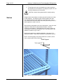
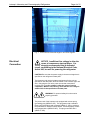
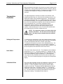
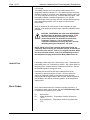
Instruction Manual
Fisher Scientific Isotempâ
Chromatography and General Purpose Laboratory
Refrigerators
Chromatography Refrigerator Models
13-986-127G/GR/GA
13-986-127GHK
13-986-133G/GR/GA
13-986-133GHK
13-986-138G/GR/GA
13-986-138GHK
13-986-145G/GR/GA
13-986-145GHK
13-986-149G/GR/GA
13-986-149GHK
13-986-172G/GR/GA
13-986-172GHK
General Purpose
Laboratory Refrigerator Models
13-986-227R/G/RR/RA/GR/GA
13-986-227GHK
13-986-238G/GR/GA
13-986-238GHK
13-986-245G/GR/GA
13-986-245GHK
13-986-249R/G/RR/RA/GR/GA
13-986-249GHK
13-986-272G/GR/GA
13-986-272GHK
Service Division (Repairs): 1-800-395-5442
Technical Support: 1-800-926-0505
Customer Service: 1-800-766-7000
Prior to calling for service, have the following information readily available:
Catalog Number:
Serial Number:
Date of Purchase:
The catalog number and serial number can be found on the data plate located on the left interior
wall of the unit.
Part Number: 104416
Table of Contents
Isotemp Chromatography/ Laboratory Refrigerators
Introduction.................................................................................................................................... 1
Unpacking ...................................................................................................................................... 1
Visible Loss or Damage............................................................................................................. 1
Concealed Loss or Damage ..................................................................................................... 1
Packing List ................................................................................................................................. 1
Installation...................................................................................................................................... 2
Selecting a Location................................................................................................................... 2
Leveling the Unit ......................................................................................................................... 2
Door Handles .............................................................................................................................. 2
Door Removal and Adjustment ................................................................................................ 2
Shelves......................................................................................................................................... 3
Electrical Connection ................................................................................................................. 4
Operation ........................................................................................................................................ 5
Control Layout............................................................................................................................. 5
Temperature Controller.............................................................................................................. 6
Setting the Temperature ....................................................................................................................................6
Units Select ............................................................................................................................................................6
Calibration Offset ................................................................................................................................................6
Hold-Off Time ......................................................................................................................................................7
Error Codes ................................................................................................................................. 7
Fluorescent Lamps..................................................................................................................... 8
Convenience Outlet.................................................................................................................... 8
Manual/Automatic Condenser Fan .......................................................................................... 8
Trouble Shooting Table .............................................................................................................. 9
Maintenance................................................................................................................................. 10
Cabinet Cleaning ...................................................................................................................... 10
Cleaning the Condenser.......................................................................................................... 10
Condensate Evaporator Pan .................................................................................................. 10
Replacement Parts..................................................................................................................... 11
Performance Characteristics .................................................................................................. 11
Power Requirements ................................................................................................................. 11
Wiring Diagram ........................................................................................................................... 12
Part Number: 104416
Page 1 of 12
Introduction
Isotempâ Laboratory and Chromatography Refrigerators
Your satisfaction and safety are important to Fisher Scientific, a
complete understanding of this unit is necessary to attain these
objectives.
As the ultimate user of this apparatus, it is your responsibility to
understand its proper function and operational characteristics. This
instruction manual should be thoroughly read and all operators given
adequate training before attempting to place this unit in service.
Awareness of the stated cautions and warnings, and compliance with
recommended operating parameters – together with maintenance
requirements – are important for safe and satisfactory operation. The
unit should be used for its intended application; alterations or
modifications will void the Warranty.
WARNING: As a routine laboratory precaution, always
wear safety glasses when working with this apparatus.
Unpacking
This product is not intended, nor can it be used, as a sterile or
patient connected device. In addition, this apparatus is not
designed for use in Class I, II or III locations as defined by the
National Electrical Code, unless otherwise noted.
Save all packing material if apparatus is received damaged. This
merchandise was carefully packed and thoroughly inspected before
leaving our factory.
Responsibility for its safe delivery was assumed by the carrier
upon acceptance of the shipment; therefore, claims for loss or
damage sustained in transit must be made upon the carrier by
the recipient as follows:
Visible Loss or
Damage
Concealed Loss or
Damage
Note any external evidence of loss or damage on the freight bill, or
express receipt, and have it signed by the carrier’s agent. Failure to
adequately describe such external evidence of loss or damage may
result in the carrier’s refusing to honor your damage claim. The form
required to file such a claim will be supplied by the carrier.
Concealed loss or damage refers to loss or damage, which does not
become apparent until the merchandise has been unpacked and
inspected. Should either occur, make a written request to the
carrier’s agent within 15 days of the delivery date; then file a claim
with the carrier since the damage is the carrier’s responsibility.
If you follow the above instructions carefully, we will guarantee our full
support of your claim to be compensated for loss from concealed
damage.
DO NOT – FOR ANY REASON – RETURN THIS UNIT WITHOUT
FIRST OBTAINING AUTHORIZATION
Packing List
Part Number: 104416
The following items are packed in the envelope located inside the
refrigerator chamber. If any of the following items are not present,
report the missing item to your local Fisher representative.
1. Warranty Card
5. Chart Recorder Instructions
2. This Instruction Manual
3. Door Lock Key
4. Power Switch Key
Isotempâ Laboratory and Chromatography Refrigerators
Installation
Selecting a Location
Leveling the Unit
Choose a location for the refrigerator that will provide at least three
inches of clearance between the cabinet and any adjacent vertical
surface at the sides and rear. Appropriate electrical power must be
available. Locate the refrigerator within 6 feet of the power outlet so
that no extension cord is required.
The refrigerator must be level in order to provide adequate
condensation drainage as well as proper door alignment and
operation. The refrigerator should be in its final operating location and
set so that it is firmly positioned on the floor. There are four leveling
screws, one on each corner. . Level the cabinet front to rear and sideto-side using the corner leveling screws. The leveling screws are
accessed by removing the base grille, as described below:
1.
2.
3.
4.
Door Handles
Door Removal and
Adjustment
Page 2 of 12
Remove the lower grille attaching screws.
Grasp the grille with both hands.
Tilt the lower end of the base grille toward you.
Pull grille away from the refrigerator
(Swinging Door Models Only)
Door handles are packed inside each refrigerator. To mount the
handle, lift the door gasket behind the two screws on the front of the
door. Attach handle with offset away from the cabinet corner and
tighten the screws.
(Sliding Door Models Only)
Each door has its own closing spring located at the top of the door
track. Each spring is set for proper tension. If adjustment is required:
1. Check for cabinet level (see above).
2. Remove the door(s) by lifting it and sliding about half way
open. The roller will fall into a gap in the upper track. While
maintaining upward pressure on the door, pull the bottom
outward until it clears the bottom track.
3. Adjust the location of the door rollers in the roller brackets
(above door) as shown by loosening the lock nut on the back
of the roller bracket and moving the roller up or down.
Closing spring
Lock nut on back
Roller
Fig. 1
Part Number: 104416
Isotempâ Laboratory and Chromatography Refrigerators
Page 3 of 12
4. The spring tension can be adjusted by moving the spring to
the outside hole of the bracket or by snipping a portion of it off
and then refastening it to the bracket.
CAUTION: Where safety glasses before snipping spring.
Shelves
Shipped inside each cabinet are shelves packed in plastic and a bag
of shelf supports. Two different types of shelf supports are used.
The shelf supports have tab lengths of ¼ inch and ½ inch. The ¼
inch versions are used in the front of the shelf (See below) and the ½”
shelf supports are used in the rear.
Shelf spacing is adjustable to suit user requirements. Insert four shelf
supports for each shelf into the pilasters as shown. Note the
numbers on the pilasters. Place supports on the same numbers on
each pilaster to ensure the shelf will be level. Place the shelf on the
pilasters as shown in Fig’s 2 and 3.
Replacement shelves are available individually. See page 11 for
shelf part numbers. Proper shelf orientation is illustrated in Figure 2.
NOTE: Chromatography units include additional ½ shelves, which
can be used in place of the full shelves.
Shelf Support
Tab Length
Fig. 2
Part Number: 104416
Use ¼” tab length supports on sides and ½’ in back.
Isotempâ Laboratory and Chromatography Refrigerators
Fig. 3
Electrical
Connection
Page 4 of 12
Place shelves at desired height on four shelf supports.
NOTICE: Insufficient line voltage is often the
cause of compressor start-up failure. It is
strongly recommended that a dedicated
circuit, conforming to the National Electrical Code,
Article 440, be used for powering the refrigerator.
CAUTION: Be sure that the power supply is the same voltage that is
specified on the refrigerator’s data plate.
The frequency and nominal voltage requirements for the unit are
specified on the data plate, which is located on the interiors upper left
side. Only plug the unit into a power source that meets these
requirements. Low line voltage is often the cause of service
complaints. With the unit running, check that the line voltage is
within ±10% of that specified on the data plate.
WARNING: For personal safety this unit must be
properly grounded.
The power cord of this instrument is equipped with a three prong
(grounding) plug (NEMA 5-15P). This plug mates with a standard
three prong (grounding) wall receptacle (NEMA 5-15R) to minimize
the potential of an electrical shock hazard. Chromatography models
are equipped with a (NEMA 5-20P). This plug must mate with a
(NEMA 5-20R).
Part Number: 104416
Page 5 of 12
Isotempâ Laboratory and Chromatography Refrigerators
The customer should have the wall receptacle and circuit checked by
a qualified electrician to verify the receptacle is properly grounded
and meets power requirements specified on the data plate.
WARNING: DO NOT under any circumstances cut or
remove the third (ground) prong from the power cord. DO
NOT use a two-prong adapter plug.
Where a two prong wall receptacle is encountered, it is the personal
responsibility and obligation of the user to have it replaced with a
properly grounded three prong receptacle.
CAUTION: Do not use an extension cord. Use of an
ungrounded cord or an overloaded circuit VOIDS the
compressor warranty.
Operation
WARNING: If the unit is tilted in excess of 30 degrees, level
the unit then wait at least 12 hours before applying power to
it.
WARNING: This product is not approved for storage
of flammable or explosive materials. Also, it is not
approved for use in hazardous locations containing
explosive atmospheres.
Control Layout
Part Number: 104416
Before operation, become familiar with the refrigerator controls
located on the refrigerator header panel. A layout of the control is
given below.
Isotempâ Laboratory and Chromatography Refrigerators
Page 6 of 12
Begin operation by inserting the key into the key switch located on the
header panel. The key switch is packed inside the envelope, which is
shipped in the refrigerator chamber. Turning the key switch to the ON
( | ) position will energize the evaporator fans and the digital
controller.
Temperature
Controller
The digital temperature controller is located on the left side of the
header panel (See Figure 4). When the unit is initially turned on, the
display will indicate current chamber temperature. The temperature
units will be indicated by the °C or °F LED located just to the right of
the temperature display. The refrigerator is factory set at 4°C. When
the unit is first energized the evaporator fans will operate however it
will not immediately cool. A 3-minute compressor delay is
programmed into the controller to provide sufficient time for the
evaporator to defrost and to allow the system pressure time to
equalize. When the delay time is over, the Cool LED will illuminate,
the compressor will run and the chamber will cool.
NOTE: The compressor requires a 3-minute delay time
between activations. The unit will not cool during this
delay. The delay is also activated when the controller
is first energized.
Setting the Temperature
Units Select
Calibration Offset
Part Number: 104416
To change the set temperature, press and release the Menu keypad
once. The display will flash SP and the Mode LED will be illuminated.
The last set temperature will then be shown in the display.
To change the temperature, press the UP or DOWN arrow key. The
adjustable temperature range is 1 to 12°C (34 to 54°F). When the
desired set temperature is displayed, press the Menu keypad to enter
the set temperature and activate the Units Select menu.
The second menu selects the units. The refrigerator control displays
temperature in °C or °F. The factory setting is °C. Starting from the
temperature display mode (Mode LED off), press the Menu key twice.
The current temperature units are displayed. To switch between
units, press the UP or DOWN arrow key then press the Menu key to
select. The unit LED will be displayed on the right of the temperature
display.
In the event the refrigerator needs to be calibrated, a simple routine is
available to adjust the display and control point to a referenced
standard. To set a temperature offset, press and hold the Menu
keypad for 5 seconds. The display will flash oS followed by the last
temperature offset value. The factory setting is 0. To change the
offset value, press the UP or DOWN arrow key, then press the Menu
key. The value shown in the display will be added to the previous
temperature reading. The display will then flash Ho.
Isotempâ Laboratory and Chromatography Refrigerators
Page 7 of 12
For Example:
The display indicates 4°C but a reference thermometer in the
refrigerator chamber indicates 6°C. The operator presses and holds
the Menu keypad for 5 seconds, then changes the display value from
0 to +2 by using the UP arrow key. Press the Menu key again. Now
the display indicates a chamber temperature of °6 C and the
controller begins to cool (as long as 3-min. delay period has expired)
to the desired temperature of 4°C as shown on the reference
thermometer.
Allow an additional 30 to 40 minutes for the refrigerator to again
stabilize. If the display is still inaccurate, repeat the calibration offset
procedure.
CAUTION: INCREASING the offset value DECREASES
the temperature at which the system controls. If the
offset is inadvertently set too high, the chamber’s
control temperature can fall below zero and cause
evaporator freeze-up. This is caused by the
evaporator temperature not rising above 0°C and not
defrosting during the compressor “off cycle”.
NOTE: While in any of the controller mode setups (temp set,
calibration offset or units), the controller will wait 15 seconds for
a new value to be entered. If there is no keypad operation within
the 15-second time window, control will automatically revert to
the temperature display mode and the Mode LED will turn off.
Hold-Off Time
Following the offset menu is the hold-off (Ho) menu. The display will
momentarily flash “Ho”, followed by a number. The number shown is
the delay time in minutes between compressor activations. Use the
UP/DOWN keypads to change the value.
Increasing the hold-off time will allow additional time for the
evaporator to defrost during the off-cycle. This can reduce the
chance of evaporator freeze-up during times of high humidity.
Pressing the Menu keypad while in the Ho mode, enters the hold-off
time displayed, and returns controller operation to the temperature
display mode.
Error Codes
Error codes indicate when the controller is sensing a problem. A
description of each is given below. See the Troubleshooting Table
for additional information on error codes.
E1
E2
E3
Part Number: 104416
Open sensor.
Under temperature. Temperature at sensor is less than
–36°C.
Over temperature. Temperature at sensor is greater than
37°C.
Isotempâ Laboratory and Chromatography Refrigerators
Page 8 of 12
Fluorescent Lamps
The interior lamp is controlled by a rocker switch on the header panel.
This light may be operated any time the cabinet power is turned on at
the keyed power switch. If the interior lamp fails, replace with the
same size and wattage lamp. DO NOT USE REDUCED WATTAGE
LAMPS. The reduced wattage lamps generally fail to light below 60
°F (15 °C).
Convenience Outlet
Chromatography Refrigerators come equipped with a convenience
outlet located in the center of the back wall. Model 172G’s (three
doors) have two convenience outlets. The total power that can be
supplied by the outlet (or outlets in 3-door models) is 5A @ 120VAC
(4A @ 120VAC for the 3-door models). The outlet(s) is protected by
a circuit breaker located just below and to the right of the outlet(s).
Pressing the breaker button resets the breaker after a fault.
(Chromatography
Refrigerators Only)
WARNING: The convenience outlet is LIVE at any time the
unit is connected to an electrical power source, regardless
of the position of the key switch.
Manual/Automatic
Condenser Fan
A rocker switch located on the left side of the top of the inside of the
chamber is used to operate the condenser fan automatically or
manually. With the switch in the automatic position, the condenser
fan operates with the compressor. In the manual position, the
condenser fan operates continuously.
During times of high ambient relative humidity conditions, more water
is condensed on the evaporator and directed to the condensate pan.
The condenser fan will run continuously in the manual setting to
better dispose of this water. At times of low relative humidity, the
switch can be set to automatic.
Part Number: 104416
Isotempâ Laboratory and Chromatography Refrigerators
Page 9 of 12
Trouble Shooting
Table
This table is intended to assist in resolving user-correctable
Refrigerator problems by relating symptoms to their likely causes. If
service beyond the scope of this table is required, contact Fisher
Scientific Service Division @ 1-800-395-5442.
Symptom
Does Not Run
Action
Plug in Unit
Blown fuse or tripped circuit
breaker.
Check fuse or circuit
breaker at breaker
box.
Defrost unit. Increase
Ho time.
Runs
Continuously
Frost buildup on refrigeration
coils
Clicking
Sound
The compressor is equipped
with a thermal protector. This
device shuts off the
compressor when it becomes
to hot. A clicking sound
occurring about every 30
seconds indicates this
protector is working
Set temp is to high
Disconnect power and
call for service.
Condenser coil dirty
Clean condenser coil
with a vacuum cleaner
Unit frosted
Open sensor
Defrost unit
Check sensor
connection
Under Temp
Temperature at sensor
is less than –36°C or
sensor is
malfunctioning.
Temperature at sensor
is greater than 37°C or
sensor is
malfunctioning
Insufficient
Cooling
Display shows
E1 (error
code)
Display shows
E2 (error
code)
Display shows
E3 (error
code)
Part Number: 104416
Probable Cause
Unit Unplugged
Over Temp
Reduce temperature
setting, verify Cool
LED is on.
Isotempâ Laboratory and Chromatography Refrigerators
Maintenance
Cabinet Cleaning
Page 10 of 12
CAUTION: When servicing the unit, disconnect from
the electrical power source
The cabinet interior should be cleaned frequently. Any spilled liquid
should be wiped off immediately. Stains resulting from some spills
can be permanent if not quickly removed. The most convenient time
to clean the interior is after defrosting. The cabinet exterior should be
cleaned occasionally. A mild detergent and lukewarm water or a
solution of bicarbonate of soda (1 tablespoon per gallon of water) is
recommended for cleaning the interior and exterior of the cabinet. All
surfaces should be rinsed and thoroughly dried.
CAUTION: Do not use any type of abrasive such as steel
wool, or fluids such as gasoline, Naphtha, or thinner. These
materials could be harmful to plastic materials, door gasket,
and painted surfaces.
Cleaning the
Condenser
For efficient operation, it is recommended that the condenser coil and
fan be cleaned every 4 to 6 months.. The condenser coil is located
behind the base grille, at the bottom of the unit.. See Leveling the
Unit for instructions on removing the base grille.
Vacuum clean the front surface of the coil thoroughly, or direct forced
air through the condenser from the rear. If necessary, use a stiff
bristled brush to loosen any dirt. Failure to keep the condenser clean
will void the warranty.
Caution: Accessing and cleaning the condenser coil or
evaporator pan should be done by qualified personnel.
Condensate
Evaporator Pan
Part Number: 104416
The condensate evaporator pan is located behind the base grill
between the condenser fan and compressor. This pan should be
cleaned at least once a year to prevent foul odors and operate
efficiently. Vacuum clean if dry, or sponge clean with soapy water.
Isotempâ Laboratory and Chromatography Refrigerators
Page 11 of 12
Replacement
Parts
Replacements for Laboratory Refrigerator parts serviceable by the
user may be ordered, by part number, from Fisher Scientific Co. @
1-800-766-7000.
Item
Part Number
Shelves
Model 127/227
Model 133/233
Model 138/238
Model 145/245
Model 149/249 & 172/272
½ Shelves
Model 127/227
Model 133/233
Model 138/238
Model 145/245
Model 149/249 & 172/272
13-986-210A
13-986-210B
13-986-210U
13-986-210C
13-986-210D
13-986-210F
13-986-210G
13-986-210T
13-986-210H
13-986-210J
Solid State Relay (K1)
Temperature Controller
International Version Controller (220V)
Condenser Pan Wick
Front Shelf Support
Rear Shelf Support
Performance
Characteristics
Power
Requirements
Temperature Range: 1° to 12°C (34° to 54°F)
Temperature Stability: +/- 3°C
Catalog Number
13-986-127G/GR/GA
13-986-133G/GR/GA
13-986-138G/GR/GA
13-986-145G/GR/GA
13-986-149G/GR/GA
13-986-172G/GR/GA
13-986-227G/GR/GA
13-986-227R/RR/RA
13-986-233G/GR/GA
13-986-238G/GR/GA
13-986-245G/GR/GA
13-986-249G/GR/GA
13-986-249R/RR/RA
13-986-272R/RR/RA
Part Number: 104416
SPN88616
SPN103508
SPN105402
SPN104433
SPN103264
SPN103265
Volts(+/-10%)
115
115
115
115
115
115
115
115
115
115
115
115
115
115
Amps
Hz
13.5
16.0
16.0
16.0
16.0
16.0
8.5
8.5
10.5
10.5
10.5
10.5
10.5
12.0
60
60
60
60
60
60
60
60
60
60
60
60
60
60
Part Number: 104416
Wiring Diagram
Convenience Outlet, Chromatography Refrigerators Only
Page 12 of 12
Isotempâ Laboratory and Chromatography Refrigerators
Part No. 104416 Rev G
Isotemp Laboratory Refrigerators
Published 10 – 2003
Fisher Scientific Co.
2000 Park Lane
Pittsburgh, PA 15275